15 minute read
Periodic Maintenance/Tune-Up

Tighten all nuts, bolts, and cap screws. Make sure rivets holding components together are tight. Replace all loose rivets. Care must be taken that all calibrated nuts, bolts, and cap screws are tightened to specifications. It is advisable to lubricate certain components periodically to ensure free movement. Apply light oil to the components using the following list as reference.
A.Throttle Lever Pivot/Cable Ends
B.Brake Lever Pivot/Cable Ends
C.Idle RPM Adjustment Screw
Air Filter
1. Remove the seat; then remove five screws securing the air filter housing cover.
KM032A 2. Remove the air filter housing cover; then pull the filter out of the housing. 3. Fill a wash pan larger than the element with a nonflammable cleaning solvent; then dip the element in the solvent and wash it.
NOTE: Foam Filter Cleaner and Foam Filter Oil are available from Arctic Cat.
4. Compress the element by pressing it between the palms of both hands to remove excess solvent. Do not twist or wring the element or it will develop cracks. 5. Dry the element. 6. Put the element in a plastic bag; then pour in air filter oil and work the oil into the element. 7. Compress the element to remove excess oil.
CAUTION
A torn air filter can cause damage to the ATV engine. Dirt and dust may get inside the engine if the element is torn. Carefully examine the element for tears before and after cleaning it. Replace the element with a new one if it is torn. 8. Clean any dirt or debris from inside the air cleaner.
Make sure no dirt enters the carburetor. 9. Install the air filter. Install air filter housing cover and secure with the five screws.
Valve/Tappet Clearance
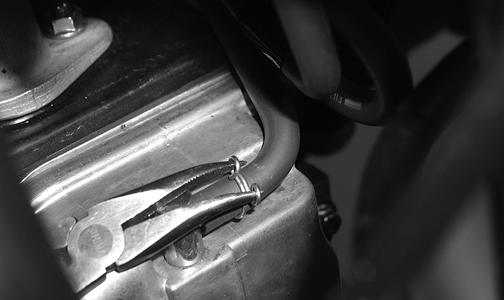
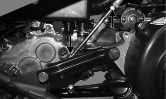
To check and adjust valve/tappet clearance, use the following procedure. NOTE: Valve/tappet clearance specifications are for room temperature (approximately 68° F). 1. Remove the two cap screws and the two self-tapping screws securing the fan shroud; then remove the fan shroud.
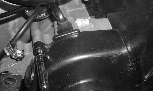
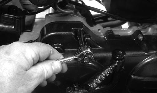
CD651 2. Remove the breather tube from the valve cover; then remove the four cap screws and remove the valve cover.
Account for the O-ring seal and the valve cover.
CD654
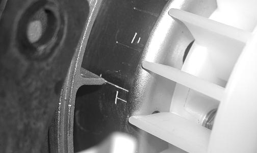
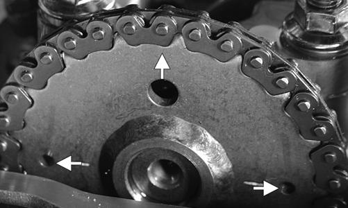
3. Remove the spark plug wire and the spark plug; then rotate the engine clockwise to the TDC position on the compression stroke. NOTE: The “T” mark on the rotor/flywheel is aligned with the timing pointer on the crankcase, and intake and exhaust valve adjuster screws must not have pressure on them. The two punch marks on the camshaft gear are aligned with the valve cover surface, and the hole in the timing gear points away from the engine.
CD652
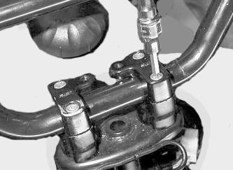
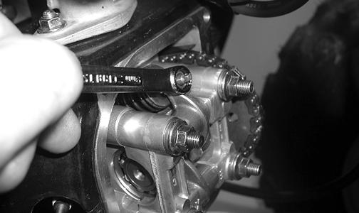
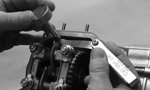
CD656A 4. Using a feeler gauge, check each valve tappet clearance. If the clearance is not 0.10 mm, loosen the jam nut and rotate the tappet adjuster screw until the clearance is within specifications. Tighten each jam nut securely after completing the adjustment.
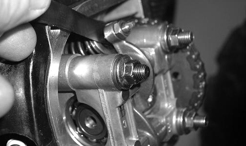
CD659 YT170 5. Check the valve/tappet clearance after the jam nut has been tightened to ensure the clearance did not change.
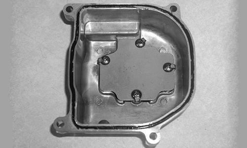
CD658 6. Install the valve cover and tighten the four cap screws to 7 ft-lb using a crisscross pattern; then install the breather tube. 7. Install the fan shroud and tighten the two cap screws securely. Tighten the self-tapping screws snug taking care not to strip the plastic cover. 8. Install the spark plug and tighten to 9 ft-lb; then install the spark plug wire.
Testing Engine Compression
To test engine compression, use the following procedure. 1. Remove the high tension lead from the spark plug. 2. Using compressed air, blow any debris from around the spark plug. ! WARNING
Always wear safety glasses when using compressed air.
3. Remove the spark plug; then attach the high tension lead to the plug and ground the plug on the cylinder head well away from the spark plug hole. 4. Attach the Compression Tester Kit (p/n 0444-213). NOTE: The engine must be warm and the battery must be fully charged for this test.
5. While holding the throttle lever in the full-open position, crank the engine over with the electric starter until the gauge shows a peak reading (five to 10 compression strokes). NOTE: Compression should be within a range of 195-230 psi in the full-open throttle position. 6. If compression is abnormally low, inspect the following items.
A.Verify starter cranks engine over.
B.Gauge is functioning properly.
C.Throttle lever in the full-open position. 7. Pour 29.5 ml (1 fl oz) of oil into the spark plug hole, reattach the gauge, and retest compression. 8. If compression is now evident, service the piston rings (see Steering/Frame/Controls section - Servicing Top-Side Components).
Spark Plug
A light brown insulator indicates the plug is correct. A white or dark insulator indicates that the engine may need to be serviced or the carburetor may need to be adjusted. To maintain a hot, strong spark, keep the plug free of carbon.
CAUTION
Before removing the spark plug, be sure to clean the area around the spark plug. Dirt could enter engine when removing or installing the spark plug.
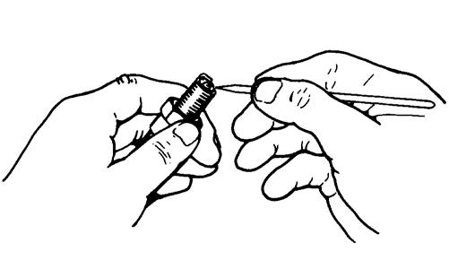
ATV-0051 Adjust the gap to 0.6-0.7 mm (0.024-0.028 in.) for proper ignition. Use a feeler gauge to check the gap. When installing the spark plug, be sure to tighten it to specifications. A new spark plug should be tightened 1/2 turn once the washer contacts the cylinder head. A used spark plug should be tightened 1/8 - 1/4 turn once the washer contacts the cylinder head.
Muffler/Spark Arrester
To clean the arrester, use the following procedure.
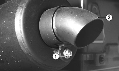
1. Remove the cap screw (1) securing the spark arrester assembly (2) to the rear of the muffler. Account for a gasket. ! WARNING
Before removing the muffler/spark arrester, wait for it to cool to avoid burns.
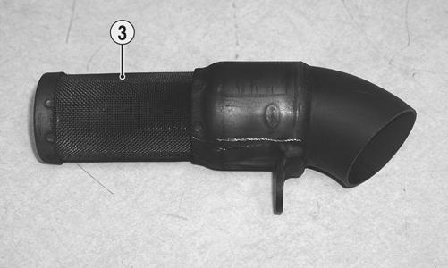
KM139A 2. Clean the screen (3) with a brush and parts-cleaning solvent. Dry with compressed air. If the screen has any holes or tears, it must be replaced.
KM140B
! WARNING
Before installing the spark arrester, wait for the muffler to cool to avoid burns.
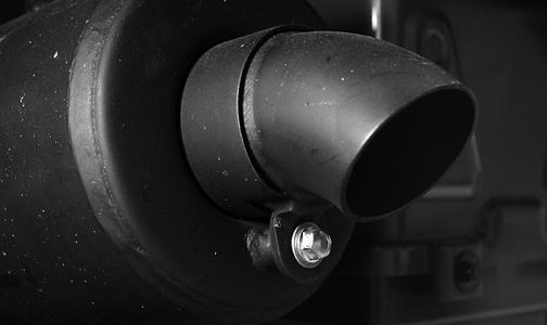
3. Install the spark arrester in the muffler and secure with the cap screw. Tighten securely.
KM139
Transmission Lubricant
1. Park the ATV on level ground. 2. Remove the level plug from the lower-right side of the transmission; then remove the fill plug from the upper-right side of the transmission. Be careful not to allow contaminates to enter the opening.
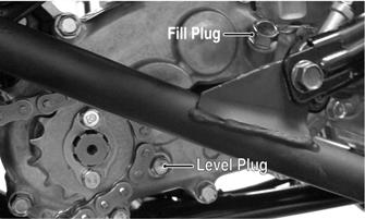
YT188A 3. Remove the drain plug from the bottom of the transmission and drain the lubricant into a drain pan.
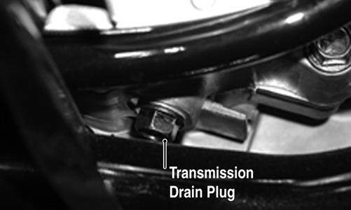
KM038A 4. Install the drain plug and tighten to 18 ft-lb. Pour the recommended lubricant in the fill hole while observing the oil level hole. Stop pouring if oil is observed at the threads of the oil level hole. Install and tighten the oil level plug. 5. Start the engine (while the ATV is outside on level ground) and drive it a short distance. 6. Turn the engine off and wait approximately one minute. Remove the level and recheck the lubricant level. The level should be visible at the level hole. If lubricant is not visible, add recommended lubricant until the level is visible at the level hole. 7. Inspect the area around the drain plug for leaks.
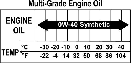
Engine Oil
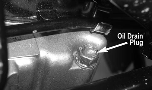
1. Move the ATV outdoors and start and warm up the engine. Shut the engine off; then place a drain pan under the engine oil drain plug located on the leftside rear of the engine under the kick starter.
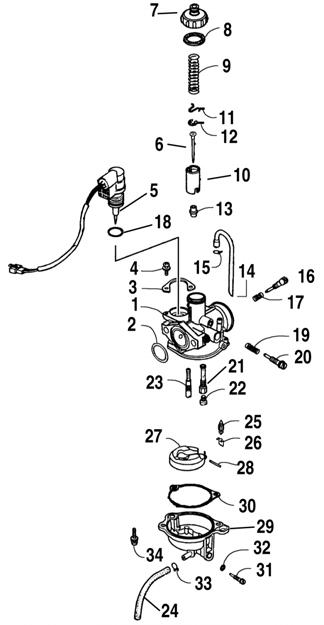
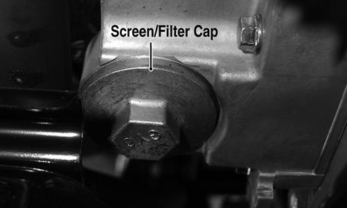
CD634A 2. Remove the oil drain plug and drain the engine oil into the pan; then install the oil drain plug and tighten to 18 ft-lb. 3. Move the drain pan to the right-front of the engine and remove the oil screen/filter cap. Account for a screen, spring, and O-ring.
KM040A
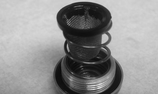
4. Clean the oil screen in parts-cleaning solvent using a brush; then install the screen, spring, and cap making sure the O-ring is seated properly in the cap. Tighten to 10 ft-lb.
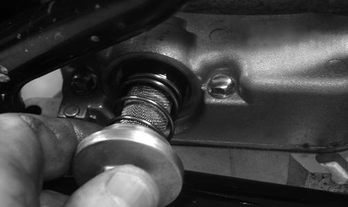
CD626 5. Remove the oil level stick and pour the recommended amount and viscosity oil into the engine; then install the oil level stick.
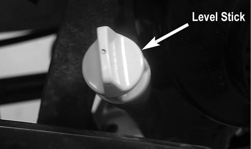
CD629B
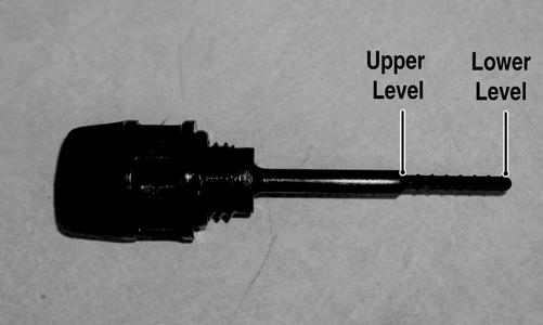
6. Start and warm up the engine. 7. Shut the engine off and allow to stand for 2-3 minutes. 8. Remove the oil level stick and wipe with a clean cloth. 9. Install the oil level completely into the engine. 10. Remove the oil level stick; the engine oil level should be at the appropriate level.
KM022A 11. Inspect the area around the drain plug and oil screen/ filter cap for leaks.
Brake Systems
! WARNING
After servicing brake-related components, ALWAYS check and adjust brakes as necessary before operating the ATV. Although the brake systems have been adjusted at the factory, the brakes should be checked for proper operation. The brakes must be maintained to be fully functional. CHECKING FRONT WHEEL BRAKE 1. With the engine off, compress the right-side (front) brake lever and attempt to move the ATV. If the front wheels are locked, it is adjusted properly. 2. If the front wheels are not locked or if only one wheel locks, adjustment is necessary. CHECKING REAR WHEEL BRAKE 1. With the engine off, compress the left-side (rear) brake lever and set the brake lever lock; then attempt to move the ATV. If the rear wheels are locked, it is serviceable. 2. If the rear wheels are not locked, bleed the brake system or replace the pads as necessary. ADJUSTING FRONT WHEEL BRAKE 1. Raise the ATV enough to allow the front wheels to spin freely. 2. Loosen both jam nuts on the right-side (front) brake lever. Turn both cable adjusters counterclockwise until both front wheels do not spin freely.
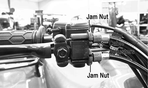
KC555B 3. Turn both cable adjusters in 1/4 turn increments (clockwise) until the wheels spin with a very slight amount of drag. 4. Lower the ATV; then push it forward and compress the brake lever. 5. If the front wheels lock evenly, adjustment is correct. 6. If the front wheels do not lock evenly, additional adjustment is necessary. 7. Once proper adjustment is obtained, tighten the jam nuts.
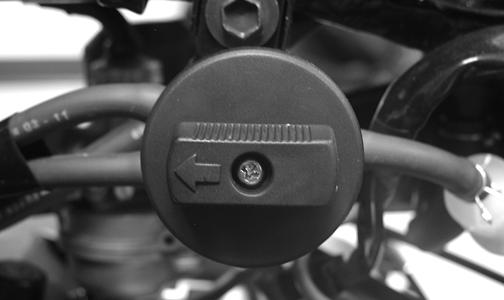
NOTE: The parking brake lever must be in the off position when adjusting the parking brake cable. 1. Loosen the jam nut (A); then finger tighten the adjuster bolt (B) until resistance is felt.
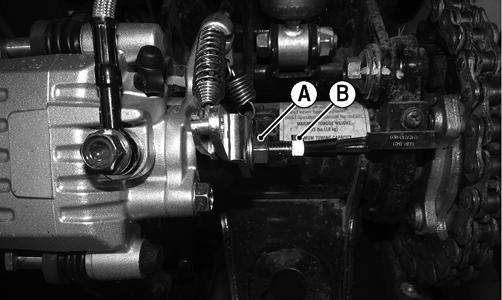
KC553A 1. Loosen the jam nut (A); then finger tighten the adjuster bolt (B) until resistance is felt. 2. Loosen the adjuster bolt (B) 1/8-1/4 turn. 3. While holding the adjuster bolt (B), tighten the jam nut (A) securely. NOTE: There should be no resistance on the brake disc from the brake pads after adjusting. MEASURING/REPLACING BRAKE SHOES/PADS Removing Front Brake Shoes 1. Support the ATV on a support stand. 2. Remove both front wheels and account for the cap screws. 3. Remove the cotter pins, castle nuts, and washers; then remove the brake drums/wheel hubs. 4. Loosen the brake shoe return spring; then remove the brake shoes.
MD2042
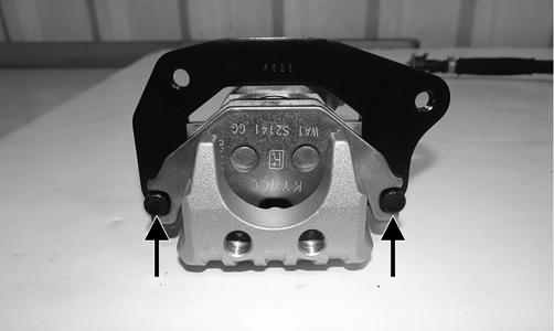
Removing Rear Brake Pads 1. Remove the two cap screws securing the brake pads to the caliper.

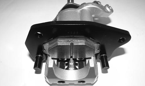
KC558A 2. Remove the two cap screws securing the brake caliper to the axle housing; then lift the caliper off the disc.
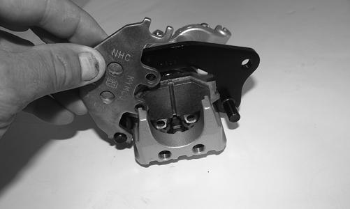
KC561A 3. Depress the holder pins and disengage the outer pad; then remove the inner pad.
KC566A
KC565
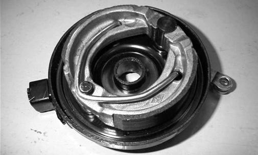
Inspecting and Measuring 1. Inspect the pads for gouges, chips, or wear. 2. Inspect the disc for gouges, grooves, cracks, and warpage. 3. Using a calipers, measure the thickness of each brake pad. 4. If the thickness of any brake pad is less than 1.0 mm (0.039 in.), the brake pads must be replaced. NOTE: The brake pads should be replaced as a set. Installing Front Brake Shoes 1. Place the brake shoes onto the backing plate over the stationary pivot pin and rotating cam. 2. Install the brake return spring.
MD2044 3. Install the wheel hub, washer, and castle nut. Tighten the castle nut to 45 ft-lb; then install a new cotter pin. 4. Install the wheel. Tighten to 30 ft-lb. 5. Repeat this procedure for the other side; then adjust the brake. 6. Remove the ATV from the support stand. Installing Rear Brake Pads 1. Install the inner brake pad; then install the outer pad onto the holder pins.
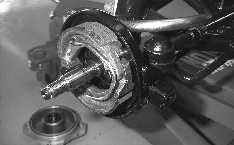
KC565 KC564 2. Spread the brake pads and place the caliper over the disc; then secure with two new cap screws.
KC561A 3. Install new “patch-lock” cap screws and tighten to 13 ft-lb.
KC558A
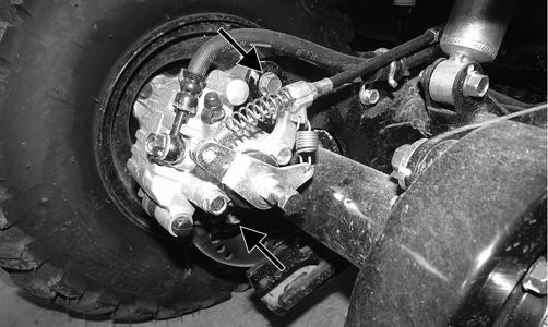
NOTE: Always compress the hydraulic brake lever several times to check that the brakes are firm. If the brakes are not firm, bleeding the system is necessary. BLEEDING To bleed the brake system, use the following procedure. 1. Remove the brake fluid reservoir cover and fill the reservoir with DOT 4 brake fluid. 2. Install and secure the cover. 3. Remove the protective cap from the bleed screw and connect one end of a clear hose to the bleed screw and direct the other end into a suitable container.
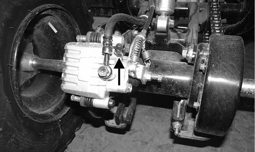
KC562A 4. Slowly compress the brake lever several times; then while holding slight pressure on the brake lever, open the bleed screw and watch for air bubbles in the hose.
Close the bleed screw before releasing the brake lever.
Repeat this procedure until no air bubbles are present. NOTE: During the bleeding procedure, watch the reservoir sight glass to make sure there is always a sufficient amount of brake fluid in the reservoir. Failure to maintain sufficient amount of fluid in the reservoir will result in air being in the system. 5. Repeat step 4 until the brake lever is firm.
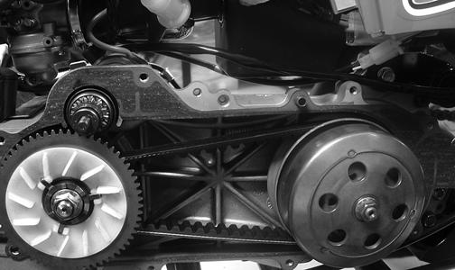
Replacing Drive Belt
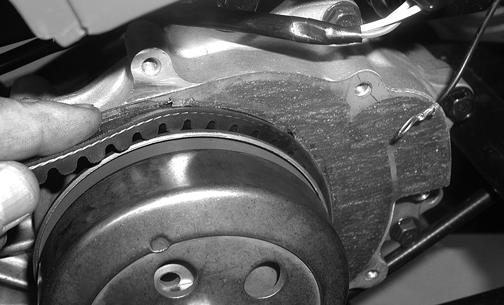
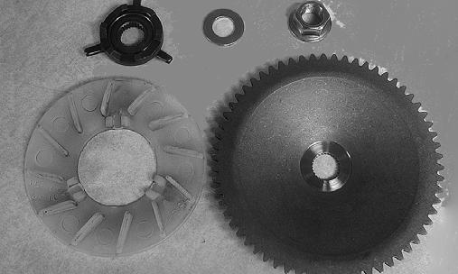
REMOVING 1. Remove the eight Phillips-head cap screws and four cap screws securing the footrest cover to the footrest and front and rear fenders; then remove footrest cover. 2. Remove the cooling duct. 3. Remove the eight cap screws securing the drive clutch cover; then remove the cover. Account for a gasket and two alignment pins. NOTE: The gasket does not need to be removed unless it is being replaced or unless additional servicing is being done requiring its removal. 4. Remove the nut securing the stationary drive sheave to the crankshaft; then remove the stationary drive sheave. Account for a washer, kick starter ratchet, and cooling fan. 5. Open the movable sheave on the driven clutch assembly with a suitable pry bar or wedge; then remove the drive belt.
CD624
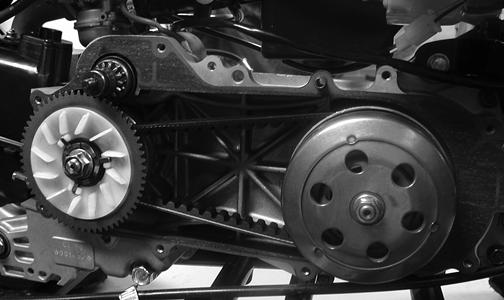
INSTALLING 1. If removed, place the gasket and two alignment pins into position on the crankcase. 2. Spread the faces of the driven clutch with a suitable pry bar or wedge; then when the faces are separated, insert the drive belt.
CD624
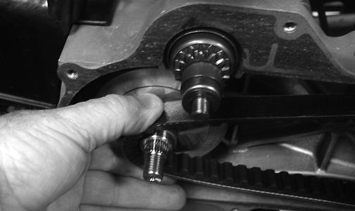
NOTE: If the drive belt has an arrow stamped on the outer face, it should point forward (direction of rotation). 3. Pinch the drive belt together near its center and slide the stationary drive sheave over the crankshaft.
Install the washer, kick starter ratchet, and cooling fan. Secure the stationary drive sheave with a nut (threads coated with red Loctite #271). Tighten the nut to 27.5 ft-lb.
CD623
CD619 4. Rotate the drive belt and sheaves until the drive belt is flush with the top of the driven clutch.
CD620 5. Place the V-belt cover and one rear brake cable tab into position; then secure with the eight cap screws.
CD617
6. Tighten the cover cap screws to 7 ft-lb. 7. Install the cooling duct. 8. Place the footrest cover into position and secure it to the footrest with the Phillips-head cap screws.
Tighten securely. 9. Secure the footrest cover to the front and rear fenders with the Phillips-head cap screws and four cap screws. Tighten securely.
Adjusting Shift Linkage
If the ATV jumps out of gear, is difficult to get in gear, or the neutral and reverse indicator lights do not illuminate, shift linkage adjustment may be necessary. 1. Shift the transmission into reverse; then remove the cap screw securing the linkage to the transmission shift arm. 2. Verify the transmission is in reverse, the ignition switch is in the ON position, the reverse indicator light is illuminated, and the shift lever is fully in the reverse position; then loosen the upper and lower jam-nuts on the shift linkage and adjust the linkage to align with the shift arm.
YT005B 3. Install the cap screw securing the linkage to the lower shift arm. Do not tighten at this time. 4. Shift the transmission into neutral and verify the neutral indicator illuminates; then tighten the jam-nuts and the linkage cap screw securely.