14 minute read
Fuel/Lubrication/Cooling

! WARNING
Whenever any maintenance or inspection is performed on the fuel system during which there may be fuel leakage, there should be no welding, smoking, open flames, etc., in the area.
TROUBLESHOOTING 1. Verify that the electric fuel pump is operating by listening for a “whirring” sound for several seconds after the ignition switch is turned to the ON position.
If no sound can be heard, see Electric Fuel
Pump/Fuel Level Sensor in this section. 2. Check for a flashing DTC on the LCD. If DTC is flashing, see EFI Diagnostic System in the Electrical
System section. 3. Make sure there is sufficient, clean gas in the gas tank. 4. Verify that the battery is sufficiently charged to crank the engine over at normal speed. 5. Check the air filter housing and air filter for contamination. Clean or replace as necessary (see Periodic
Maintenance section). NOTE: Arctic Cat recommends the use of new gaskets, lock nuts, and seals and lubricating all internal components when servicing the engine/transmission.
SPECIAL TOOLS A number of special tools must be available to the technician when performing service procedures in this section. Refer to the current Special Tools Catalog for the appropriate tool description.
Description
Oil Pressure Test Kit Tachometer p/n
0644-495 0644-275
NOTE: Special tools are available from the Arctic Cat Service Department.
Throttle Body
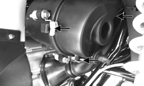
REMOVING 1. Remove the heat shields and seat. 2. Disconnect the negative battery cable; then remove the gas tank (see Gas Tank in this section). 3. Loosen the clamp securing the intake boot to the throttle body; then loosen the clamp securing the intake boot to the intake housing and slide the intake housing rearward.
! WARNING
Gasoline may be under pressure. Place an absorbent towel under the connector to absorb any gasoline spray when disconnecting.
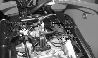
FI691A 4. Disconnect the MAP/IAT sensor connector, ISC connector, and TPS connector; then loosen the clamp securing the throttle body to the intake manifold boot and slide the throttle body out.
FI528A 5. Remove the throttle arm cover and loosen the throttle cable jam nut; then disconnect the throttle cable and remove the throttle body. INSTALLING 1. Connect the throttle cable to the throttle arm; then install the throttle cable housing in the throttle body and tighten the jam nut. Install the throttle arm cover and secure with two machine screws. 2. Place the throttle body into the intake manifold boot and tighten the boot clamp securely. 3. Place the intake housing into the boots and tighten the boot clamps securely. 4. Install the gas tank; then the heat shields and seat.
Throttle Cable Free-Play
To adjust throttle cable free-play, see Periodic Maintenance.
Gas Tank
! WARNING
Whenever any maintenance or inspection is made on the fuel system during which there may be fuel leakage, there should be no welding, smoking, open flames, etc., in the area.
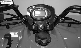
REMOVING 1. Disconnect the negative battery cable; then remove the seat and side panels. 2. Remove the cap screws securing the instrument pod and move it forward.
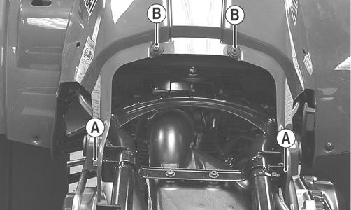
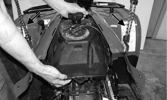
KC507A 3. Remove the cap screws (A) securing the rear of the front body to frame; then remove two reinstallable rivets (B) securing the gas tank cover to the body.
KC219A 4. Remove the gas tank cap; then remove the gas tank cover. Place the gas tank cap back on the tank.
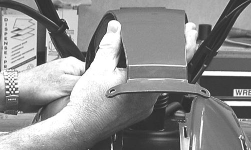
KC220 5. Using suitable straps, hook the plastic at rear of gas tank and route it over the handlebar to the front rack; then pull it tight to spread open the plastic at the rear of the gas tank. This will aid in removing and installing gas tank.
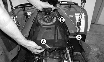
KC509A 6. Remove the cap screw (A) securing the gas tank to the frame; then disconnect the gasline hose (B) and fuel pump (C). Remove the gas tank to the rear.
Account for the heat shield.
! WARNING
Do not turn the ignition switch to the ON position with the hoses removed. Gasoline will be pumped by the electric fuel pump causing a safety hazard. ! WARNING
Gasoline may be under pressure. Place an absorbent towel under the connector to absorb any gasoline spray when disconnecting.
KC509B
CLEANING AND INSPECTING 1. Clean all gas tank components with parts-cleaning solvent. 2. Inspect all hoses for cracks or leaks. 3. Inspect tank cap and tank for leaks, holes, and damaged threads. INSTALLING 1. Using straps to hold the front plastic open, place the gas tank into position in the frame making sure the heat shield is in position. 2. Connect the fuel pump and gasline hose; then secure the gas tank with the cap screw and tighten securely.
KC509B 3. Using existing the cap screws, secure the instrument pod into position and tighten the screws securely. 4. Remove the straps. 5. Secure the rear of the front plastic to the frame with the cap screws (A) and tighten securely; then install the gas tank cover and secure it with reinstallable rivets (B).
KC219A 6. Connect the negative battery cable; then install the side panels and seat making sure they all lock securely in place.
Oil Filter/Oil Pump
NOTE: Whenever internal engine components wear excessively or break and whenever oil is contaminated, the oil pump should be replaced. The oil pump is not a serviceable component.
Testing Oil Pump Pressure
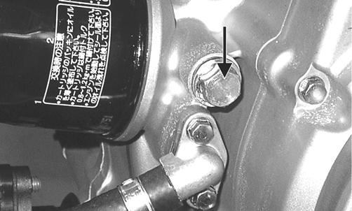
1. Connect the Tachometer to the engine or place the gauge in diagnostic mode and select “tACH.” 2. Connect the Oil Pressure Test Kit to the oil filter drain plug.
KC195A
NOTE: Some oil seepage may occur when installing the oil pressure gauge. Wipe up oil residue with a cloth.
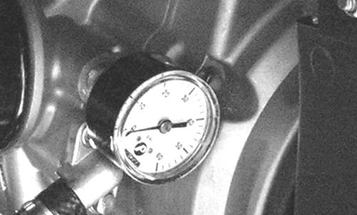
KC267 3. Warm up the engine to normal operating temperature (cooling fan cycling); then increase engine RPM to 3000 RPM. The oil pressure must read 0.6-0.7 kg/cm2 (8.5-10 psi). NOTE: If the oil pressure is lower than specified, check for low oil level, defective oil pump, or restricted oil cooler.
NOTE: If the oil pressure is higher than specified, check for clogged oil passage, clogged oil filter, or improper installation of the oil filter.
Liquid Cooling System
When filling the cooling system, use premixed Arctic Cat Antifreeze. While the cooling system is being filled, air pockets may develop; therefore, run the engine for five minutes after the initial fill, shut the engine off, and then fill the cooling system to the bottom of the stand pipe in the radiator neck.
RADIATOR Removing 1. Drain the coolant at the engine. 2. Remove the front rack and body panel (see Steering/Frame/Controls section). 3. Remove the upper and lower coolant hoses; then remove the fill hose and air bleed hose. 4. Remove the cap screws securing the radiator to the frame. 5. Disconnect the fan wiring from the main wiring harness; then remove the radiator/fan assembly and account for the grommets and collars. 6. Remove the fan/fan shroud assembly from the radiator. Cleaning and Inspecting 1. Flush the radiator with water to remove any contaminants. 2. Inspect the radiator for leaks and damage. 3. Inspect all hoses for cracks and deterioration. 4. Inspect all fasteners and grommets for damage or wear. Installing 1. Position the fan/fan shroud assembly on the radiator; then secure with existing hardware. 2. Place the radiator with grommets and collars into position on the frame; then install the cap screws.
Tighten securely. 3. Install the upper and lower coolant hoses, fill hose, and air bleed hose; then secure with hose clamps.
CAUTION
After operating the ATV for the initial 5-10 minutes, stop the engine, allow the engine to cool down, and check the coolant level. Add coolant as necessary.
AF734D 4. Install the front body panel and rack (see Steering/Frame/Controls section). 5. Fill the cooling system with the recommended amount of antifreeze. Check for leakage. 6. Connect the fan wiring to the main wiring harness. THERMOSTAT Removing 1. Drain approximately one quart of coolant from the cooling system. 2. Remove the two cap screws securing the thermostat housing to the mounting bracket. Remove the thermostat housing cover and account for an O-ring and a thermostat. Inspecting 1. Inspect the thermostat for corrosion or spring damage. 2. Using the following procedure, inspect the thermostat for proper operation.
A.Suspend the thermostat in a container filled with water.
B.Heat the water and monitor the temperature with a thermometer.
C.The thermostat should start to open at 71-86° C (160-187° F).
D.If the thermostat does not open, it must be replaced. 3. Inspect all coolant hoses, connections, and clamps for deterioration, cracks, and wear. NOTE: All coolant hoses and clamps should be replaced every four years or 4000 miles.
Installing 1. Place the thermostat and O-ring into the thermostat housing; then secure the thermostat housing to the mounting bracket with the two cap screws. 2. Fill the cooling system to the recommended level with antifreeze. Check for leakage. WATER PUMP NOTE: The water pump is a non-serviceable component. It must be replaced as an assembly.
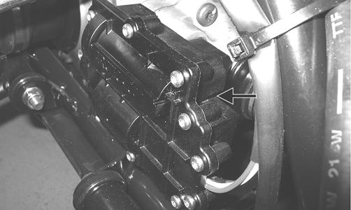
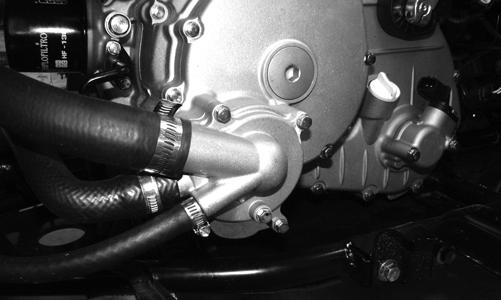
Removing 1. Remove the radiator cap; then remove the water pump drain and drain the coolant.
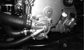
FI530A
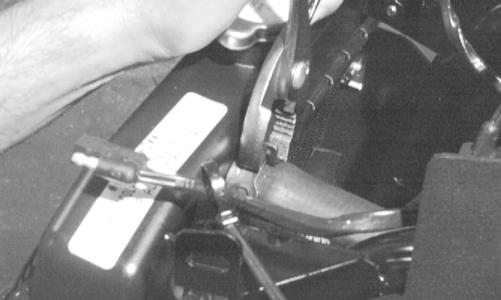
2. Drain the oil from the engine/transmission. 3. Remove the four torx-head cap screws securing the front and rear fenders to the footrest; then remove the four cap screws securing the footrest to the frame.
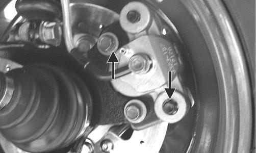
Remove the footrest. 4. Loosen the hose clamps and slide the clamps away from the hose ends approximately 2 in.; then remove the hoses from the water pump. 5. Remove the four cap screws securing the water pump to the engine; then remove the water pump.
FI538A
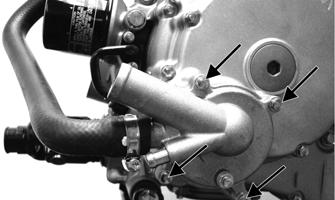
Installing 1. Secure the water pump to the engine with the four cap screws tightened to 8 ft-lb.
FI538A FI530 3. Place the footrest into position on the frame and loosely secure with four cap screws; then secure the front and rear fenders to the footrest with the four torx-head cap screws. Tighten the four torx-head cap screws securely; then tighten the remaining cap screws to 20 ft-lb. 4. Fill the engine/transmission with the proper amount of recommended oil. 5. Fill the cooling system with the proper amount of recommended coolant.
Electric Fuel Pump/Fuel Level Sensor
NOTE: Preliminary checks may be performed on this component using the diagnostic mode on the LCD gauge (see EFI Diagnostic System in the Electrical System section).
The electric fuel pump and fuel level sensor are not serviceable components. If either component fails, it must be replaced. TESTING
1. Turn the ignition switch ON and listen for a momentary “whirring” sound of the pump building pressure.
If the sound is heard (10 seconds), no electrical checks are necessary. Turn the ignition switch OFF.
! WARNING
Whenever any maintenance or inspection is made on the fuel system during which there may be fuel leakage, there should be no welding, smoking, open flames, etc., in the area.
AT THIS POINT
Prior to removing the electric fuel pump, the following check should be performed to determine that removal is necessary.
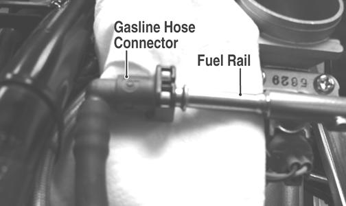
2. Disconnect the gasline hose from the throttle body; then install a suitable pressure gauge. ! WARNING
Gasoline may be under pressure. Place an absorbent towel under the connector to absorb any gasoline spray when disconnecting.
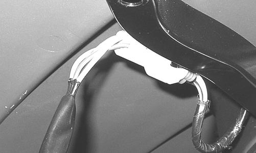
FI092A 3. Turn the ignition switch to the ON position. The fuel pressure should build until the pump shuts off. Pressure should read 3.0 kg-cm2 (43 psi). 4. If the pump is not running, disconnect the fuel pump/tank sensor connector by reaching under the rear rack from behind. 5. Connect a multimeter to the power supply leads with the red tester lead to the red wire and the black tester lead to the black wire; then turn the ignition switch to the ON position. The meter should read battery voltage. If battery voltage is indicated and the fuel pump does not run, replace the pump assembly. If no battery voltage is indicated, check the ECM and the vehicle tilt sensor. REMOVING 1. Disconnect the negative battery cable from the battery. 2. Remove the seat and side heat shields; then remove the cap screws (A) securing the rear of the front body to the frame; then remove two reinstallable rivets (B) securing the gas tank cover to the body.
KC219A 3. Remove the gas cap; then remove the tank cover and install the gas cap back on the tank.
KC220 4. Mark the fuel pump and gas tank for proper orientation during assembly; then disconnect the fuel pump/fuel level sender connector.
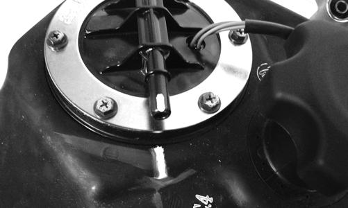
KC423 5. Disconnect the gas line connector from the fuel pump outlet.
6. Remove the screws securing the fuel pump to the gas tank; then make a reference mark on the fuel pump and tank. 7. Lift out the fuel pump assembly and carefully guide the pump and float lever through the opening in the gas tank.
8. Using duct tape or other suitable means, cover the fuel pump opening.
! WARNING
Gasoline may be under pressure. Place an absorbent towel under the connector to absorb any gasoline spray when disconnecting. ! WARNING
Do not turn the ignition switch to the ON position with the hoses removed. Gasoline will be pumped by the electric fuel pump causing a safety hazard.
CAUTION
Take care not to damage the float or float arm or replacement of the entire assembly will be necessary.
If the pump has failed earlier test and must be replaced, proceed to INSTALLING. 1. Inspect the fuel screen and blow clean with low pressure compressed air. 2. Move the float lever and check for free movement.
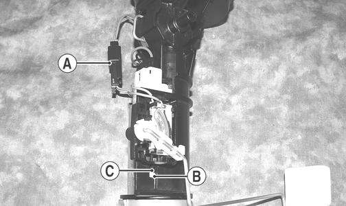
The float assembly should return to the lower position without force. If not, replace the fuel pump assembly. 3. Test the fuel level sensor by connecting a multimeter (A) to the fuel level sensor leads (B); then select
OHMS. The multimeter should show 86 ohms at full fuel position (C) and 5 ohms at empty fuel position (D).
ATV2116
NOTE: If readings are erratic, clean the resistor wiper and resistor with clean alcohol and retest. If still not correct, replace the fuel level sensor.
4. To replace the fuel level sensor, use the following procedure.
A.Disconnect the two-wire connector (A); then press the fuel level sensor toward the top of the fuel pump to release it from the mounting slot (B).
FI460A
B.Engage the tabs (C) of the fuel level sensor into the mounting slot (B) and press toward the bottom of the fuel pump to latch in place; then connect the two-wire connector (A). INSTALLING 1. Mark the new fuel pump with a reference mark in the same location as the removed pump; then place the new gasket on the pump. 2. Remove the material covering the fuel pump opening; then carefully guide the fuel pump into position taking care not to damage the float or float lever.
KX190 3. Rotate the fuel pump until the match marks align; then install the mounting screws and tighten securely using a crisscross pattern. NOTE: It is important to install the fuel pump with the correct orientation to ensure adequate float lever clearance.
4. Connect the wires and fuel hose; then connect the negative battery cable and turn the ignition switch to the ON position. Note that the fuel pump runs momentarily and the fuel gauge indicates the proper fuel level. 5. With the transmission in neutral and brake lever lock engaged, start the engine and check for normal operation. Check for any fuel leaks. 6. Install the gas tank cover, side heat shields, and seat making sure the seat locks securely.
Troubleshooting
Problem: Starting impaired Condition Remedy 1. Gas contaminated 1.Drain gas tank and fill with clean gas Problem: Idling or low speed impaired Condition Remedy 1. TPS out of adjustment 1.Adjust TPS Problem: Medium or high speed impaired Condition Remedy 1. High RPM “cut out” against RPM limiter 1.Decrease RPM speed