21 minute read
Periodic Maintenance/Tune-Up

SPECIAL TOOLS A number of special tools must be available to the technician when performing service procedures in this section. Refer to the current Special Tools Catalog for the appropriate tool description.
Description
Compression Tester Kit Tappet Adjuster p/n
0444-213
0444-189
NOTE: Special tools are available from the Arctic Cat Service Parts Department.
Lubrication Points
It is advisable to lubricate certain components periodically to ensure free movement. Apply light oil to the components using the following list as reference.
A.Throttle Lever Pivot/Cable Ends
B.Brake Lever Pivot
C.Auxiliary Brake Pivot/Clevis
D.Choke Cable Upper End
E.Shift Lever/Ball Joints
F. Idle RPM Screw
Air Filter
Use the following procedure to remove the filter and inspect and/or clean it. CLEANING AND INSPECTING FILTER
CAUTION
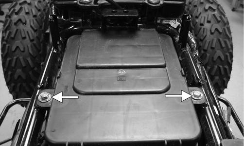
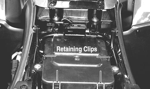
Failure to inspect the air filter frequently if the vehicle is used in dusty, wet, or muddy conditions can damage the engine. 1. Remove the seat. 2. Remove the air filter housing cover from the retaining clips.
KM095A
3. Loosen the clamp; then remove the filter.
KM097B 4. Fill a wash pan larger than the filter with a non-flammable cleaning solvent; then dip the filter in the solvent and wash it.
NOTE: Foam Filter Cleaner and Foam Filter Oil are available from Arctic Cat.
5. Dry the filter. 6. Put the filter in a plastic bag; then pour in air filter oil and work the filter.
7. Clean any dirt or debris from inside the air cleaner.
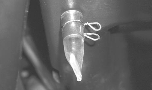
Make sure no dirt enters the carburetor. 8. Place the filter in the air filter housing making sure it is properly seated and secure with the clamp. 9. Install the air filter housing cover and secure with the retaining clips; then install the seat making sure it locks securely. CHECKING/DRAINING DRAIN TUBE Periodically check the drain tube for gasoline or oil accumulation. If noticed, remove the drain tube cap from beneath the housing and drain the gasoline or oil into a suitable container; then install and secure the tube cap.
CAUTION
A torn air filter can cause damage to the ATV engine. Dirt and dust may get inside the engine if the element is torn. Carefully examine the element for tears before and after cleaning it. Replace the element with a new one if it is torn.
KM114
Valve/Tappet Clearance
To check and adjust valve/tappet clearance, use the following procedure. NOTE: The seat assembly, side panels, and gas tank must be removed for this procedure. 1. Remove the timing inspection plug; then remove the cylinder head cover (see Engine/Transmission -
Removing Top-Side Components). 2. Rotate the crankshaft so the “T” mark on the flywheel aligns with the index mark on the right-side crankcase cover.
NOTE: At this point, the round hole in the camshaft gear should be up. 3. Place Tappet Adjuster onto the jam nut securing the tappet adjuster screw; then rotate the adjuster dial clockwise until the end is seated in the tappet adjuster screw. 4. While holding the adjuster dial in place, use the adjuster handle and loosen the jam nut; then rotate the tappet adjuster screw clockwise until friction is felt. 5. Align the adjuster handle with one of the marks on the adjuster dial. 6. While holding the adjuster handle in place, rotate the adjuster dial counterclockwise until proper valve/ tappet clearance is attained. NOTE: Refer to the appropriate specifications in Engine/ Transmission for the proper valve/tappet clearance. NOTE: Rotating the adjuster dial counterclockwise will open the valve/tappet clearance by 0.05 mm (0.002 in.) per mark. 7. While holding the adjuster dial at the proper clearance setting, tighten the jam nut securely with the valve adjuster handle. 8. Place the cylinder head cover with a new O-ring into position; then tighten the cover securely.
KM703
9. Install the timing inspection plug.
Testing Engine Compression
To test engine compression, use the following procedure. 1. Remove the high tension lead from the spark plug. 2. Using compressed air, blow any debris from around the spark plug. ! WARNING
Always wear safety glasses when using compressed air. 3. Remove the spark plug; then attach the high tension lead to the plug and ground the plug on the cylinder head well away from the spark plug hole. 4. Attach the gauge from Compression Tester Kit. NOTE: The engine must be warm and the battery must be fully charged for this test. 5. While holding the throttle lever in the full-open position, crank the engine over with the electric starter until the gauge shows a peak reading (five to 10 compression strokes). NOTE: The compression should be within a range of 210-230 psi in the full-open throttle position. 6. If compression is abnormally low, verify the following items.
A.Starter cranks engine over.
B.Gauge functions properly.
C.Throttle lever in the full-open position.
D.Valve/tappet clearance correct.
E.Valve not bent or discolored.
F. Valve seat not discolored. NOTE: To service valves, see Engine/Transmission Servicing Top Side Components. 7. Pour 29.5 ml (1 fl oz) of oil into the spark plug hole, attach the gauge, and test compression.
8. If compression is now evident, service the piston rings (see Engine/Transmission - Servicing Top Side
Components).
Spark Plug
A light brown insulator indicates that the plug is correct. A white or dark insulator indicates that the engine may need to be serviced or the carburetor may need to be adjusted. To maintain a hot, strong spark, keep the plug free of carbon.
ATV-0051
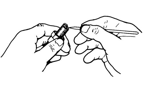
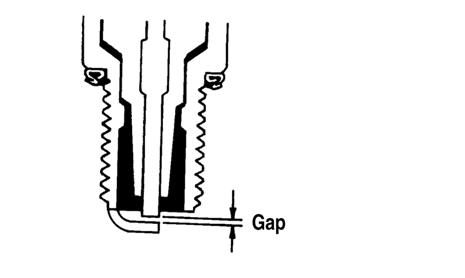
CAUTION
Before removing the spark plug, make sure to clean the area around the spark plug. Dirt could enter engine when removing or installing the spark plug. Adjust the gap to 0.8-0.9 mm (0.032-0.036 in.) for proper ignition. Use a wire feeler gauge to check the gap.
ATV0052B When installing the spark plug, make sure to tighten it securely. A new spark plug should be tightened 1/2 turn once the washer contacts the cylinder head. A used spark plug should be tightened 1/8-1/4 turn once the washer contacts the cylinder head.
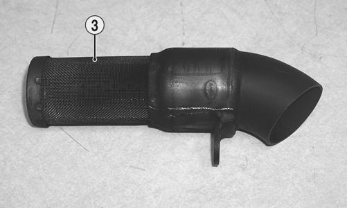
Muffler/SparkArrester
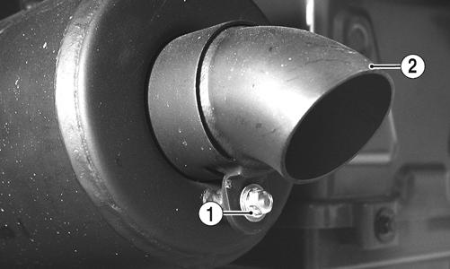
The muffler has a spark arrester which must be periodically cleaned. At the intervals shown in the Periodic Maintenance Chart, clean the spark arrester using the following procedure.
1. Remove the cap screw (1) securing the spark arrester (2) to the muffler assembly; then carefully remove the spark arrester.
! WARNING
Wait until the muffler cools to avoid burns.
KM139A 2. Using a soft wire brush, clean the carbon from the screen (3) taking care not to tear or damage the screen.
KM140B 3. Install the spark arrester and secure with the cap screw. Tighten securely.
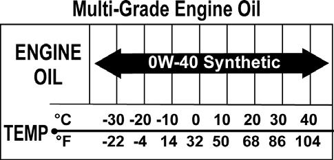
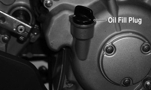
Engine Oil - Filter
Replace the engine oil and clean the screen/filter at the scheduled intervals. The engine should always be warm when the oil is changed so the oil will drain easily and completely. 1. Park the ATV on level ground. 2. Loosen the oil fill plug.
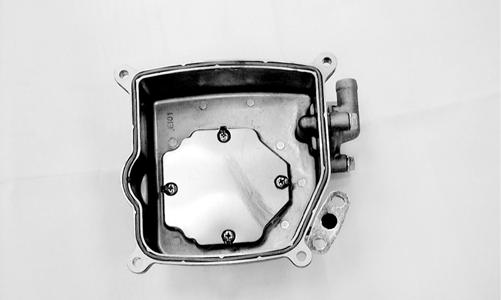
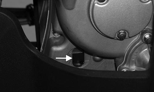
KM126A 3. Remove the screen/filter cap from the bottom of the engine and drain the oil into a drain pan. Account for a spring, O-ring, and screen/filter.
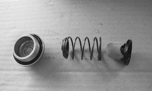
DSC02248 4. Clean the screen/filter in parts-cleaning solvent; then inspect the O-ring and replace if damaged. 5. Install the screen/filter, spring, and screen/filter cap into the bottom of the engine and tighten to 11 ft-lb. 6. Remove the oil fill plug and pour in 1.6 L (1.7 U.S. qt) of the recommended oil into the fill hole; then install the oil fill plug.
CAUTION
Any oil used in place of the recommended oil could cause serious engine damage. Do not use oils which contain graphite or molybdenum additives. These oils can adversely affect clutch operation. Also, not recommended are racing, vegetable, non-detergent, and castor-based oils.
7. Start the engine (while the ATV is outside on level ground) and allow it to idle for a few minutes. 8. Turn the engine off and wait approximately one minute.
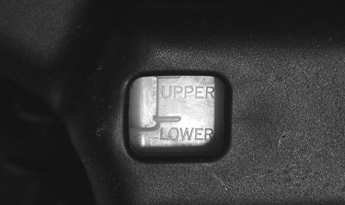
Check the oil level in the engine oil inspection window.
The oil level should be visible through the window. If oil is not visible, add recommended oil until the oil level is visible between the lines of the window.
KM127A 9. Inspect the area around the screen/filter cap for leaks.
Rear Drive Lubricant (Utility)
Check and change the lubricant according to the Periodic Maintenance Chart. When changing the lubricant, use approved SAE 80W-90 hypoid gear lube. To check lubricant, use the following procedure. 1. Remove the rear drive level plug; the lubricant level should be at the threads of the plug.
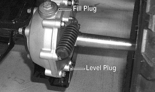
KM131A 2. If low, add SAE approved 80W-90 hypoid gear lube as necessary. To change the lubricant, use the following procedure. 1. Place the ATV on level ground. 2. Loosen the fill plug. 3. Remove the cap screws securing the rear drive gear guard; then remove the guard. 4. Drain the lubricant into a drain pan by removing the drain plug from the bottom of the rear drive. NOTE: If the rear drive lubricant is contaminated with water, inspect the drain plug, fill plug, and/or bladder.
5. After all the lubricant has been drained, install the drain plug and tighten securely. Install the rear drive gear guard and tighten the cap screws securely.
6. Pour the appropriate amount of recommended lubricant into the fill hole. Remove the level plug and check for appropriate level. 7. Install the fill plug.
CAUTION
Water entering the outer end of the axle will not be able to enter the rear drive unless the seals are damaged.
Transmission Lubricant
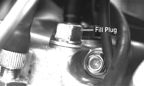
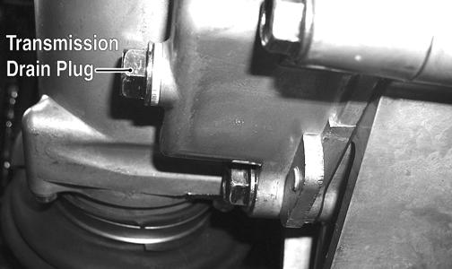
Change the lubricant according to the Periodic Maintenance Chart. When changing the lubricant, use approved SAE 80W-90 hypoid gear lube. To change the lubricant, use the following procedure. 1. Place the ATV on level ground. 2. Loosen the fill plug; then remove the transmission drain plug and drain the transmission lubricant.
KM104A
KM106A
3. Install the drain plug and tighten securely. 4. Remove the fill plug and pour the appropriate amount of recommended lubricant into the fill hole. 5. Install the fill plug and tighten securely. 6. Check the area around the drain plug for leakage.
Drive Chain (DVX)
Drive chain condition and adjustment should be inspected each day before the ATV is operated. Always follow the following guidelines for inspecting and servicing the drive chain. ! WARNING
Failure to inspect and maintain the drive chain can be hazardous. Operating the ATV with the drive chain in poor condition or improperly adjusted can cause an accident resulting in possible injury. INSPECTING Inspect the drive chain for any of the following conditions.
A.Loose pins.
B.Loose or cracked rollers.
C.Dry or rusted links.
D.Kinked or binding links.
E.Excessive wear. The presence of any of the conditions requires drive chain replacement. NOTE: If the drive chain is worn or damaged, the sprockets may also be worn or damaged. Inspect the sprockets for worn, broken, or damaged teeth. Always inspect the sprockets when a new drive chain is being installed. CLEANING AND LUBRICATING The drive chain should be cleaned and lubricated frequently to prolong chain and sprocket life. Use the following procedure to clean and lubricate the chain. NOTE: This ATV is equipped with an O-ring type roller chain. Each link incorporates small O-rings to seal out water and dirt. Care should be taken to choose cleaning solutions and lubricants that are suitable for O-ring type chains. 1. Using a suitable, nonflammable cleaning solution, thoroughly wash the chain and sprockets. 2. Allow the chain to dry; then apply a dry, graphitebased lubricant to the chain.
NOTE: The drive chain should be lubricated with a dry, graphite-based chain lubricant. By using a dry, graphite-based chain lubricant, dirt build-up on the drive chain will be minimized.
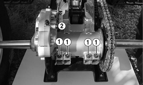
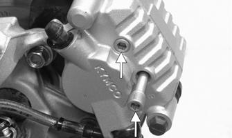
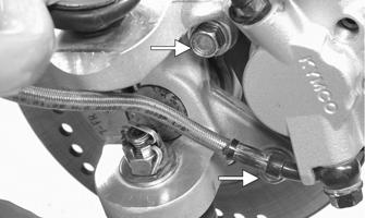
ADJUSTING TENSION 1. Loosen the four cap screws (1) at the rear of the axle housing; then loosen the cap screw (2) on the front of the brake caliper.
KM902A 2. Install an appropriate pin through the axle hub and rear sprocket.
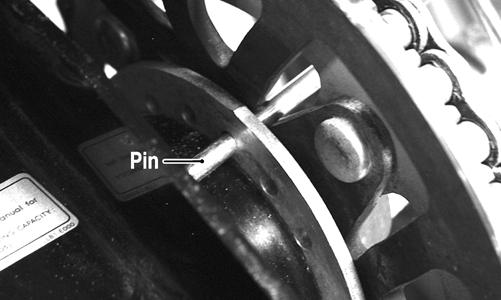
KM158A 3. With a person seated on the ATV, check chain tension at the mid-point of the chain. NOTE: Chain “slack” should be within a range of 30-40 mm (1.2-1.6 in.). 4. Push the ATV forward to tighten chain tension; push the ATV backward to loosen chain tension. 5. Tighten the four cap screws (1) to 29 ft-lb; then tighten the cap screw (2) to 29 ft-lb.
KM902A
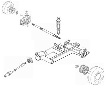
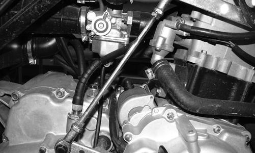
Driveshaft/Coupling (Utility)
The following drive system components should be inspected periodically to ensure proper operation.
Nuts/Bolts/Cap Screws
Tighten all nuts, bolts, and cap screws. Make sure rivets holding components together are tight. Replace all loose rivets. Care must be taken that all calibrated nuts, bolts, and cap screws are tightened to specifications (See General Information).
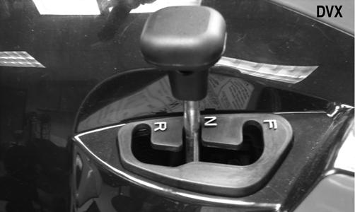
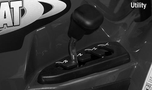
Shift Lever
KM363A
KM124B
CHECKING ADJUSTMENT Stop the ATV completely and shift the transmission into the R position. The reverse gear indicator light should be illuminated.
If the reverse gear indicator light does not illuminate when shifted to the reverse position, the switch may be faulty, the fuse may be blown, the bulb may be faulty, a connection may be loose or corroded, or the lever may need adjusting. To adjust, proceed to Adjusting Shift Lever. ! WARNING
Never shift the ATV into reverse gear when the ATV is moving as it could cause the ATV to stop suddenly throwing the operator from the ATV.
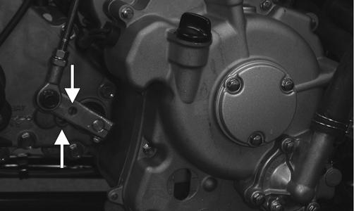
ADJUSTING SHIFT LEVER 1. Place the shift lever in the N (neutral) position; then set the engine stop switch to the STOP position and turn the ignition switch to the RUN position. The neutral indicator light should illuminate. NOTE: If the neutral indicator light does not illuminate, adjustment of the shift linkage will be required. To adjust, proceed to step 2. 2. Loosen the jam nuts on both ends of the shift rod and turn the shift rod until the neutral light illuminates.
Tighten the jam nuts securely.
KM313
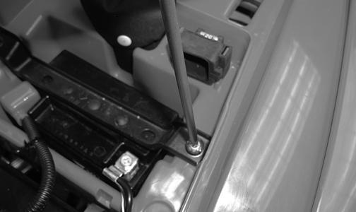
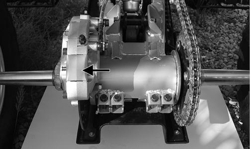
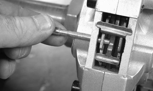
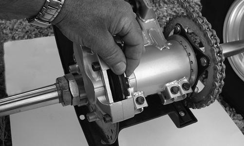
NOTE: On the DVX, the neutral position in the transmission is indexed by passing a Phillips screwdriver through the transmission shift arm and into the index hole in the transmission cover.
KM179A
Hydraulic Brake Systems
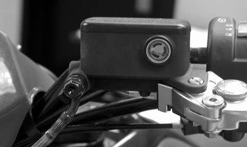
CHECKING/BLEEDING The hydraulic brake systems have been filled and bled at the factory. To check and/or bleed a hydraulic brake system, use the following procedure. 1. With the master cylinder in a level position, check the fluid level in the reservoir. If the level in the reservoir is not visible in the sight glass, add DOT 4 brake fluid.
KM113
KM137 2. Compress the brake lever/pedal several times to check for a firm brake. If the brake is not firm, the system must be bled. 3. To bleed the brake system, use the following procedure.
A.Remove the cover and fill the reservoir with DOT 4 Brake Fluid.
B.Install and secure the cover; then slowly compress the brake lever several times.
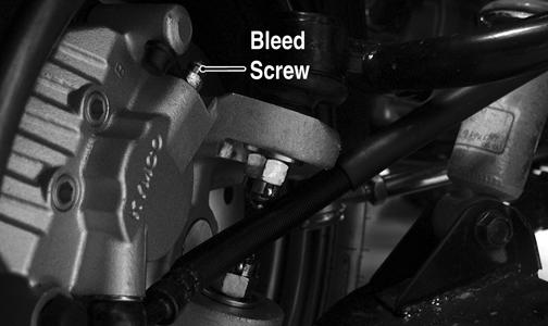
C.Remove the protective cap, install one end of a clear hose onto the REAR bleed screw, and direct the other end into a container; then while holding slight pressure on the brake lever, open the bleed screw and watch for air bubbles. Close the bleed screw before releasing the brake lever. Repeat this procedure until no air bubbles are present.
KM116A
NOTE: During the bleeding procedure, watch the reservoir sight glass very closely to make sure there is always a sufficient amount of brake fluid. Failure to maintain a sufficient amount of fluid in the reservoir will result in air in the system.
D.At this point, perform steps B and C on the FRONT RIGHT bleed screw; then move to the FRONT LEFT bleed screw and follow the same procedure. 4. Carefully check the entire hydraulic brake system that all hose connections are tight, the bleed screws are tight, the protective caps are installed, and no leakage is present.
INSPECTING HOSES Carefully inspect the hydraulic brake hoses for cracks or other damage. If found, the brake hoses must be replaced. CHECKING/REPLACING FRONT PADS The clearance between the brake pads and brake discs is adjusted automatically as the brake pads wear. The only maintenance that is required is replacement of the brake pads when they show excessive wear. Check the thickness of each of the brake pads as follows. 1. Remove a front wheel. 2. Measure the thickness of each brake pad. 3. If thickness of either brake pad is less than 1.0 mm (0.039 in.), the brake pad must be replaced. NOTE: The brake pads should be replaced as a set. 4. To replace the brake pads, use the following procedure.
A.With the wheel removed, remove the brake pad alignment pins from the caliper; then remove the mounting cap screws.
CAUTION
This hydraulic brake system is designed to use DOT 4 brake fluid only. If brake fluid must be added, care must be taken as brake fluid is very corrosive to painted surfaces.
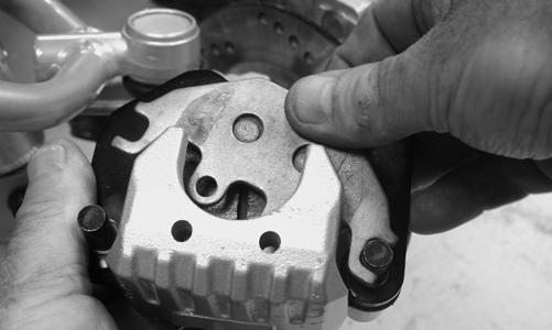
KM265A KM266A B.Remove the caliper from the disc; then compress the caliper holder and remove the brake pads.
KM267 C.Install new brake pads; then install the two brake pad alignment pins.
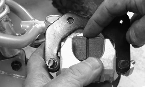
KM268 D.Spread the brake pads and place the brake caliper over the disc. Secure with the mounting cap screws. Tighten the cap screws to 25 ft-lb; then tighten the alignment pins to 13 ft-lb.
KM266A 5. Install the wheel. Tighten in a crisscross pattern to 40 ft-lb. 6. Burnish the brake pads (see Burnishing Brake Pads in this section).
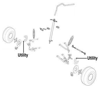
Auxiliary/Rear Hydraulic Brake
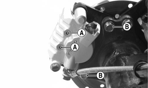
CHECKING 1. With the engine off, the transmission in neutral, and the reverse lever in the forward position, press the brake pedal and attempt to move the ATV. 2. If the rear wheels are locked, it is functioning properly. 3. If the rear wheels are not locked, it must be repaired or bled. BLEEDING To bleed the auxiliary brake, see Hydraulic Brake Systems - CHECKING/BLEEDING in this section. MEASURING/REPLACING REAR BRAKE PADS (Utility) Removing 1. Support the ATV on a suitable support stand. 2. Remove the left rear wheel. 3. Remove the two brake pad alignment pins (A); then remove the mounting cap screws (B).
KM267
Inspecting and Measuring 1. Inspect the pads for gouges, chips, or wear. 2. Inspect the disc for gouges, grooves, cracks, and warpage. 3. Using a calipers, measure the thickness of each brake pad. 4. If the thickness of either brake pad is less than 1.0 mm (0.039 in.), the brake pad must be replaced. NOTE: The brake pads should be replaced as a set. Installing 1. Install new brake pads; then install the two brake pad alignment pins. 2. Spread the brake pads and place the brake caliper over the disc; then secure with the mounting cap screws (B). Tighten the cap screws to 25 ft-lb; then tighten the alignment pins (A) to 13 ft-lb.
KM273A 3. Install the wheel. Tighten in a crisscross pattern to 40 ft-lb. 4. Remove the ATV from the support stand. NOTE: Whenever installing new pads, the new pads must be burnished (see Burnishing Brake Pads in this section).
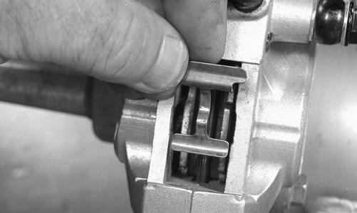
NOTE: The brake caliper on the DVX contains two sets of brake pads. The front pads are controlled by the main brake lever and the rear pads are controlled by the auxiliary brake pedal. 1. Remove the brake pad dust cover; then remove the clip pin and pull the brake pad retaining pin out of the caliper.
KM902B
KM244 2. Remove the brake spring plate; then remove the brake pads.
KM905
Inspecting and Measuring 1. Inspect the pads for gouges, chips, or wear. 2. Inspect the disc for gouges, grooves, cracks, and warpage.
3. Using a calipers, measure the thickness of each brake pad. 4. If the thickness of any brake pad is less than 1.0 mm (0.039 in.), the brake pad must be replaced. NOTE: The brake pads should be replaced as a set. 5. Using a calipers, measure the thickness of the disc. If any portion of the disc is less than 3.00 mm (0.12 in.), the disc must be replaced (see Drive System -
Troubleshooting Brake System). Installing 1. Install the brake pads in the caliper; then insert the brake spring plate.
KM245 2. Install the brake pad retaining pin and secure with the clip pin; then install the dust cover.
KM244
3. Burnish the brake pads.
Burnishing Brake Pads
Brake pads (both hydraulic and auxiliary) must be burnished to achieve full braking effectiveness. Braking distance will be extended until brake pads are properly burnished. To properly burnish the brake pads, use the following procedure.
1. Choose an area large enough to safely accelerate the
ATV to 30 mph and to brake to a stop.
! WARNING
Failure to properly burnish the brake pads could lead to premature brake pad wear or brake loss. Brake loss can result in severe injury.
2. Accelerate to 30 mph; then compress brake lever or apply the auxiliary brake to decelerate to 0-5 mph. 3. Repeat procedure on each brake system five times until brake pads are burnished. 4. Adjust the auxiliary brake (if necessary). 5. Verify that the brakelight illuminates when the hand lever is compressed or the brake pedal is depressed.
Checking/Replacing V-Belt
REMOVING 1. On the Utility, remove the left footwell; then remove the recoil starter assembly. On the DVX, proceed to step 2.
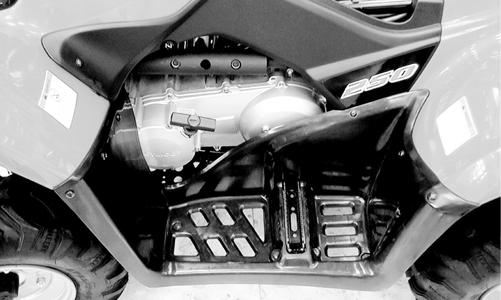
KM279 2. Remove the front and rear V-belt housing cooling ducts. 3. Remove the cap screws securing the V-belt cover noting the location of the different-lengthed cap screws for installing purposes; then using a rubber mallet, gently tap on the cover tabs to loosen the cover. Remove the cover. Account for two alignment pins and one gasket.
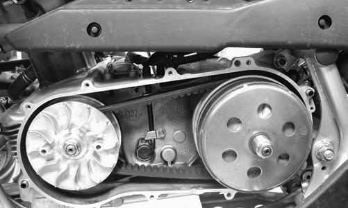
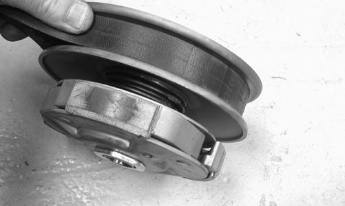
KM253 4. Remove the nut securing the movable drive face; then remove the face. Account for the stepped washer and spacer.
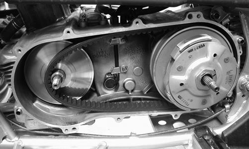
KM276 5. Remove the nut securing the driven pulley; then remove the splined bushing, centrifugal clutch, pulley, and V-belt. INSTALLING 1. Using a rubber mallet, spread the driven pulley sheaves by driving the V-belt down between the sheaves; then slide the driven pulley and V-belt into position.
KM262 2. Install the centrifugal clutch housing onto the driven shaft; then install the splined bushing and secure with the driven pulley retaining nut. Tighten to 40 ftlb.
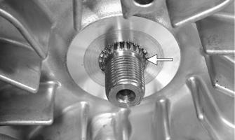
KM276 3. Install the movable drive face onto the crankshaft making sure to “bottom” the sheave out against the center bushing. The crankshaft splines should be visible and the stepped washer should sit over the splines.
KM263A
CAUTION
If the splines are not protruding as shown, the V-belt may be too deep in the drive sheaves. This would cause the drive pulley to be under-tightened and severe drive sheave or crankshaft damage could occur. 4. Secure the movable drive face to the crankshaft with the drive pulley nut and tighten to 72 ft-lb. 5. Install the V-belt cover and tighten the cap screws securely; then connect the cooling boots and tighten the clamps securely.
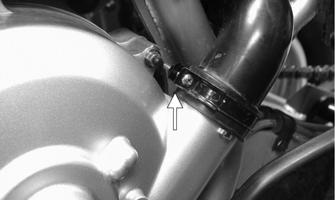
CAUTION
On the DVX, the rear boot clamp must be oriented as shown or interference with heat shielding could occur.
KM252A 6. Install the recoil starter and footwell assembly (Utility). Tighten all hardware securely.