14 minute read
Suspension

The following suspension system components should be inspected periodically to ensure proper operation.
A.Shock absorber rods bent, pitted, or damaged.
B.Rubber damper cracked, broken, or missing.
C.Shock absorber body damaged, punctured, or leaking.
D.Shock absorber eyelets broken, bent, or cracked.
E.Shock absorber eyelet bushings worn, deteriorated, cracked, or missing.
F.Shock absorber spring broken or sagging.
G.Sway bar mountings tight and bushings secure. SPECIAL TOOL
A special tool must be available to the technician when performing service procedures in this section. Refer to the current Special Tools Catalog for the appropriate tool description.
Description p/n
Spring Removal Tool 0644-057
NOTE: Special tools are available from the Arctic
Cat Service Department.
Front Shock Absorbers
REMOVING
1.Secure the vehicle on a support stand to elevate the wheels and to release load on the suspension.
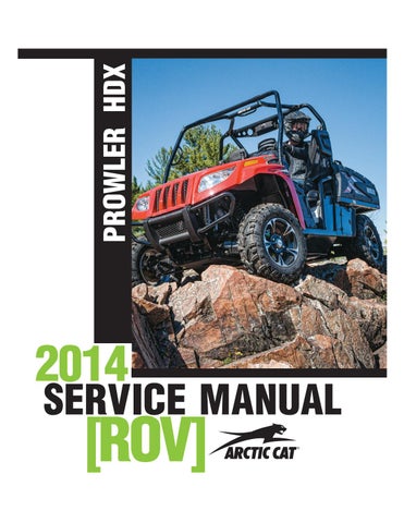
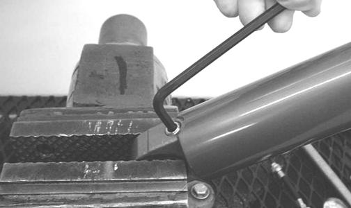
2.Remove the two cap screws and nuts securing each front shock absorber to the frame and upper A-arm.
Account for bushings and sleeves from each.
! WARNING
Make sure the vehicle is solidly supported on the support stand to avoid injury.
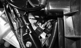
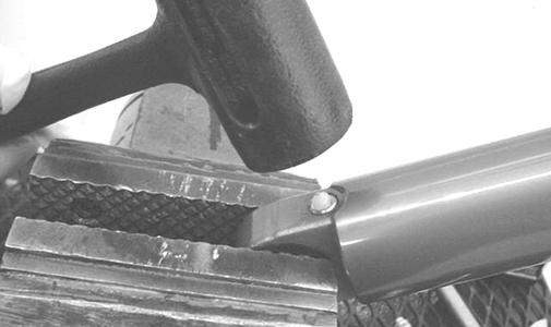
3.Using a suitable spring compression stand, compress the shock absorber spring, remove the retainer, and remove the spring.
! WARNING
Shock absorber springs are under high compression loads. Do not attempt to remove springs without an adequate spring compressor. Sever injury could result.
CF341
CLEANING AND INSPECTING
1.Clean all shock absorber components in parts-cleaning solvent. 2.Inspect each shock rod for nicks, pits, rust, bends, and oily residue. 3.Inspect all springs, spring retainers, shock rods, sleeves, bushings, shock bodies, and eyelets for cracks, leaks, and bends. INSTALLING
1.Place the shock absorber spring over the shock absorber, compress the spring, and install the retainer. 2.Place bushings and sleeves (where appropriate) into shock eyelet; then install shocks with two cap screws and nuts.
3.Tighten the front shock absorber cap screws to 35 ftlb.
4.Remove the vehicle from the support stand.
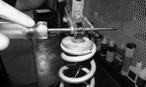
Rear Shock Absorbers
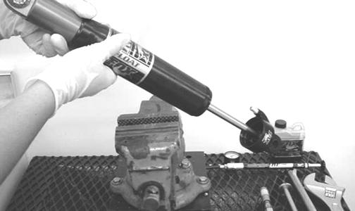
The rear shock absorbers are Fox Air shocks with springover feature incorporating fixed pre-load coil springs over variable pressure air shocks. REMOVING
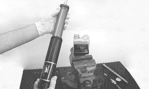
1.Secure the vehicle on a support stand to elevate the wheels and to release load on the suspension.
! WARNING
Make sure the vehicle is solidly supported on the support stand to avoid injury.
3.Using a suitable spring compressor, compress the spring and retainer ring from the lower shock body. 4.Carefully release the spring pressure and remove the spring. Account for the spring retainer. DISASSEMBLING
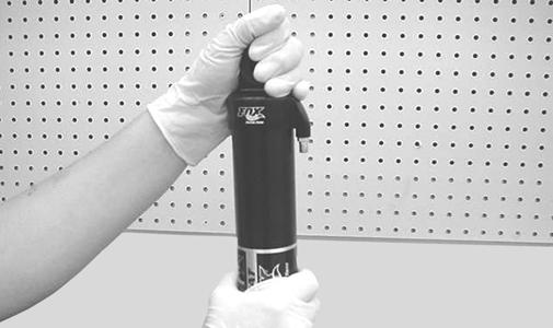
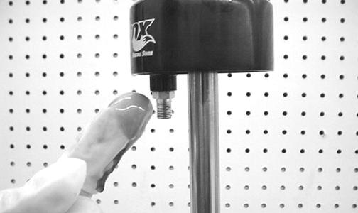
1.Remove the valve cap; then bleed the air from the air chamber. ! WARNING
Always wear latex or rubber gloves when servicing a shock absorber with shock oil.
FS141
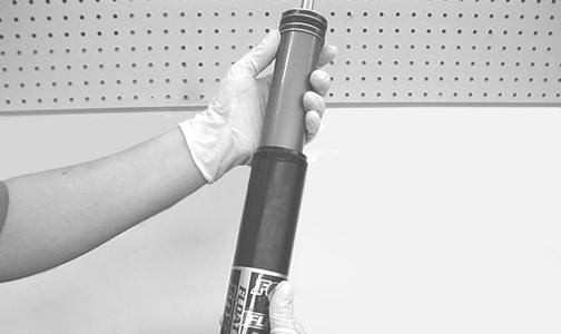
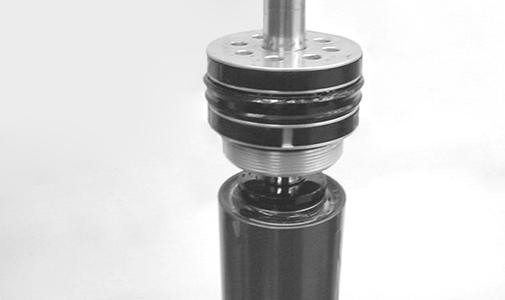
2.While holding the end cap; unscrew the air chamber.
FS142
3.Drain the oil from the air chamber.
FS143 FS144
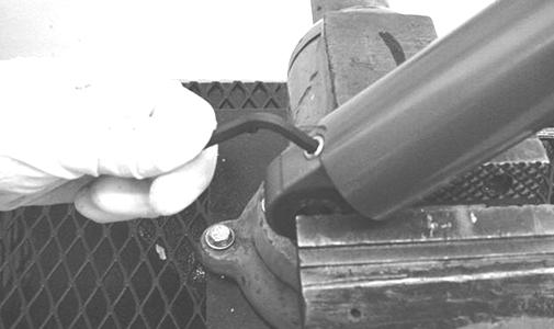
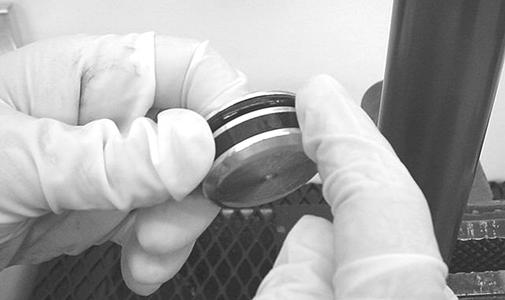
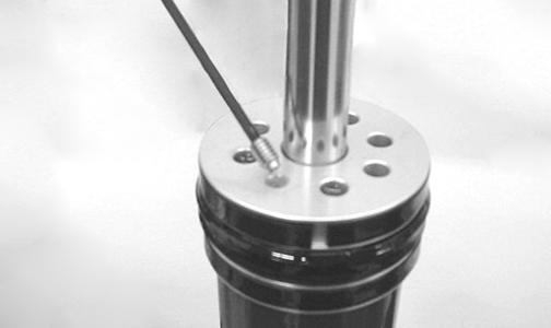
5.Using a pick, remove the air valve ball from the nitrogen bladder.
FS145A
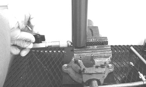
6.Using an Allen-wrench, loosen the nitrogen bladder ½ turn.
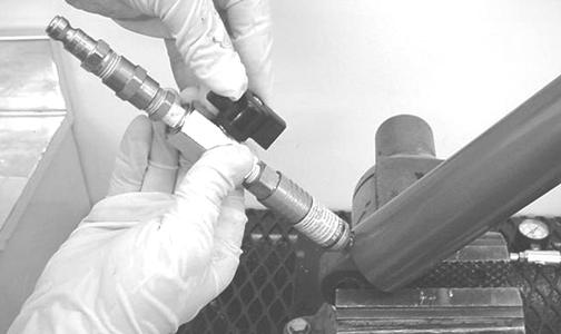
FS146
7.Using Inflation Needle (p/n 0744-020), remove all the nitrogen from the shock.
FS147
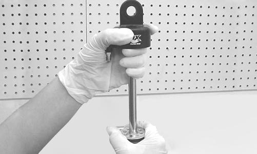
8.Using a 5/64-in. Allen-wrench, remove the set screw from the bearing cap.
FS148
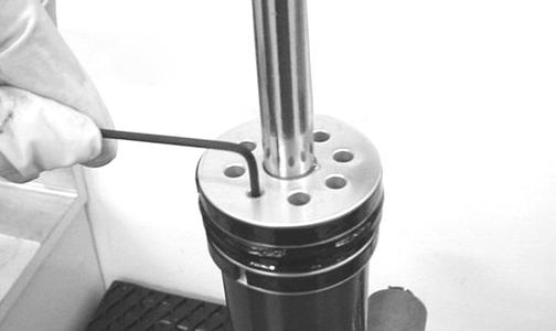
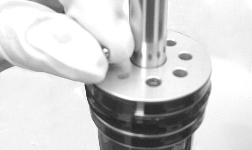
9.Using a magnet held against the Allen-wrench, remove the bleed ball.
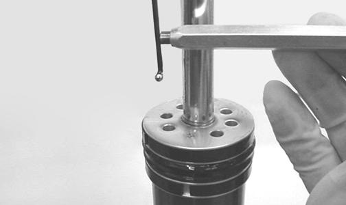
FS149
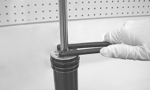
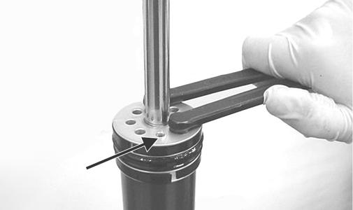
10.Using Spanner Wrench (p/n 0644-453), loosen the bearing cap.
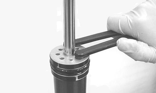
FS151
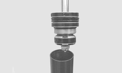
12.Drain the oil from the shock body into a suitable container.
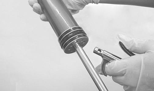
13.Using an appropriate floating piston removal tool, remove the floating piston.
FS152
NOTE: For ease in removing the piston, use the
inflation needle to help vent the shock body.
FS153
14.Clean and inspect all components. ASSEMBLING/CHARGING 1.Lubricate the O-ring and wiper on the floating piston with shock oil.
FS154
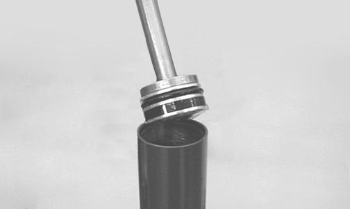
2.Carefully install the floating piston into the shock body until it is below the threads.
FS155
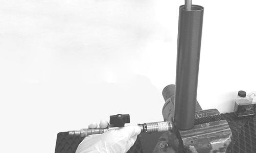
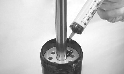
3.Using an appropriate location tool, install the floating piston to a depth of 7.0 in. while using the inflation needle to vent the shock body.
FS156
4.Using Fox Racing Shock Oil, fill the shock body to the bottom of the threads; then, allow to sit 1-2 minutes to ensure no air is in the oil.
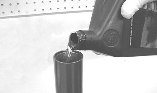
FS157
5.Lubricate the O-ring on the underside of the end cap with shock oil.
FS158
6.Lower the shock rod into the shock body until the piston is submerged in oil.
FS159
7.While keeping the shock rod fully extended, thread the bearing cap into position.
FS161
NOTE: When tightening the bearing cap, note air
and excess oil being bled from the hole in the cap.
FS150A
9.Install the bleed ball and set screw into the bearing cap.
FS162 FS164
11.Using a 3/16-in. Allen-wrench, tighten the nitrogen bladder.
FS165
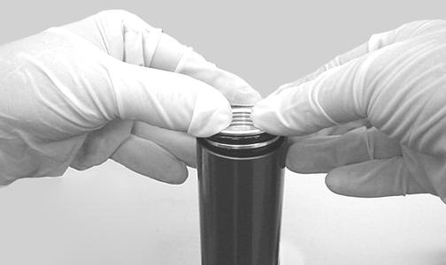
12.Install the air valve ball by gently tapping it with a plastic mallet.
FS166
13.Test the shock for proper operation. 14.Using compressed air, blow all oil from the holes in the bearing cap.
FS167
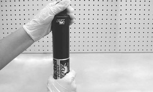
15.Lubricate the seal on the air chamber with Fox Float
Fluid.
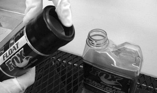
FS168
16.Slide the air chamber onto the shock body.
FS169
17.Add 1 cc of Fox Float Fluid into the chamber.
FS170 FS171
NOTE: Prior to installing the air chamber, make sure
the end cap O-ring is properly positioned in the chamber.
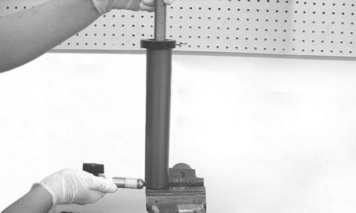
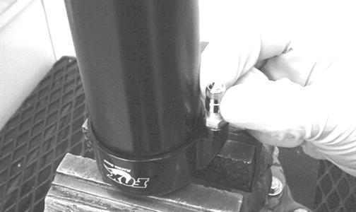
19.Invert the shock and secure by the end cap to assure the air chamber is tight.
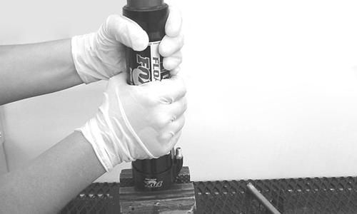
FS172
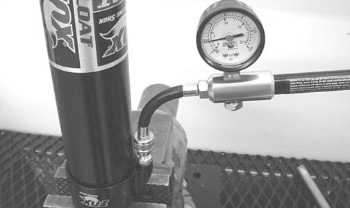
20.Using a hand pump, inflate the air chamber to the appropriate pressure.
Payload Pressure
0-250 lb 15 psi 250-500 lb 60 psi (min) 500-750 lb 90 psi (min) 750-1000 lb 150 psi
FS173
! WARNING
FS174
22.Install the spring using an appropriate spring compressor and secure with the retaining ring. INSTALLING
1.Install the shock absorber (valve stem at the top) and secure with the cap screws. Tighten new lock nuts to 35 ft-lb.
2.Lower the vehicle to the ground.
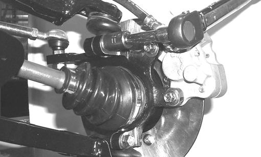
Front A-Arms
REMOVING
1.Secure the vehicle on a support stand to elevate the front wheels; then remove the wheels.
2.Remove the cotter pin from the nut. Discard the cotter pin. ! WARNING
Make sure the vehicle is solidly supported on the support stand to avoid injury.

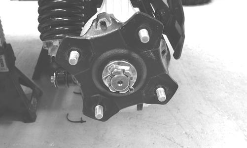
PR257
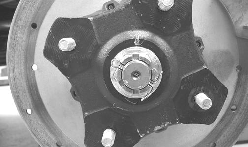
3.Remove the nut securing the hub. 4.Remove the brake caliper. Account for two cap screws.
CD007
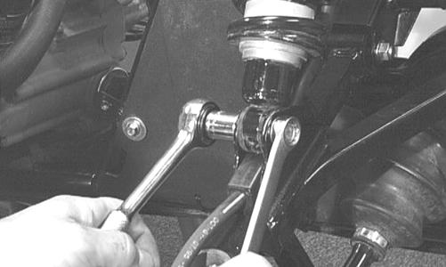
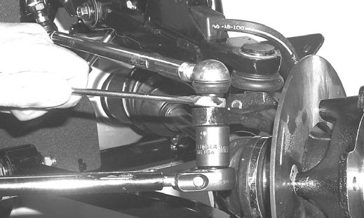
5.Remove the hub assembly. 6.Remove the cotter pin and slotted nut securing the tie rod end to the knuckle; then remove the tie rod end from the knuckle.
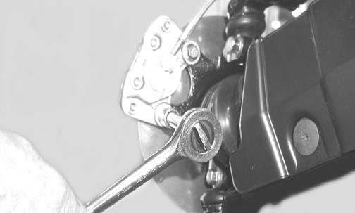
7.Remove the cap screws securing the ball joints to the knuckle.
CAUTION
Support the knuckle when removing the cap screws or damage to the threads will occur.
PR193
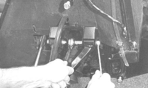
8.Tap the ball joints out of the knuckle; then remove the knuckle.
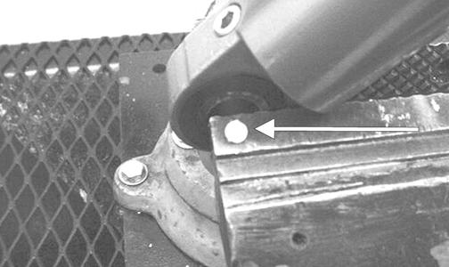
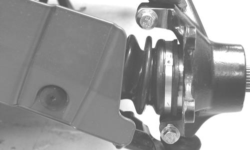
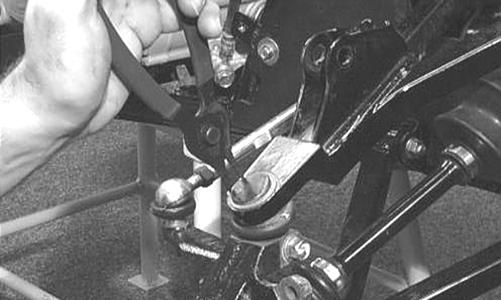
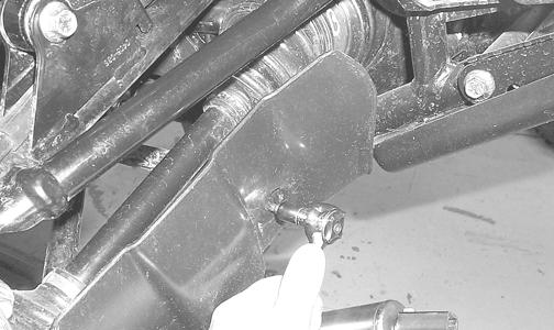
9.Remove the lower shock absorber eyelet from the upper A-arm.
AF626D
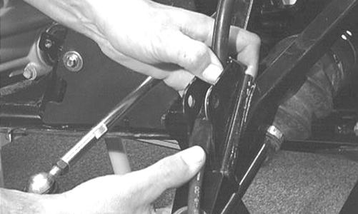
10.Remove the cap screws securing the A-arms to the frame.
AF610D
11.Remove the snap ring from the ball joint; then remove the ball joint from the A-arm.
AF616D
CLEANING AND INSPECTING
1.Clean all A-arm components in parts-cleaning solvent. 2.Clean the ball joint mounting hole of all residual Loctite, grease, oil, or dirt for installing purposes. 3.Inspect the A-arm for bends, cracks, and worn bushings. 4.Inspect the ball joint mounting holes for cracks or damage. 5.Inspect the frame mounts for signs of damage, wear, or weldment damage. INSTALLING
1.Apply Loctite Primer “T” to the A-arm socket; then apply green Loctite #609 to the entire outside diameter of the ball joint. Install the ball joint into the A-arm and secure with the snap ring.
AF616D
2.Install the A-arm assemblies into the frame mounts and secure with the cap screws. Only finger-tighten at this time.
AF610D
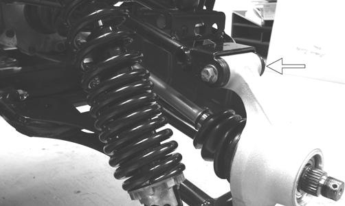
3.Route the brake hose through the upper A-arm shock absorber mount.
AF627D
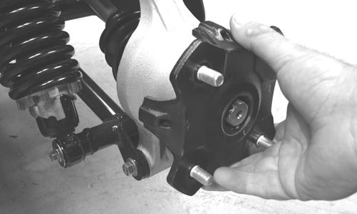
4.Secure the lower eyelet of the shock absorber to the upper A-arm. Tighten nut to 20 ft-lb. 5.Secure the A-arm assemblies to the frame mounts (from step 2). Tighten the cap screws to 35 ft-lb. 6.Install the knuckle assembly onto the ball joints and secure with cap screws. Tighten to 35 ft-lb.
AF628D
7.Install the tie rod end and secure with the nut (coated with red Loctite #271). Tighten to 30 ft-lb; then install a new cotter pin and spread the pin to secure the nut. NOTE: During assembly, new cotter pins should
be installed.
AF618D
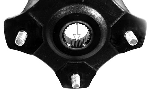
8.Apply grease to the hub and drive axle splines; then install the hub assembly onto the drive axle.
PR290A
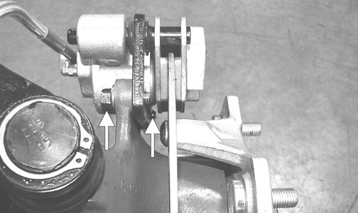
9.Secure the hub assembly with the nut. Tighten only until snug. 10.Secure the brake caliper holder to the knuckle with two new “patch-lock” cap screws. Tighten to 20 ft-lb.
PR377B
11.Secure the hub nut (from step 9) to the shaft/axle.
Tighten to 200 ft-lb. 12.Install a new cotter pin and spread the pin to secure the nut.
NOTE: If the cotter pin cannot be inserted due to
misalignment of the hole in the axle and the slots in the nut, tighten the nut until properly aligned.
PR260
13.Install the wheel and tighten in 20 ft-lb increments to 40 ft-lb (steel wheel) or 80 ft-lb (aluminum wheel). 14.Remove the vehicle from the support stand.
Rear A-Arms
REMOVING
1.Secure the vehicle on a support stand to elevate the wheels.
2.Place the transmission in park. 3.Remove the wheel.
4.Remove the cotter pin securing the hex nut; then remove the hex nut.
! WARNING
Make sure the vehicle is solidly supported on the support stand to avoid injury.
5.Remove the cap screws and lock nut securing the shock absorber to the frame and lower A-arm; then remove the shock absorber.
6.Remove the cap screws securing the boot guard to the lower A-arm.
AF934
7.Slide the axle out of the knuckle and set aside.
8.Remove the cap screws and lock nuts securing the knuckle to the A-arms. Discard the lock nuts.
PR220A
NOTE: Never reuse a lock nut. Once a lock nut has been removed, it must be replaced with a new lock nut.
9.Remove the cap screws and lock nuts securing the Aarms to the frame; then remove the A-arms. CLEANING AND INSPECTING
1.Clean all A-arm components in parts-cleaning solvent. 2.Inspect the A-arm for bends, cracks, and worn bushings. 3.Inspect the frame mounts for signs of damage, wear, or weldment damage. INSTALLING
1.Install the A-arm assemblies into the frame mounts and secure with the cap screws and new lock nuts.
Finger-tighten only at this time. 2.Slide the knuckle onto the drive axle and into position on the A-arms; then secure the knuckle to the A-arms with cap screws and new lock nuts. Tighten to 35 ft-lb. 3.Tighten the hardware securing the A-arms to the frame mounts (from step 1) to 33 ft-lb.
PR221
5.Secure the hub assembly with the nut. Tighten to 200 ft-lb.
6.Install a new cotter pin and spread the pin to secure the nut.
NOTE: If the cotter pin cannot be inserted due to
misalignment of the hole in the axle and the slots in the nut, tighten the nut until properly aligned.
PR196
7.Secure the shock absorber to the frame with a cap screw and new lock nut. Tighten to 35 ft-lb. 8.Secure the shock absorber to the lower A-arm with a cap screw and new lock nut. Tighten to 35 ft-lb. 9.Secure the boot guard to the lower A-arm with the two cap screws. Tighten securely. 10.Install the wheel and tighten in 20 ft-lb increments to 40 ft-lb (steel wheel) or 80 ft-lb (aluminum wheel). 11.Remove the vehicle from the support stand.
Wheels and Tires
TIRE SIZE
! WARNING
Use only Arctic Cat approved tires when replacing tires. Failure to do so could result in unstable vehicle operation.
This vehicle is equipped with low-pressure tubeless tires of the size and type listed in the General Information section. Do not under any circumstances substitute tires of a different type or size.
! WARNING
Always use the size and type of tires specified. Always maintain proper tire inflation pressure.
! WARNING
Do not mix tire tread patterns. Use the same pattern type on front and rear. Failure to heed warning could cause poor handling qualities of the vehicle and could cause excessive drive train damage not covered by warranty.
TIRE INFLATION PRESSURE
Front and rear tire inflation pressure should be 1.41 kg/ cm² (20 psi). REMOVING
1.Secure the vehicle on a support stand to elevate the wheels.
! WARNING
Make sure the vehicle is solidly supported on the support stand to avoid injury.
CLEANING AND INSPECTING
1.Clean the wheels and hubs with parts-cleaning solvent.
2.Clean the tires with soap and water. 3.Inspect each wheel for cracks, dents, or bends. 4.Inspect each tire for cuts, wear, missing lugs, and leaks.
INSTALLING
1.Install each wheel on its hub and secure with the existing hardware.
2.Tighten in 20 ft-lb increments to 40 ft-lb (steel wheel) or 80 ft-lb (aluminum wheel). CHECKING/INFLATING
1.Using an air pressure gauge, measure the air pressure in each tire. Adjust the air pressure as necessary to meet the recommended inflation pressure. 2.Inspect the tires for damage, wear, or punctures.
! WARNING
Do not operate the vehicle if tire damage exists.
NOTE: If repair is needed, follow the instructions
found on the tire repair kit or remove the wheel and have it repaired professionally.
NOTE: Be sure all tires are the specified size and
have identical tread pattern.
Troubleshooting
Problem: Suspension too soft Condition Remedy
1. Spring preload incorrect 1.Adjust preload 2. Spring(s) weak 2.Replace spring(s) 3. Shock absorber damaged 3.Replace shock absorber 4. Rear shock absorbers too soft 4.Check and adjust air pressure in shocks
Problem: Suspension too stiff Condition Remedy
1. Spring preload incorrect 1.Adjust preload 2. A-arm-related bushings worn 2.Replace bushing
Problem: Suspension noisy Condition Remedy
1. Cap screws (suspension system) loose 1.Tighten cap screws 2. A-arm-related bushings worn 2.Replace bushings
Problem: Vehicle pulling or steering erratic Condition Remedy
1. Vehicle steering is erratic on dry, level surface 1.Check front wheel alignment and adjust if necessary (see the Steering/Frame/Controls - Checking/Adjusting Front Wheel 2. Vehicle pulls left or right on dry, level surface Alignment) 2.Check air pressure in tires and adjust to specifications
Printed in U.S.A. Trademarks of Arctic Cat Inc., Thief River Falls, MN 56701 p/n 2259-861