38 minute read
Electrical System

SPECIAL TOOLS
A number of special tools must be available to the technician when performing service procedures in this section. Refer to the current Special Tools Catalog for the appropriate tool description.
Description p/n
Fluke Model 73 Multimeter 0644-191 Fluke Model 77 Multimeter 0644-559 Timing Light 0644-296 MaxiClips 0744-041 Peak Voltage Reading Adapter 0644-307 Test Plug/Code List 0486-219
NOTE: Special tools are available from the Arctic
Cat Service Department.
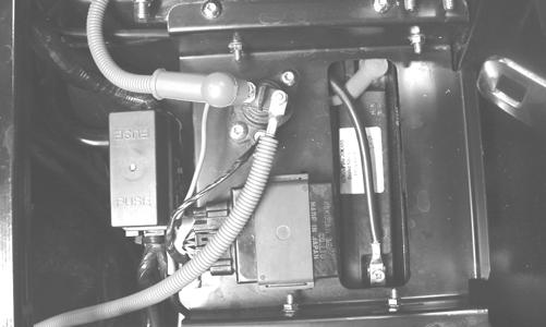
Battery
The battery is located under the seat. After being in service, batteries require regular cleaning and recharging in order to deliver peak performance and maximum service life. The following procedures are recommended for cleaning and maintaining lead-acid batteries. Always read and follow instructions provided with battery chargers and battery products. NOTE: Refer to all warnings and cautions provided
with the battery or battery maintainer/charger.
Loss of battery charge may be caused by ambient temperature, ignition OFF current draw, corroded terminals, self discharge, frequent start/stops, and short engine run times. Frequent winch usage, snowplowing, extended low RPM operation, short trips, and high amperage accessory usage are also reasons for battery discharge. Maintenance Charging NOTE: Arctic Cat recommends the use of the CTEK
Multi US 800 or the CTEK Multi US 3300 for battery maintenance charging. Maintenance charging is required on all batteries not used for more than two weeks or as required by battery drain.
1.When charging a battery in the vehicle, be sure the ignition switch is in the OFF position. NOTE: Be sure to maintain the fluid of the battery at
the UPPER LEVEL. Use only distilled water when adding fluid to these batteries.
2.Clean the battery terminals with a solution of baking soda and water.
3.Be sure the charger and battery are in a well-ventilated area and ensure the battery charger cables will not contact any battery acid. Be sure the charger is unplugged from the 110-volt electrical outlet. 4.Connect the red terminal lead from the charger to the positive terminal of the battery; then connect the black terminal lead of the charger to the negative terminal of the battery. NOTE: Optional battery charging adapters are avail-
able from your authorized Arctic Cat dealer to connect directly to your vehicle from the recommended chargers to simplify the maintenance charging process. Check with your authorized Arctic Cat dealer for proper installation of these charging adapter connectors.
5.Plug the battery charger into a 110-volt electrical outlet.
6.If using the CTEK Multi US 800, there are no further buttons to push. If using the CTEK Multi US 3300, press the Mode button (A) at the left of the charger until the Maintenance Charge Icon (B) at the bottom illuminates. The Normal Charge Indicator (C) should illuminate on the upper portion of the battery charger.
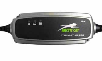
800E
NOTE: The maintainer/charger will charge the battery
to 95% capacity at which time the Maintenance Charge Indicator (D) will illuminate and the maintainer/charger will change to pulse/float maintenance. If the battery falls below 12.9 DC volts, the charger will automatically start again at the first step of the charge sequence.
3300A
NOTE: Not using a battery charger with the proper
float maintenance will damage the battery if connected over extended periods.
Charging NOTE: Arctic Cat recommends the use of the CTEK
Multi US 800 or the CTEK Multi US 3300 for battery maintenance charging.
1.Be sure the battery and terminals have been cleaned with a baking soda and water solution. 2.Be sure the charger and battery are in a well-ventilated area and ensure the battery charger cables will not contact any battery acid. Be sure the charger is unplugged from the 110-volt electrical outlet. 3.Connect the red terminal lead from the charger to the positive terminal of the battery; then connect the black terminal lead of the charger to the negative terminal of the battery. 4.Plug the charger into a 110-volt electrical outlet. 5.By pushing the Mode button (A) on the left side of the charger, select the Normal Charge Icon (E). The
Normal Charge Indicator (C) should illuminate on the upper left portion of the charger. 6.The battery will charge to 95% of its capacity at which time the Maintenance Charge Indicator (D) will illuminate.
NOTE: For optimal charge and performance, leave the
charger connected to the battery for a minimum 1 hour after the Maintenance Charge Indicator (D) illuminates. If the battery becomes hot to the touch, stop charging. Resume after it has cooled.
7.Once the battery has reached full charge, unplug the charger from the 110-volt electrical outlet. NOTE: If, after charging, the battery does not perform
to operator expectations, bring the battery to an authorized Arctic Cat dealer for further troubleshooting.
RPM Limiter
NOTE: The ROV is equipped with an ECU that retards ignition timing when maximum RPM is approached. When the RPM limiter is activated, it could be misinterpreted as a high-speed misfire.
Testing Electrical Components
All of the electrical tests should be made using the Fluke Model 73 Multimeter or Model 77 Multimeter and when testing peak voltage, the Peak Voltage Reading Adapter must be used. If any other type of meter is used, readings may vary due to internal circuitry. When troubleshooting a specific component, always verify first the fuse(s) are good, the bulb(s) are good, the connections are clean and tight, the battery is fully charged, and all appropriate switches are activated.
Switches
Each time the vehicle is used, switches should be checked for proper operation. Use the following list for reference.
A.Ignition/start switch — engine will run; starter will engage. B.Drive select switch — differential will engage (4WD)/disengage (2WD). C.Reverse/neutral/high/low switch — R/N/H/L will be indicated on the LCD.
D.Headlight switch — high beam, low beam, and lights off can be selected. E.Brake switch — brakelight illuminates and starter can be engaged with vehicle in gear.
Electrical Connections
The electrical connections should be checked periodically for proper function. In case of an electrical failure, check fuses, connections (for tightness, corrosion, damage), and/or bulbs.
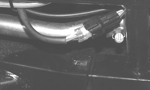
Accessory Receptacle/ Connector
NOTE: This test procedure is for either the recep-
tacles or the connectors.
VOLTAGE
1.Turn the ignition switch to the ON position; then set the meter selector to the DC Voltage position. 2.Connect the red tester lead to the red/white wire or the positive connector; then connect the black tester lead to ground. 3.The meter must show battery voltage. NOTE: If the meter shows no battery voltage,
troubleshoot the battery, fuse, receptacle, connector, or the main wiring harness.
Brakelight Switch
VOLTAGE (Wiring Harness Connector)
1.Set the meter selector to the DC Voltage position. 2.Connect the red tester lead to the orange wire; then connect the black tester lead to ground.
PR276A
3.The meter must show battery voltage. NOTE: If the meter shows no battery voltage,
troubleshoot the battery, fuse, switch, or the main wiring harness.
NOTE: If the meter shows battery voltage, the
main wiring harness is good; proceed to test the switch/component, the connector, and the switch wiring harness for resistance.
RESISTANCE (Switch Connector)
CAUTION
Always disconnect the battery when performing resistance tests to avoid damaging the multimeter.
NOTE: The brake pedal must be depressed for
this test.
1.Set the meter selector to the OHMS position. 2.Connect the red tester lead to one black wire; then connect the black tester lead to the other black wire.
NOTE: If the meter shows more than 1 ohm of
resistance, replace the switch.
Engine Coolant Temperature (ECT) Sensor
1.Connect the meter leads (selector in OHMS position) to the sensor terminals.
2.Suspend the sensor and a thermometer in a container of cooking oil; then heat the oil. NOTE: Neither the sensor nor the thermometer
should be allowed to touch the bottom of the container or inaccurate readings will occur. Use wire holders to suspend the sensor and thermometer.
! WARNING
Wear insulated gloves and safety glasses. Heated oil can cause severe burns.
3.On the ECT sensor when the temperature reaches 40° C (104° F), the meter should read approximately 1136 ohms.
4.On the ECT sensor when the temperature reaches 100° C (212° F), the meter should read approximately 155 ohms. 5.If the readings are not as indicated, the sensor must be replaced. 6.Install the sensor and tighten securely. 7.Connect the leads.
Fan Motor
RESISTANCE (Fan Motor Connector)
1.Set the meter selector to the OHMS position. 2.Connect the red tester lead to the red wire; then connect the black tester lead to the black wire.
PR183A
3.The meter must show less than 1 ohm.
NOTE: If the meter shows more than 1 ohm of resistance, troubleshoot or replace the fan motor.
NOTE: To determine if the fan motor is good, con-
nect the red wire from the fan connector to a 12 volt battery; then connect the black wire from the fan connector to ground. The fan should operate.
! WARNING
Care should be taken to keep clear of the fan blades.
Power Distribution Module (PDM)
NOTE: The module and wiring harness are not a
serviceable component and must be replaced as an assembly.
If there is any type of electrical system failure, always check the fuses first.
NOTE: The fuses are located in a power distribu-
tion module under the operator’s seat.
1.Remove all fuses from the power distribution module.
NOTE: To remove a fuse, compress the locking
tabs on either side of the fuse case and lift out.
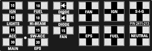
2411-213
CAUTION
Always replace a blown fuse with a fuse of the same type and rating.
NOTE: Make sure the fuses are returned to their
proper position according to amperage. Refer to the amperage listed under each fuse on the power distribution module.
2.Set the meter selector to the DC Voltage position. 3.Connect the black tester lead to ground. 4.Using the red tester lead, contact each end of the fuse holder connector terminals individually. 5.The meter must show battery voltage from one side of the connector terminal ends.
NOTE: Battery voltage will be indicated from only
one side of the fuse holder connector terminal; the other side will show no voltage.
NOTE: When testing the HI fuse holder, the head-
light OFF/HI/LO switch must be in the HI position; when testing the LIGHTS fuse holder, the headlight dimmer switch can be in either the HI or the LO position.
NOTE: If the meter shows no battery voltage,
troubleshoot the battery, switches, power distribution module, or the main wiring harness.
RELAYS
The 4-pin relays are indentical plug-in type located on the power distribution module. Relay function can be checked by switching relay positions. The 4-pin relays are interchangeable.
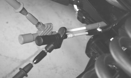
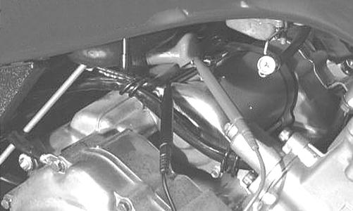
Ignition Coil
The ignition coil is mounted on the fuel pump mounting plate adjacent to the fuel pump. VOLTAGE (Primary Side) See Primary Coil in this sub-section. RESISTANCE
CAUTION
Always disconnect the battery when performing resistance tests to avoid damaging the multimeter.
NOTE: For these tests, the meter selector should
be set to the OHMS position.
Primary Winding 1.Connect the red tester lead to the terminal (with the wire removed); then connect the black tester lead to ground.
PR278A
2.The meter reading must be within specification. Secondary Winding 1.Connect the red tester lead to the high tension lead (with the plug cap removed); then connect the black tester lead to ground. 2.The meter reading must be within specification. NOTE: If the meter does not show as specified,
replace ignition coil.
Spark Plug Cap 1.Connect the red tester lead to one end of the cap; then connect the black tester lead to the other end of the cap.
AR603D
2.The meter reading must be within specification. NOTE: If the meter does not show as specified,
replace the spark plug cap.
VOLTAGE
Primary Coil 1.Set the meter selector to the DC Voltage position; then disconnect the two wires from the coil.
NOTE: The coil is located to the right of the
engine and may be accessed from behind the right-side seat with the cargo box raised.
2.Connect the red tester lead to the orange wire and the black tester lead to the blue/white wire.
EFI Sensors/Components
CRANKSHAFT POSITION (CKP) SENSOR
To test the CKP sensor, see Stator Coil/Crankshaft Position (CKP) Sensor in this section. MANIFOLD ABSOLUTE PRESSURE (MAP) SENSOR
1.Disconnect the MAP connector from the pressure sensor located on the throttle body. 2.Select DC Voltage on the tester and turn the ignition switch to the ON position. 3.Connect the black tester lead to the black/green wire and the red tester lead to the orange/blue wire. The meter should read 4.5-5.5 DC volts. If the meter does not read as specified, check the ECU connector or wiring. 4.Connect the MAP to the harness; then using Maxi-
Clips, connect the red tester lead to the brown/white wire and the black tester lead to the black/green wire.
With the engine running at idle speed, the meter should read approximately 1.5 DC volts. NOTE: If the meter does not read as specified,
replace the sensor.
Speed Sensor
NOTE: Prior to testing the speed sensor, inspect
the three-wire connector on the speed sensor for contamination, broken pins, and/or corrosion.
1.Set the meter selector to the DC Voltage position. 2.With appropriate needle adapters on the meter leads, connect the red tester lead to the voltage lead (V); then connect the black tester lead to the ground lead (G).
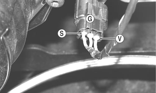
3.Turn the ignition switch to the ON position. 4.The meter must show approximately 6 DC volts. 5.Leave the black tester lead connected; then connect the red tester lead to the signal lead pin (S). 6.Slowly move the vehicle forward or backward; the meter must show 0 and approximately 6 DC volts alternately. NOTE: If the sensor tests are within specifica-
tions, the LCD gauge must be replaced (see Steering/Frame/Controls section).
To replace a speed sensor, use the following procedure. 1.Disconnect the three-wire connector from the speed sensor harness or from the speed sensor; then remove the Allen-head cap screw securing the sensor to the sensor housing. 2.Remove the sensor from the sensor housing accounting for an O-ring.
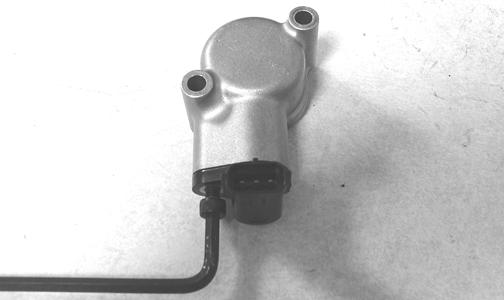
CD070
3.Install the new speed sensor into the housing with new O-ring lightly coated with multi-purpose grease; then secure the sensor with the Allen-head cap screw (threads coated with blue Loctite #242). Tighten securely.
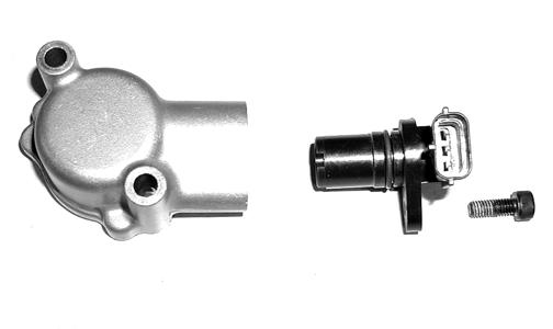
CD071
Electronic Power Steering (EPS)
The electronic power steering (EPS) system is an electromechanical device that utilizes 12 volt DC power to drive a motor linked to the steering shaft to assist the driver when rotating the steering wheel. Driver steering inputs are detected by a torque-sensing transducer assembly within the EPS housing. These inputs are converted to electronic signals by the transducer and control circuitry to tell the motor which way to drive the steering shaft. When no steering input (pressure on the steering wheel) is detected, no torque signal is generated, and no steering assist is provided by the motor. The EPS system is battery-system powered; therefore, the battery must be in good condition and fully charged. Power delivery and overload protection is provided by an EPS relay and 30-amp fuse, located under the seat in the Power Distribution Module (PDM). If a system malfunction occurs, a malfunction code “P0635” will be displayed on the LCD gauge. Initially, the gauge will go blank for 30 seconds and the code will flash: then the gauge will return to normal except the code will continue to be displayed. The following is a list of conditions that can generate a malfunction code. All conditions with the exception of item 5 are external to the EPS assembly and therefore can be cleared without replacement of the EPS assembly. Make sure to thoroughly troubleshoot the entire system before replacing the EPS assembly. NOTE: The EPS assembly is not serviceable and no
service parts or parts lists are available. The EPS is only serviceable as an assembly and must not be disassembled or EPS warranty will be voided.
Malfunction code P0635 will appear if one of the following six conditions occur: 1.Battery system power failure:
A.30 amp EPS fuse blown
B.EPS relay failure
C.EPS voltage less than 8.5 DC volts for more than two seconds
2.Ignition switch ON for more than five minutes with the engine not running. 3.Vehicle Speed Signal Malfunction (engine speed must exceed 2700 RPM for more than 60 seconds to generate a malfunction code - timer resets if engine drops below 2700 RPM).
A.Diode defective (open or shorted)
CAUTION
Do not attempt to check resistance of the EPS motor (2-pin input receptacle). There are internal capacitors holding a charge that can cause internal damage to an ohmmeter.
D.Speed sensor defective
E.Speed sensor signal erratic
F.Speed sensor signal present but without engine speed signal
G.Speed sensor power from LCD gauge interrupted
H.Incorrect LCD gauge installed 4.Engine Speed Signal Malfunction (vehicle speed must exceed 5 MPH for more than two seconds - timer resets if speed drops below 5 MPH.
A.No engine speed signal
B.Erratic engine speed signal 5.EPS Control Circuit Malfunction.
The following procedures may be helpful in determining the source of a malfunction code:
Condition: Ignition Key Switch ON and NO EPS assist when moving the handlebar. Code “P0635” flashing. NOTE: Prior to troubleshooting below, make sure
that Ignition Key Switch has not been left on with the engine not started. After five minutes, this will deactivate the EPS and display the malfunction code. Turn Ignition Key Switch OFF and back to ON to reset and reactivate the EPS. If code and symptom persists, continue as follows:
1.Check 30 amp EPS fuse. 2.Check EPS relay (may be switched with any other 4pin relay on PDM - replace relay if EPS normal after switching). 3.Disconnect 2-pin connector on the EPS assembly and connect a volt meter set to DC voltage to the harness (black meter lead to BLK and red meter lead to ORG/
BRN) With the ignition switch to the ON position, the meter must read more than 8.5 DC volts (if correct voltage is not present, check connections and wiring harness - if correct voltage is present, replace EPS assembly - see the Steering/Frame/Controls section).
CAUTION
Do not attempt to disassemble the EPS assembly as there are no serviceable components within the assembly and damage will occur voiding the EPS warranty.
Condition: Ignition switch ON and EPS assist normal when moving handlebar. Code “P0635” flashing. 1.Check for speed sensor signal by disconnecting the 8-pin connector from the EPS assembly and using a multi-meter set to the DC volt position, connect the black lead to the PNK/YEL wire and the red lead to the ORG wire. With the ignition switch turned to the
ON position, slowly move the vehicle forward or backward. The meter must alternate from 0 DC volts to approximately 12 DC volts. If meter readings are not as specified: A.Check EPS diode for correct installation or open diode (replace diode or install correctly).
B.Check speed sensor using procedure found in this section (replace speed sensor/install proper gauge). 2.Check for engine speed signal by disconnecting the 8-pin connector from the EPS assembly and using a multi-meter set to the AC voltage position, connect one lead to any BLK wire and the other lead to YEL/
VLT wire. Start the engine and with the engine idling the meter should read approximately 7.5 AC volts. If meter reading is not as specified:
A.Check the wiring harness from EPS to gauge (YEL/VLT wire - repair wiring).
B.Check the AC generator using the procedure in this section. If not to specifications, replace the stator coil.
If after completing the above checks with normal results and malfunction code “P0635” persists, the EPS assembly must be replaced. To replace the EPS assembly, see the Steering/Frame/Controls section.
Ignition Switch
To access the ignition switch, dash switches, front accessory connectors, and front switched accessory connector, the dash must be unfastened and slid to the rear.
VOLTAGE
1.Set the meter selector to the DC Voltage position. 2.Connect the red meter lead to the red wire; then connect the black meter lead to ground. 3.Meter must show battery voltage. NOTE: If the meter shows no battery voltage,
troubleshoot the main 30 amp fuse, the battery, or the main wiring harness.
4.Connect the red meter lead to the red/black wire; then with the black lead grounded, turn the ignition switch to the ON position. The meter must show battery voltage. 5.Connect the red meter lead to the yellow/green wire; then with the black lead grounded, turn the ignition switch to the START position. The starter should engage and the meter must show battery voltage. NOTE: When the starter is engaged, battery volt-
age will be approximately 10.5 DC volts.
Headlight Switch
VOLTAGE
2.Turn the ignition switch to the ON position. The meter must show battery voltage. NOTE: If the meter does not show battery volt-
age, troubleshoot the LIGHTS fuse on the power distribution module, the ignition switch, or the main harness.
3.Connect the red meter lead to the yellow wire; then select the high beam position on the headlight switch. The meter must show battery voltage. 4.Connect the red meter lead to either of the two white wires; then select the low beam position on the headlight switch. The meter must show battery voltage. NOTE: The battery voltage will show lower in steps
3 and 4 due to electrical loading of the headlights.
Drive Select Switch
RESISTANCE
1.Remove the switch assembly from the dash; then disconnect the harness from the switch.
NOTE: The switch can be removed from the dash
using a thin, flat pry bar or suitable putty knife. It is not necessary to remove the dash to remove the switch.
2.Using an ohmmeter, the following readings must be observed.
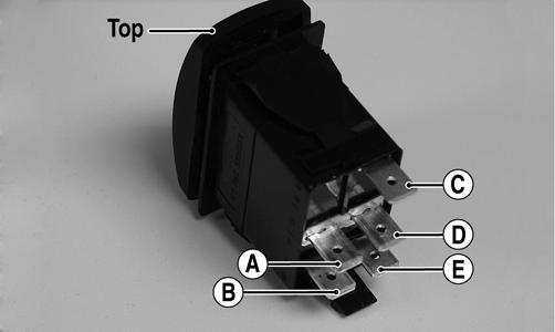
PR566A WIRE COLOR 2WD 4WD DIFFERENTIAL LOCK
Black to Orange12.0 DC Volts12.0 DC Volts 12.0 DC Volts Black to White/ 11.5 DC Volts 0 DC Volts 0 DC Volts
Green Black to White/ 11.5 DC Volts11.5 DC Volts 0 DC Volts Red
2WD 4WD DIFFERENTIAL LOCK
A to D <1 ohm A to D <1 ohm A to D <1 ohm C to E <1 ohm C to E <1 ohm C to E <1 ohm A to B Open A to B <1 ohm A to B <1 ohm A to C Open A to C Open A to C <1 ohm A to E Open A to B <1 ohm A to C <1 ohm
VOLTAGE
NOTE: Voltage tests must be made with the
switch and the actuator connected. The meter can be connected at the actuator connector using a break-out harness or MaxiClips.
2.Select the DC Volts position on the tester and observe the meter readings for each of the three switch positions.
NOTE: If the meter does not show voltages accord-
ing to the chart, make sure the front drive actuator is plugged in; then troubleshoot the switch, ignition fuses, battery connections, or wiring harness.
Reverse Override Switch
VOLTAGE
NOTE: To perform the following tests, the ignition
switch must be in the ON position and the transmission shifted into reverse gear.
1.Connect the red meter lead to the black/blue wire and the black meter lead to a suitable ground; then select 2WD on the drive select switch. The meter must show approximately 1.5 DC volts. 2.Depress the reverse override switch. The meter showing should not change from step 1. 3.Select 4WD on the drive select switch. The meter must show approximately 5 DC volts. 4.Depress the reverse override switch. The meter must show approximately 1.5 DC volts. 5.Connect the red meter lead to the red/yellow wire.
The meter must show approximately 1.5 DC volts.
Depress the reverse override switch. The meter must show approximately 1.5 DC volts. 6.Connect the red meter lead to the red/green wire. The meter should show 0 DC volts.
7.Depress the reverse override switch. The meter must show approximately 5 DC volts.
Front Drive Actuator
NOTE: With the engine stopped and the ignition
switch in the ON position, a momentary “whirring” sound must be noticeable each time the drive select switch is moved to 2WD and 4WD. Test the switch, 30 amp fuse, and wiring connections prior to testing the actuator.
NOTE: The differential must be in the unlocked
position for this procedure.
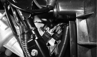
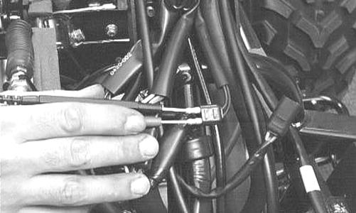
1.Locate the 4-wire connector for the front drive selector actuator on the frame to the right of the differential; then connect the red meter lead to the orange wire using a MaxiClip.
PR293
2. Connect the black lead to the black wire using a Maxi-
Clip; then select 2WD on the drive select switch.
PR295
NOTE: The black tester lead can remain con-
nected to the black wire for the remaining tests.
3.Turn the ignition switch to the ON position. The meter must show battery voltage. NOTE: If battery voltage is not shown, trouble-
shoot the 10 amp ignition (IGN) fuse on the power distribution module, the ignition switch, or the main wiring harness.
4.Connect the red meter lead to the white/red wire. The meter must show battery voltage. 5.Select 4WD on the drive select switch. The meter must show 0 DC volts.
6.Connect the red meter lead to the white/orange wire.
The meter must show battery voltage. 7.Engage the differential lock. The meter must show 0
DC volts.
NOTE: If the meter does not show 0 DC volts,
rock the vehicle to help engage the differential lock; then troubleshoot the differential lock switch (see Drive Select Switch in this section).
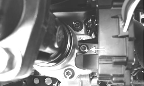
Stator Coil/Crankshaft Position (CKP) Sensor
VOLTAGE (AC Generator - Regulated Output) 1.Set the meter selector to the DC Voltage position. 2.Connect the red tester lead to the positive battery post; then connect the black tester lead to the negative battery post. 3.With the engine running at a constant 5000 RPM (with the headlights on), the meter must show 1415.5 DC volts.
CAUTION
Do not run the engine at high RPM for more than 10 seconds.
NOTE: If voltage is lower than specified, test AC
Generator - No Load.
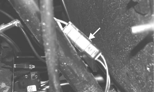
VOLTAGE (AC Generator No Load)
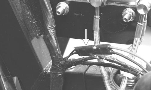
The connector is the black three-pin one on the left side above the shift lever.
FI083B
NOTE: Test the connector coming from the
engine.
1.Set the meter selector to the AC Voltage position. 2.Test between the three yellow wires for a total of three tests.
3.With the engine running at a constant 5000 RPM, all wire tests must be within specification.
CAUTION
Do not run the engine at high RPM for more than 10 seconds.
NOTE: If both stator coil tests failed, check all
connections, etc., and test again. If no voltage is present, replace the stator coil assembly.
CAUTION
Always disconnect the battery when performing resistance tests to avoid damaging the multimeter.
1.Set the meter selector to OHMS position. 2.Test between the three yellow wires for a total of three tests.
3.The meter reading must be within specification. RESISTANCE (Crankshaft Position Sensor)
1.Set the meter selector to the OHMS position. 2.Connect the red tester lead to the blue wire; then connect the black tester lead to the green wire. The meter reading must be within specification. AC VOLTAGE
NOTE: The battery must be at full charge for
these tests.
Crankshaft Position Sensor
1.Set the meter selector to the AC Voltage position. 2.Connect the red tester lead to the blue wire; then connect the black tester lead to the green wire. 3.Crank the engine over using the electric starter. 4.The meter reading must be within specification.
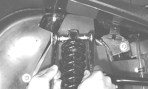
Starter Motor
NOTE: The starter motor is not a serviceable
component. If the starter is defective, it must be replaced.
REMOVING
1.Disconnect the battery.
2.Remove the nut securing the positive cable to the starter; then remove the cable from the starter. 3.Remove the two cap screws securing the starter with ground wires to the crankcase; then remove the starter. Account for the wiring forms and an O-ring. INSTALLING
1.Apply a small amount of grease to the O-ring seal on the starter; then install the starter into the crankcase.
Secure with two machine screws and wiring forms. 2.Secure the positive cable to the starter with the nut.
CAUTION
Always disconnect the negative battery cable from the battery first; then disconnect the positive cable.
Perform this test on the starter positive terminal. To access the terminal, slide the boot away. NOTE: The ignition switch must be in the ON posi-
tion, and the shift lever in the NEUTRAL position.
1.Set the meter selector to the DC Voltage position. 2.Connect the red tester lead to the starter terminal; then connect the black tester lead to ground. 3.With the starter button depressed, the meter must show battery voltage and the starter should operate.
AR607D
NOTE: If the meter showed battery voltage but
the starter did not operate or operated slowly, inspect battery voltage (at the battery), starter condition, and/or ground connections.
NOTE: If the meter showed no battery voltage,
inspect the main fuse, ground connections, starter lead, battery voltage (at the battery), starter relay, or the neutral start relay.
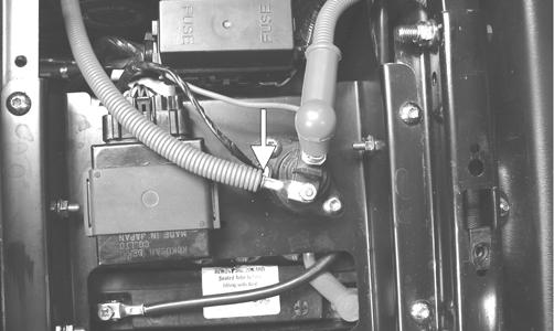
Starter Relay
1.Remove the seat base and battery cover; then using the multimeter set to the DC Voltage position, check the relay as follows. 2.Connect the red tester lead to the positive battery terminal; then connect the black tester lead to the starter cable connection on the starter relay. The meter must show battery voltage.
PR296
NOTE: Make sure the ignition switch is in the ON
position, transmission in neutral, and parking brake set.
3.Depress the starter button while observing the multimeter. The multimeter should drop to 0 volts and a
“click” should be heard from the relay. NOTE: If a “click” is heard and more than one volt
is indicated by the multimeter, replace the starter relay. If no “click” is heard and the multimeter continues to indicate battery voltage, proceed to step 4.
4.Disconnect the two-wire plug from the starter relay; then connect the red tester lead to the green wire and the black tester lead to the black wire.
PR297A
5.Depress the starter button and observe the multimeter. NOTE: If battery voltage is indicated, replace the
starter relay.
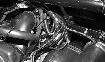
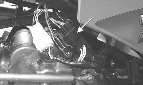
Electronic Control Unit (ECU)
The ECU is located beneath the seat near the battery. NOTE: The ECU is not a serviceable component.
If the unit is defective, it must be replaced.
The ECU is rarely the cause for electrical problems; however, if the ECU is suspected, substitute another ECU to verify the suspected one is defective. This EFI system has a built-in feature that will only allow an ECU of the same part number to be used in this model. Do not attempt to substitute an ECU from a different model as the system will not allow it to start. Error codes can be cleared by following the procedures located in the ECU Error Codes sub-section in this section.
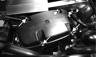
Regulator/Rectifier
The regulator/rectifier is located under the seat next to the battery. Try to verify all other charging system components before the regulator/rectifier is replaced. TESTING VOLTAGE
1.Start engine and warm up to normal operating temperatures; then connect a multimeter (set at the DC
Voltage position) to the battery as follows. 2.Connect the red tester lead to the positive battery post and the black tester lead to the negative battery post. 3.Slowly increase RPM. The voltage should increase with the engine RPM to a maximum of 15.5 DC volts. NOTE: If voltage rises above 15.5 DC volts, the reg-
ulator is faulty or a battery connection is loose or corroded. Clean and tighten battery connections or replace the regulator/rectifier. If voltage does not rise, replace the regulator/rectifier.
Headlights
The connectors are the four 2-prong ones secured to the headlight bulbs (two on each side). VOLTAGE
NOTE: The low beams are the outside bulbs
(black and white wires) and the high beams are the inside bulbs (yellow and black wires). Always connect the black tester lead to the black wires. The ignition switch must be in the ON position.
1.Set the meter selector to the DC Voltage position. 2.Set the light switch to the correct position for the affected light; then connect the black tester lead to the black wire using a MaxiClip. 3.Connect the red tester lead to the yellow wire (high beam) or white wire (low beam) using a MaxiClip.
The meter must show battery voltage. NOTE: If battery voltage is not shown in any test,
inspect the LIGHTS fuse on the power distribution module, headlight switch, ignition switch, switch connectors, or wiring harness.
Taillight-Brakelight
VOLTAGE (Taillight) NOTE: Perform this test at the socket end of the
taillight-brakelight harness (pigtail). The ignition switch must be in the ON position and either high beam or low beam selected on the light switch.
1.Set the meter selector to the DC Voltage position. 2.Connect the black tester lead to the black wire; then connect the red tester lead to the white wire. The meter should show battery voltage. 3.With the ignition key in the LIGHTS position, the meter must show battery voltage. NOTE: If battery voltage is not shown and the
headlights are illuminated, inspect the three-wire connector in the left-rear canopy tube at the juncture of the canopy tube and lower frame. If battery voltage is shown on the meter, replace the bulb.
VOLTAGE (Brakelight) NOTE: Perform this test at the socket end of the
taillight-brakelight harness (pigtail). The ignition switch must be in the ON position.
1.Set the meter selector to the DC Voltage position. 2.Connect the red tester lead to the red/blue wire; then connect the black tester lead to the black wire.
3.With the brake applied, the meter must show battery voltage. NOTE: If the meter shows no voltage, inspect the
10 amp ignition (IGN) fuse, brakelight switch, wiring harness, or connectors.
Ignition Timing
The ignition timing cannot be adjusted; however, verifying ignition timing can aid in troubleshooting other components. To verify ignition timing, use the following procedure. NOTE: To check ignition timing, the seat, seat
back, and seat base must be removed.
1.Attach the Timing Light to the spark plug high tension lead; then remove the timing inspection plug from the left-side crankcase cover.
2.Start the engine and using the RPM function on the speedometer/tachometer, run at 1500 RPM; ignition timing should be 10° BTDC. 3.Install the timing inspection plug. If ignition timing cannot be verified, the rotor may be damaged, the key may be sheared, the trigger coil bracket may be bent or damaged, or the ECU may be faulty.
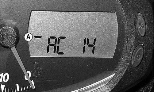
ECU Error Codes
If a sensor fails or an out-of-tolerance signal is sensed by the ECU, an error code will be generated by the ECU. The EFI icon will flash and the gauge will go blank for 30 seconds.
To read the error code(s), use the following procedure. 1.Make sure the ignition switch is in the OFF position; then remove the seats.
2.Locate the diagnostic plug next to the PDM; then remove the black rubber cap. 3.Connect the Test Plug from Test Plug/Code List to the diagnostic plug.
ATV-112
4.Turn the ignition switch to the ON position and read the error code on the LCD. Refer to the following ECU
Error Code List to identify the specific problem area. ECU Error Code List
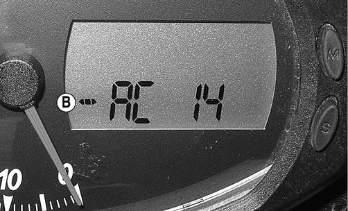
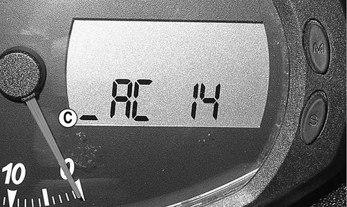
NOTE: Each of the following numerical codes will have a two-letter prefix. A prefix of AC (Active Code) or SC (Stored Code) will be displayed. Always correct and clear Active Codes before clearing Stored Codes.
•00 =No Fault Detected (active code only) •12 =CKP (Crankshaft Position) Sensor* •13 =APS (Air Pressure Sensor) •14 =TPS (Throttle Position Sensor) •15 =ECT (Engine Coolant Temperature) Sensor •16 =Speed Sensor •21 =IAT (Inlet Air Temperature) Sensor •23 =Tilt Sensor* •24 =Ignition Coil #1* •32 =Fuel Injector #1* •40 =ISC (Idle Speed Control) Valve •41 =Fuel Pump Relay* •60 =Cooling Fan Relay •95 =Sensor Power •96 =Incorrect ECU* •97 =ECU Memory Power (constant battery power)
*Will initiate code 99. After all stored codes are cleared, clear the error code(s) using the following procedure. NOTE: The ignition switch should be in the OFF
position.
1.With the test plug connected to the diagnostic plug and the drive select switch in the 4WD position, hold the reverse override switch down and turn the ignition switch to the ON position. 2.After ten seconds, release the reverse override switch and turn the ignition switch to the OFF position; then turn the ignition switch to the ON position. The display should read AC00 (no fault detected). NOTE: If the LCD still displays an error code,
continue troubleshooting the appropriate component.
3.Disconnect the test plug; then install the black rubber cap.
Tilt Sensor
! WARNING
Incorrect installation of the tilt sensor could cause sudden loss of engine power which could result in loss of vehicle control resulting in injury or death.
CAUTION
Do not drop the tilt sensor as shock can damage the internal mechanism.
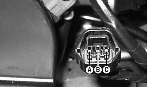
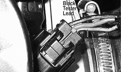
SUPPLY VOLTAGE
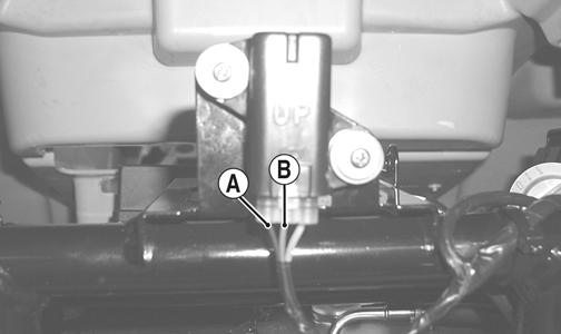
1.Disconnect the three-wire connector from the sensor; then select DC Voltage on the multimeter and connect the red tester lead to the orange wire (C) and the black tester lead to the black wire (A).

CD706A
2.Turn the ignition switch to the ON position. The multimeter should read battery voltage. If battery voltage is not indicated, check the 30-amp fuse, wiring harness, or the ignition switch.
3.Remove the red tester lead and connect to the blue/ brown wire (B). The multimeter should read approximately 2.5 DC volts. If the specified voltage is not indicated, check wire connections at the ECU or substitute another ECU to verify the test. REMARQUE: Do not attempt to substitute an ECU
from a different model as the system will not allow it to start.

CD706B
OUTPUT VOLTAGE
NOTE: Needle adapters will be required on the
multimeter leads as the following tests are made with the sensor connected.
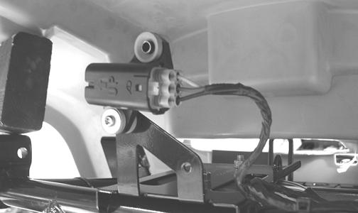
1.Connect the three-wire plug to the sensor; then remove the right-side mounting screw securing the sensor to the rear frame.
CD707
2.Install the needle adapters to the multimeter leads; then select DC Voltage on the multimeter. 3.Connect the red tester lead to the blue/brown wire (B) and the black tester lead to the black/yellow wire (A); then turn the ignition switch ON and observe the meter. The meter should read 0.8-3.0 DC volts.
CD705B
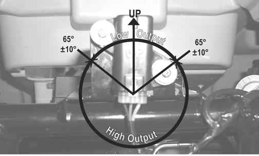
4.Tilt the sensor 60° or more to the left and right observing the meter. The meter should read 4.0-8.0
DC volts after approximately one second in the tilted position. If the meter readings are not as specified, the tilt sensor is defective.
CD709
NOTE: When replacing the sensor after testing,
make sure the arrow marking is directed up.
CD705A
Throttle Position Sensor (TPS)
INSPECTING
1.Remove the seat, seat base, and seat back; then disconnect the three-wire TPS connector plug.
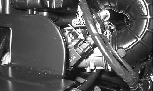
PR533A
NOTE: Prior to testing the TPS, inspect the three-
wire plug connector on the main harness and the three-pin plug on the TPS for contamination, broken pins, and/or corrosion.
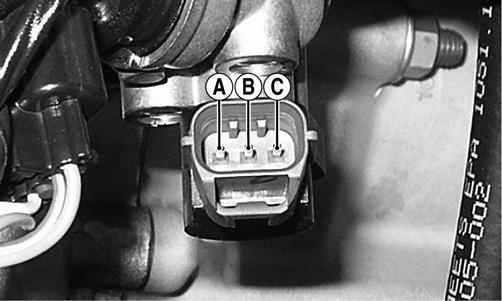
2.Make sure the ignition switch is in the OFF position; then select the DC Voltage position on the meter. 3.Connect the black tester lead to terminal A and the red tester lead to terminal B. Turn the ignition switch to the ON position. The meter should read 4.5-5.5
DC volts.
PR538A
4.Remove the black tester lead from terminal A and connect it to terminal C. The meter should read 5.0
DC volts.
NOTE: If the meter does not read as specified,
check for poor connections at the ECU or open/ broken wires in the wiring harness.
CAUTION
Always make sure the ignition switch is in the OFF position before disconnecting the ECU.
5.Turn the ignition switch to the OFF position. 6.Select the OHMS position on the meter; then perform the following resistance tests on the TPS.
Throttle Position Pins Ohms
Closed A, B, or C to Ground Infinity (Open) A to B 5.0k A to C 650 B to C 4.5k
Full-Open A, B, or C to Ground Infinity (Open) A to C 3.8k B to C 1.3k
PR535A
NOTE: If any meter reading is not as specified,
replace or adjust the TPS (see INSTALLING/ ADJUSTING in this sub-section).
7.Connect the main harness TPS connector to the TPS; then using MaxiClips, connect the black tester lead to the black wire and the red tester lead to the green/ black wire.
PR546A
8.Select the DC Voltage position on the meter and turn the ignition switch to the ON position. The meter should read approximately 0.6 DC volts with the throttle closed and approximately 5.0 DC volts with the throttle in the full-open position. NOTE: If the meter readings are as specified, check
the main harness connector at the ECU main harness wiring. If the meter readings are not as specified, replace the TPS and adjust to specifications (see INSTALLING/ADJUSTING in this sub-section).
CAUTION
Always make sure the ignition switch is in the OFF position before disconnecting the ECU.
9.Clear all ECU error codes after servicing is complete (see ECU Error Codes in this section). REMOVING
1.Remove the seats and center console; then disconnect the three-wire TPS connector plug.
PR533A
2.Remove the screw securing the TPS to the throttle body and remove the TPS. INSTALLING/ADJUSTING
1.Place the TPS into position on the throttle body and secure with the screw. Do not tighten at this time. 2.Connect the main harness to the TPS.
3.Locate the diagnostic plug under the seat next to the
PDM; then install the Test Plug from Test Plug/Error
Code List onto the plug. 4.Turn the ignition switch to the ON position and note the position of the TPS indicator icon (A, B, or C); then adjust the TPS until the TPS icon appears in the center position (B).
PR542A
PR540A
PR541A
5.Tighten the mounting screws securely; then verify the TPS icon appears in the center position. 6.Cycle the accelerator pedal to approximately half throttle six times; then return the accelerator pedal to idle. The display should return to the center position (B). 7.Remove the test plug; then install the seat base, seat back, and seat.
Troubleshooting
Problem: Spark absent or weak Condition Remedy
1. Ignition coil defective 1.Replace ignition coil 2. Spark plug defective 2.Replace plug 3. CKP sensor defective 3.Replace stator assembly 4. ECU defective 4.Replace ECU
Problem: Spark plug fouled with carbon Condition Remedy
1. Gasoline incorrect 1.Change to correct gasoline 2. Air cleaner element dirty 2.Clean element 3. Spark plug incorrect (too cold) 3.Replace plug 4. Valve seals cracked - missing 4.Replace seals 5. Oil rings worn - broken 5.Replace rings
Problem: Spark plug electrodes overheat or burn Condition Remedy
1. Spark plug incorrect (too hot) 1.Replace plug 2. Engine overheats 2.Service cooling system 3. Spark plug loose 3.Tighten plug
Problem: Battery does not charge Condition Remedy
1. Stator wires/connections shorted - loose - open 1.Repair - replace - tighten wires 2. Stator coils shorted - grounded - open 2.Replace stator coils 3. Regulator/rectifier shorted - punctured 3.Replace regulator/rectifier
Problem: Battery charges, but charging rate is below the specification Condition Remedy
1. Stator wires shorted - open - loose (at terminals) 1.Repair - tighten wires 2. Stator coils grounded - open 2.Replace stator coils 3. Regulator/rectifier defective 3.Replace regulator/rectifier 4. Electrolyte low 4.Add distilled water 5. Cell plates (battery) defective 5.Replace battery
Problem: Magneto overcharges Condition Remedy
1. Internal battery short circuited 1.Replace battery 2. Regulator/rectifier resistor damaged - defective 2.Replace resistor 3. Regulator/rectifier poorly grounded 3.Clean - tighten ground connection
Problem: Charging unstable Condition Remedy
1. Stator wire intermittently shorting 1.Replace stator wire 2. Magneto internally shorted 2.Replace stator assembly 3. Regulator/rectifier defective 3.Replace regulator/rectifier
Problem: Starter does not engage Condition Remedy
1. Battery charge low 1.Recharge - replace battery 2. Switch contacts defective 2.Replace switch 3. Starter brushes not seating 3.Replace starter 4. Starter relay defective 4.Replace relay 5. Transmission in gear/park 5.Depress brake/shift to neutral 6. Wiring connections loose - disconnected 6.Connect - tighten - repair connections
Problem: Battery “sulfation” (Acidic white powdery substance or spots on surfaces of cell plates) Condition Remedy
1. Charging rate too low - too high 1.Replace battery 2. Battery electrolyte excessive - insufficient 2.Keep electrolyte to prescribed level 3. Specific gravity too high - too low 3.Charge battery - add distilled water 4. Battery run-down - damaged 4.Replace battery 5. Electrolyte contaminated 5.Replace battery
Problem: Battery discharges too rapidly Condition Remedy
1. Electrolyte contaminated 1.Replace battery 2. Specific gravity too high 2.Charge battery - add distilled water 3. Charging system (charging operation) not set properly 3.Check AC generator - regulator/rectifier - circuit connections 4. Cell plates overcharged - damaged 4.Replace battery - correct charging system 5. Battery short-circuited 5.Replace battery 6. Specific gravity too low 6.Recharge battery
Problem: Battery polarity reversed Condition Remedy
1. Battery incorrectly connected 1.Reverse connections - replace battery