2 minute read
Circuit Wiring Repair


Installing the Right Handlebar Switches
Install the switches (start, engine stop, turn signal and brake light) in the respective housing sockets and install the retaining brackets, using a Phillips screwdriver. Then secure the harness to the housing. Apply a small amount of blue threadlock to the throttle/switch housing mounting screws. Apply a small amount of grease to the cable ferrules and install the ferrules on the cable ends.
Advertisement
Slide the ferrules into the throttle rotator ring and make sure the rotator ring is seated correctly in the lower throttle housing section. Carefully place the top throttle housing section onto the bottom section. Install the two mounting screws and tighten very lightly. Rotate the throttle, checking for smooth operation. Align the throttle switch housing so that the parting line is parallel with the ground. Tighten the two housing mounting screws, using a 5/32” hex bit.
Again, check for proper throttle rotation. Apply blue threadlock to the two master cylinder and brake lever assembly clamp screws. Position the brake assembly to the handlebar; install the clamp and two screws. DO NOT tighten the clamp screws at this time. Pull the brake lever to the handlebar and slide the brake assembly into the throttle/switch housing.
Failure to pull the lever before sliding can damage the brake light switch.
Release the brake lever. Then, tighten the two brake assembly clamp screws, using a 5/32” hex bit.
Installing the Left Handlebar Switches
Install the switches (headlight, horn and turn signal) in the respective housing sockets and install the retaining brackets, using a Phillips screwdriver. Then, secure the harness to the housing. Apply a small amount of blue threadlock to the switch housing mounting screws. Carefully place the top housing section onto the bottom section. Install the two mounting screws and tighten very lightly. Align the switch housing so that the parting line is parallel with the ground and tighten the two mounting screws, using a 5/32” hex bit. Apply blue threadlock to the two clutch lever assembly clamp screws. Position the assembly to the handlebar; install the clamp and two screws and securely tighten.
Completing the Installation
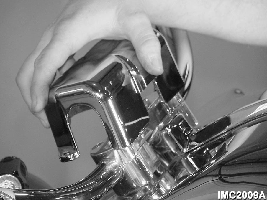
Position the handlebar clamp cover over the handlebar. Install the cover screws and tighten, using a 3/16” hex bit.
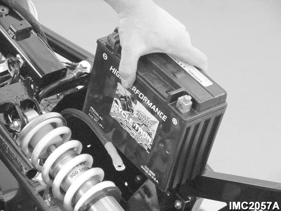
Place the dash panel in position over the fuel tanks and secure the panel with the socket head screws in the instrument bezel and at the rear of the panel. Tighten the screws to specification, using a 5/32” hex bit. Reconnect the battery positive cable and then the negative cable to the battery terminals. Refer to the procedure under Battery and Cables in the CHARGING SYSTEM SERVICE section.
Place the seat in position on the frame and install the two screws to attach the seat to the frame, using a 3/16” hex bit. Tighten the screws to specification.
Whenever repairing or replacing a wire in a circuit, it is important that the connections are secure, properly insulated and sealed to prevent corrosion. When replacing a circuit wire, be sure that the replacement wire is of the same type and gauge. Use only rosin core solder for the spliced connections; never acid core solder. Acid core solder IS NOT intended for electrical circuits and will readily corrode in the electrical environment.
Whenever any tie straps used to secure circuit wires and/or harnesses are removed to make repairs, it is important that they be replaced. Wires and harnesses must be routed and secured in a position where they are protected from moving parts or other objects.