6 minute read
000 Through 17,000 lb. Capacity Single Speed .. 4-1 Differential Case and Drive Pinion (Eaton) 18,500


Fig. 19G~Ring Gear Thrust Pad Adjustment
NOTE: Make sure screw does not turn during locking process. This adjustment provides .005" to .007' clearance between thrust pad and ring gear face.
In s ta lla tio n
1. Clean out axle housing and cover and place new gasket over axle housing. 2. Assemble differential carrier to axle housing, install lockwashers and bolts and tighten securely. 3. Replace axle housing inspection cover, if removed, using new gasket.
NOTE: This propeller shaft to pinion flange fastener is an important attaching part in that it could affect the performance of vital components and systems, and/or could result in major repair expense. It must be replaced with one of the same part number or with an equivalent part if replacement becomes necessary. Do not use a replacement part of lesser quality or substitute design. Torque values must be used as specified during reassembly to assure proper retention of this part.
4. Assemble rear universal joint. 5. Install axle shafts as outlined in applicable axle installation procedure in Service Manual. 6. Fill axle with lubricant to a level even with bottom of filler hole. See Section 0 Service Manual for proper lubricant.
1 5 ,0 0 0 AND 1 7 ,0 0 0 LB. CAPACITY TWO-SPEED
INDEX

Differential Carrier Assembly .................................... 4.9 Removal...................................................................... 4.9 Disassembly................................................................ 4 4 2 Repairs........................................... ............................. 4.13 Drive Pinion and Bearing R etainer.................. 4.13 Disassembly....................................................... 4.13 Inspection............................................................ 4-14 Reassembly.......................................................... 4-14 Differential and P la n e t........................................ 4-15
Disassembly...........................................................4-15 Inspection................................................................4-16 Reassembly..............................................................4-17 Reassembly ................................................................4-17 Ring Gear and Pinion Adjustment....................4-18 Checking Pinion D epth........................................4-19 Shifting Yoke, Sleeve and Shaft Installation 4-19 Installation..................................................................4-19
DIFFERENTIAL CARRIER ASSEMBLY
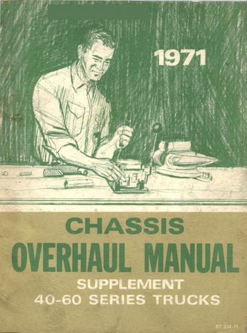
Removal
1. Loosen the lower carrier-to housing attaching cap screws and drain lub' icant from housing. 2. Remove axle shafts and electric or vacuum lines as outlined in Truck Service Manual. 3. Remove propeller shaft from pinion flange. Tape bearing caps to keep them in place. Swing the propeller shaft to one side and tie it to the frame side rail. 4. Remove all differential carrier-to-axle housing cap screws and lock washers exept two near top of carrier.
Loosen the two cap screws at the top, but leave installed to prevent carrier from falling. 5. Tap along the outer perimeter of the carrier with a soft-faced hammer to break bond between carrier and housing. 6. Support carrier with a roller jack, then remove the remaining cap screws and lock washers. Work the assembly forward until it clears the housing. A small, round pry bar or a long drift may be inserted in one of the upper holes to keep carrier aligned with housing.
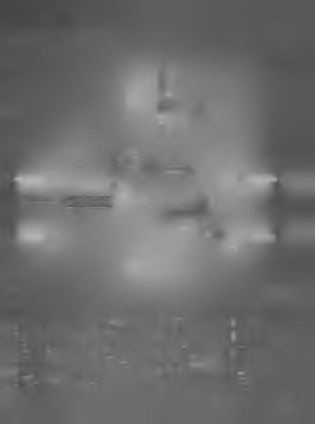
Fig. 1 J--Two-Speed Axle Cross Section

1. Pinion Flange 2. Dust Deflector 10. Pinion Rear Bearing 1 1. Differential and 18. Thrust Washers 19. Differential and
3. Pinion Oil Seal
Planet Support Planet Support Case 4. Pinion Front Bearing 12. Differential Bearing 5. Pinion Adjusting (Right) Cover 20. Axle Housing Cover
Shim 6. Pinion Bearing 13. Axle Shaft 14. Axle Housing (Welded) 21. Differential Pinion
Preload Spacer 7. Pinion Intermediate
Bearing 15 Differential Bearing 22. Filler Plug
Adjusting Nut (Right)
23. Differential Pinion 16. Oil Baffle Shaft
8. Pinion 9. Differential Carrier 17. Adjusting Nut Lock
24. Differential Side Gear (Right) (Left) 25. Magnetic Chip Collector 26. Planet Gears (4) 27. Differential and Planet Support Case 28. Shift Yoke 29. Shift Sleeve 30. Anchor Bolt Lock 31. Anchor 32. Sun Gear 33. Ring Gear 34. Pinion and Bearing Retainer
14 15


Fig. 2J--Exploded View of Carrier 1. Pinion Retaining Nut 8. Pinion Interm ediate 16. Differential Bearing 21. Differential Baring 26. Differential Pinion 31. Sun Gear and W asher Bearing Adjusting Nut and Oil Cap (Left) Shaft 32. Differential and Plane 2 Pinion Flange and 9. Pinion Baffle 22. Differential and 27. Differential Pinion Support Case
Dust Deflector
10. Pinion Rear Bearing 17. Differential Bearing 3. Pinion Oil Seal 1 1. Shift Unit (Vacuum) (Right) 4. Pinion Front Bearing 12. Shift Unit M ounting 18. Ring Gear Planet Support Case and Thrust W asher 33. Differential Bearing Cover 23. Thrust W asher (4) (Left) 28. Differential Side Gear 34. Differential Bearing
5 Pinion and Bearing Bracket 19. Differential Bearing 24. Differential and (2) Adjusting Nut (Left)
Retainer 13. Shifter Yoke Lever Cap (Right) Planet Support Cover 29. Differential and 35. Shift Sleeve 6. Pinion Adjusting 14. Differential Carrier 20. Adjusting Nut Lock 25. Adjusting Nut Lock Planet Support 36. Shift Yoke
Shim 15. Oil Trough (Right) (Left) 30. Planet Gears (4) 37. Shift Anchor 7. Pinion Bearing
Preload Spacer 38. Anchor Bolt Lock
REAR. AXLE DIFFERENTIAL CARRIER 4-11
Fig. 3J~Removing Drive Pinion Nut (Typical)
D isassem bly
(R efer to Figure 2 J for C arrier Components)

1. Place differential carrier assembly in a suitable repair stand or in a large vise with padded jasws and clamp securely to prevent assembly from falling. 2. Using Tool J-3453 to hold flange, remove drive pinion nut and washer (fig. 3J). Discard nut and use a new nut for reassembly. 3. Remove flange from pinion by tapping on flange with a brass drift and hammer. 4. Remove cap screws securing pinion bearing retainer to carrier. Rap retainer sharply with a soft-faced hammer to loosen retainer from carrier. If required a blunt chisel may be used between the carrier and retainer to separate them. 5. Withdraw retainer and pinion from carrier and remove shim(s) from between carrier and retainer. Save shim(s) to facilitate adjustment during reassembly. 6. Remove the three bolts and lock washers retaining shifter assembly to the carrier and remove the shifter assembly. 7. Bend tang on bolt lock down and remove bolt and bolt lock from shift yoke anchor, then remove anchor from carrier. 8. Drive out shifter yoke shaft, using drift and hammer as shown in Figure 4J. 9. Slide the shifter yoke and sleeve to the left, removing the sleeve and shifter yoke from the end of the sun gear (fig. 5J). 10. Remove differential bearing adjusting nut lock from each nut and remove locks from both sides.
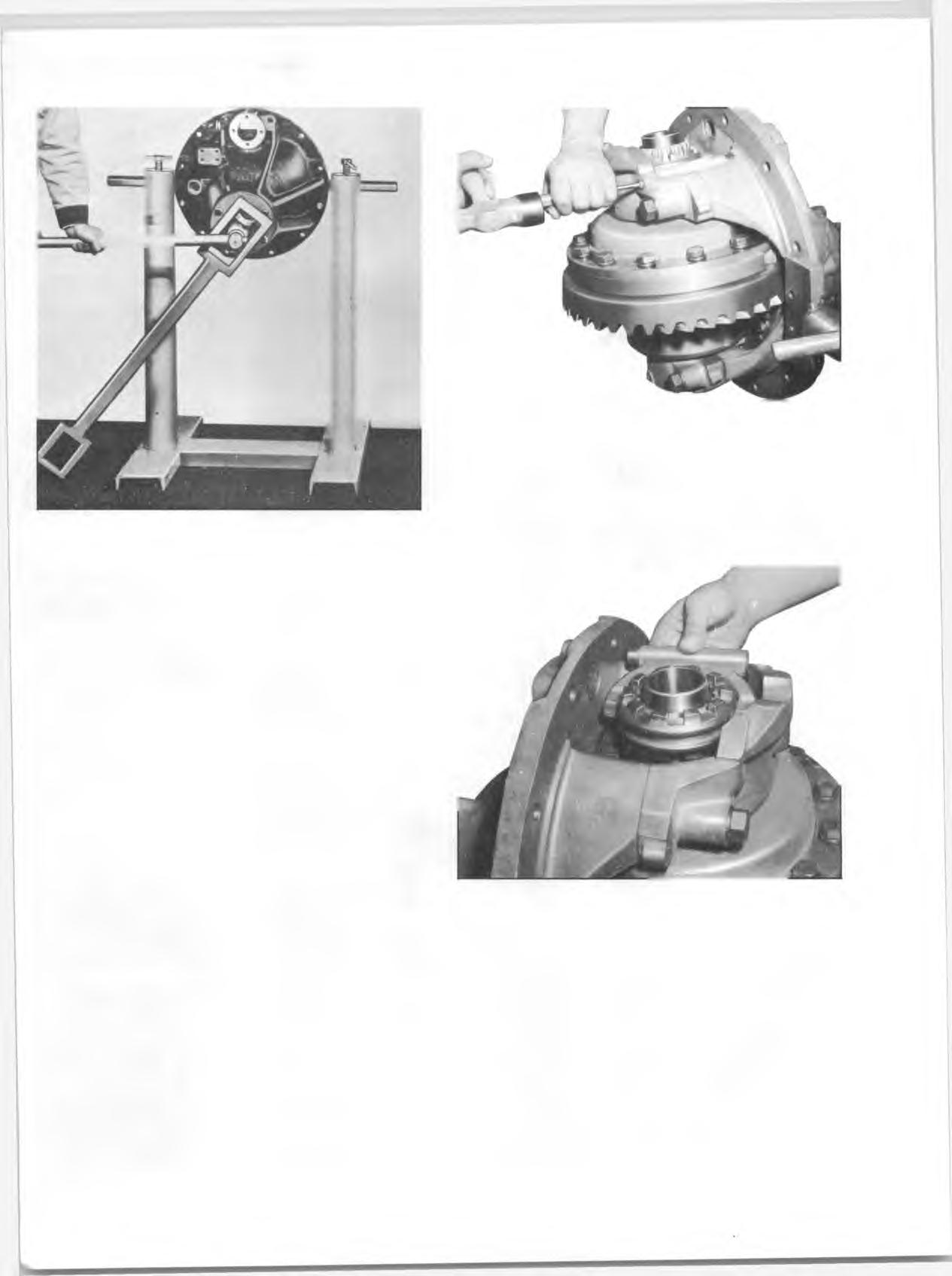
Fig. 4J~Removing Shifter Yoke Shaft
11. Remove the two retaining bolts and withdraw oil trough from the carrier (fig. 6J).
12. Remove bearing caps and adjusting nuts by tapping on bosses of caps until free from dowels (fig. 7J). Remove the differential and planet assembly from the housing.
Fig. 5J--Removing Shifter Yoke and Sleeve
Repairs
D rive Pinion and Bearing R e ta in er Disassembly
1. Pry pinion oil seal from the retainer using care not to damage machined surfaces. 2. Position retainer and pinion assembly in an arbor press with retainer resting on bed of arbor. Press pinion downward and out of retainer (fig. 8J). Remove pinion front bearing inner race from the retainer and remove bearing spacer from pinion-discard spacer. 3. Using 1/2 inch bar stock, cut to a suitable length and positioned in the provided notches, press pinion front and intermediate bearing cups from the retainer (fig. 9J).