2 minute read
Brake Cam Roller Pins (2) .......................... Apply ........................................... . . E 20,000

Sec. 1 Page 27
G ENERAL M A IN T E N A N C E
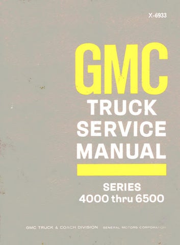
1 Nut 2 Crank Arm 3 Seal Cap 4 Retaining Ring 5 Washer 6 Gear Box Cover 7 Output Gear and
Shaft Assy. 8 Intermediate Gear 9 Wave Washer 10 Gear Box Housing 11 Brush Plate Assy, and Mounting Brackets 12 Brushes 13 Wave Washers
14 Flat Washers 15 Armature 16 Thrust Plug 17 Frame and Field 18 End Plate 19 Tie Bolts (Two Required)
T-3642
Figure 12— W iper Motor a n d Gear Box Asse m bly (Typical)
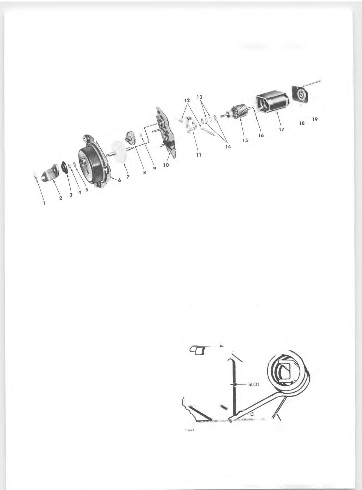
Motor 8. Remove motor through bolts, tap motor frame lightly, and separate motor assembly from gear box housing. 9. Remove brush tension by placing brush spring in holder groove as shown in figure 13. 10. Slide armature and end plate from motor frame and field. Note arrangement of wave washers (fig. 14) on gear end of armature shaft before removing to assure proper installation upon motor assembly. 11. Pull end plate from armature. Note thrust plug between tip of armature shaft and end plate.
INSPECTION
Check armature shaft, gears, and supporting bushings for wear. Inspect commutator for evidence of arcing or loose solder joints to armature windings. Check "PARK" contacts for dirt or oxidation. Inspect for worn brushes, weak springs, and binding in holders.
In general, inspect all parts for serviceability and replace as required. All parts can be replaced individually except motor frame and field which is serviced as an assembly. Service kits provide all necessary attaching parts for installation of gear cover and terminal board.
ASSEMBLY (Fig. 12) Motor
Reassemble motor using reverse order of "Disassembly" procedures.
NOTE: Be sure wave washers on armature shaft are installed properly as shown in figure 14. Lightly lubricate armature shaft bushings with light machine oil. Be sure brushes are properly positioned in holders before armature commutator protrudes between brushes.
Gear Box 1. Assemble gear box in reverse order of "Disassembly" procedures.
NOTE: Lubricate gear teeth with Delco Cam and Ball Bearing Lubricant or equivalent. Be sure cover is properly located over dowel pins and that
B R U SH H O LD ER
REMOVE BRUSH SPRING FROM SLOT A N D PLACE IT IN G R O O V E A S S H O W N
Figure 1 3 — R e le a sin g Brush S p r in g Tension