6 minute read
ELECTRICAL


MACHINE IDENTIFICATION
There are two significant reasons for knowing the serial number of your machine: 1. When ordering parts, you can give the number to your Yamaha dealer for positive identification of the model you own. 2. If your machine is stolen, the authorities will need the number to search for and identify your machine.
VEHICLE IDENTIFICATION NUMBER
The vehicle identification number "1" is stamped on the right of the steering head pipe.
ENGINE SERIAL NUMBER
The engine serial number "1" is stamped into the elevated part of the right-side of the engine.
MODEL LABEL
The model label "1" is affixed to the frame under the rider's seat. This information will be needed to order spare parts.
INCLUDED PARTS VALVE JOINT
This valve joint "1" prevents fuel from flowing out and is installed to the fuel tank breather hose.
In this installation, make sure the arrow faces the fuel tank and also downward. SPARK PLUG WRENCH
This spark plug wrench "1" is used to remove and install the spark plug.
NIPPLE WRENCH
This nipple wrench "1" is used to tighten the spoke.
JET NEEDLE PULL-UP TOOL (Except for Canada)
The jet needle pull-up tool "1" is used to pull the jet needle out of the carburetor.
DRIVE CHAIN SPROCKET GUIDE (For EUROPE)
Use the drive chain sprocket guide "1" when installing the included drive sprockt (13T).
IMPORTANT INFORMATION PREPARATION FOR REMOVAL AND DISASSEMBLY
1. Remove all dirt, mud, dust, and foreign material before removal and disassembly. • When washing the machine with high pressured water, cover the parts follows.
Silencer exhaust port
Side cover air intake port
Water pump housing hole at the bottom
Drain hole on the cylinder head (right side)
All electrical components 2. Use proper tools and cleaning equipment. Refer to "SPECIAL
TOOLS" section. 3. When disassembling the machine, keep mated parts together.
They include gears, cylinders, pistons, and other mated parts that have been "mated" through normal wear. Mated parts must be reused as an assembly or replaced.
4. During the machine disassembly, clean all parts and place them in trays in the order of disassembly.
This will speed up assembly time and help assure that all parts are correctly reinstalled. 5. Keep away from fire.
ALL REPLACEMENT PARTS
1. We recommend to use Yamaha genuine parts for all replacements. Use oil and/or grease recommended by Yamaha for assembly and adjustment.
GASKETS, OIL SEALS AND ORINGS
1. All gaskets, oil seals, and O-rings should be replaced when an engine is overhauled. All gasket surfaces, oil seal lips, and O-rings must be cleaned. 2. Properly oil all mating parts and bearings during reassembly. Apply grease to the oil seal lips.
LOCK WASHERS/PLATES AND COTTER PINS
1. All lock washers/plates "1" and cotter pins must be replaced when they are removed. Lock tab(s) should be bent along the bolt or nut flat(s) after the bolt or nut has been properly tightened.
BEARINGS AND OIL SEALS
1. Install the bearing(s) "1" and oil seal(s) "2" with their manufacturer's marks or numbers facing outward. (In other words, the stamped letters must be on the side exposed to view.) When installing oil seal(s), apply a light coating of lightweight lithium base grease to the seal lip(s). Oil the bearings liberally when installing.
Do not use compressed air to spin the bearings dry. This causes damage to the bearing surfaces. CIRCLIPS
1. All circlips should be inspected carefully before reassembly. Always replace piston pin clips after one use. Replace distorted circlips. When installing a circlip "1", make sure that the sharp-edged corner "2" is positioned opposite to the thrust "3" it receives. See the sectional view.
CHECKING OF CONNECTION
Dealing with stains, rust, moisture, etc. on the connector. 1. Disconnect: • Connector 2. Dry each terminal with an air blower.
3. Connect and disconnect the connector two or three times. 4. Pull the lead to check that it will not come off. 5. If the terminal comes off, bend up the pin "1" and reinsert the termi
nal into the connector. 6. Connect: • Connector
The two connectors "click" together. 7. Check for continuity with a tester.
• If there in no continuity, clean the terminals. • Be sure to perform the steps 1 to 7 listed above when checking the wire harness. • For a field remedy, use a contact revitalizer available on the market. • Use the tester on the connector as shown.
SPECIAL TOOLS
The proper special tools are necessary for complete and accurate tune-up and assembly. Using the correct special tool will help prevent damage caused by the use of improper tools or improvised techniques. The shape and part number used for the special tool differ by country, so two types are provided. Refer to the list provided to avoid errors when placing an order.
• For U.S.A. and Canada, use part number starting with "YM-", "YU-" or "ACC-". • For others, use part number starting with "90890-".
Tool name/Part number Crankcase separating tool YU-1135-A, 90890-01135 How to use These tool is used to remove the crankshaft from either case. Illustration
Dial gauge and stand YU-3097, 90890-01252 Stand YU-1256 These tools are used to check each part for runout or bent.
Crankshaft installing tool Crankshaft installing pot YU-90050, 90890-01274 Crankshaft installing bolt YU-90050, 90890-01275 Spacer (crankshaft installer) YU-91044, 90890-04081 Adapter (M12) YU-90063, 90890-01278
Piston pin puller set YU-1304, 90890-01304
Radiator cap tester YU-24460-01, 90890-01325 Radiator cap tester adapter YU-33984, 90890-01352 These tools are used to install the crankshaft.
This tool is used to remove the piston pin.
These tools are used for checking the cooling system.
Tool name/Part number How to use Illustration Steering nut wrench This tool is used when tighten the YU-33975, 90890-01403 steering ring nut to specification.
Damper rod holder YM-01494, 90890-01494 Use this tool to remove and install the damper rod.
Fork seal driver YM-A0948, 90890-01502 This tool is used when install the fork oil seal.
Spoke nipple wrench YM-01521, 90890-01521
Sheave holder YS-1880-A, 90890-01701 This tool is used to tighten the spoke.
This tool is used for when loosening or tightening the flywheel magneto securing nut.
Pocket tester YU-3112-C, 90890-03112 Use this tool to inspect the coil resistance, output voltage and amperage.
Tool name/Part number How to use Illustration Timing light This tool is necessary for checking YM-33277-A, 90890-03141 ignition timing.
Valve spring compressor YM-4019, 90890-04019
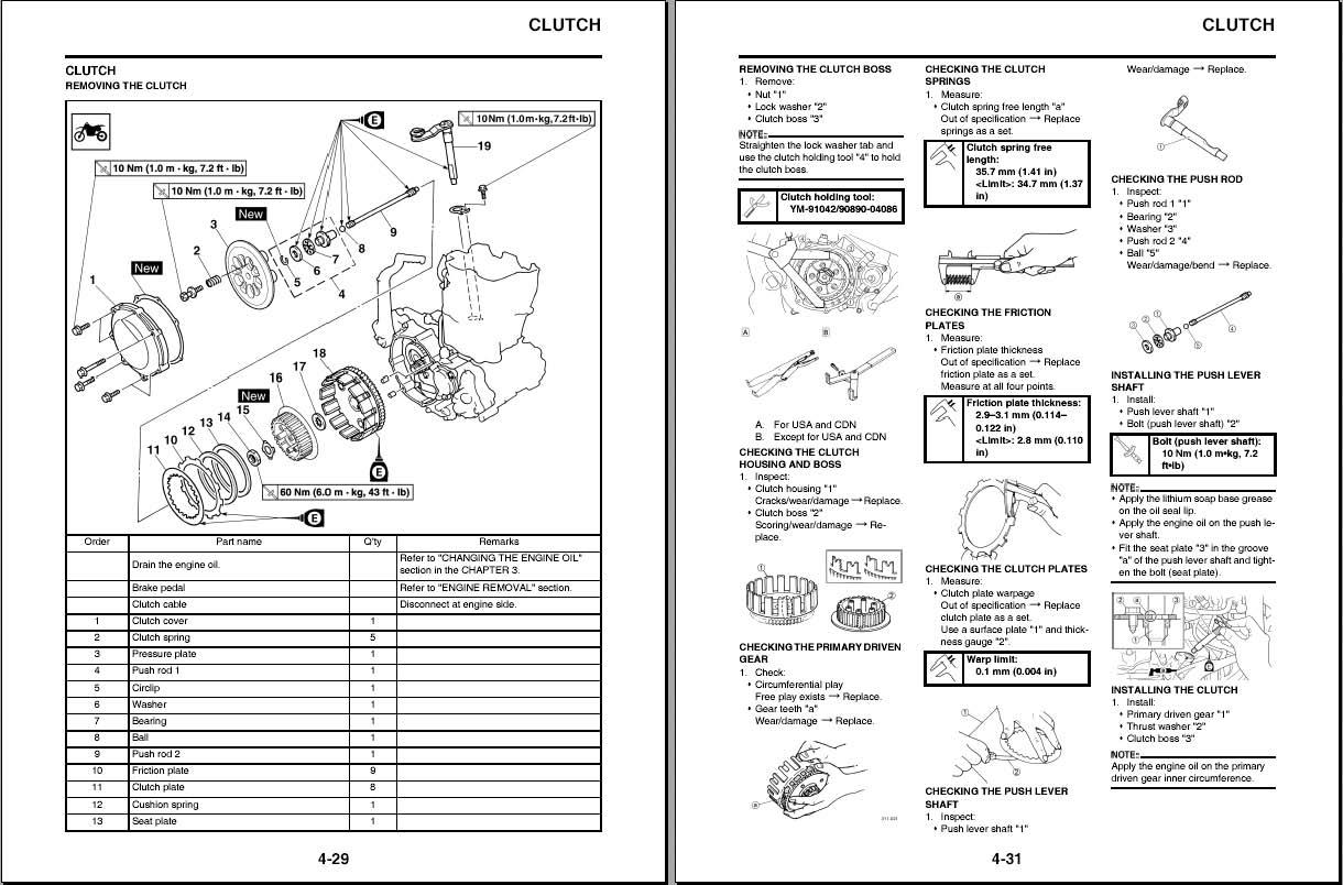
Clutch holding tool YM-91042, 90890-04086 This tool is needed to remove and install the valve assemblies.
This tool is used to hold the clutch when removing or installing the clutch boss securing nut.
Valve guide remover Intake 4.0 mm (0.16 in) Exhaust 4.5 mm (0.18 in) YM-4111, 90890-04111 YM-4116, 90890-04116
Valve guide installer Intake 4.0 mm (0.16 in) Exhaust 4.5 mm (0.18 in) YM-4112, 90890-04112 YM-4117, 90890-04117
Valve guide reamer Intake 4.0 mm (0.16 in) Exhaust 4.5 mm (0.18 in) YM-4113, 90890-04113 YM-4118, 90890-04118
Rotor puller YM-04141, 90890-04141 This tool is needed to remove and install the valve guide.
This tool is needed to install the valve guide.
This tool is needed to rebore the new valve guide.
This tool is used to remove the flywheel magneto.
Tool name/Part number How to use Illustration Dynamic spark tester This instrument is necessary for YM-34487 checking the ignition system compoIgnition checker nents. 90890-06754
Vacuum/pressure pump gauge set YB-35956-A, 90890-06756 This tool is used to check the air induction system.
YAMAHA Bond No. 1215 (ThreeBond ® No. 1215) 90890-85505 This sealant (Bond) is used for crankcase mating surface, etc.
CLICK HERE TO DOWNLOAD THE COMPLETE MANUAL
• Thank you very much for reading the preview of the manual . • You can download the complete manual from: www.heydownloads.com by clicking the link below
• Please note: If there is no response to
CLICKING the link, please download this PDF first and then click on it.
CLICK HERE TO DOWNLOAD THE COMPLETE MANUAL