3 minute read
Part 4 - Getting started
4
PART 4 GETTING STARTED
The diagram is used to engineer an air handling unit. In this example, we will show you how to calculate the following aspects of a unit using the Mollier diagram:
Cooling coil Heater capacity Steam humidifie
We start by establishing the outside and inside conditions. This is our field of operation, which sets the boundaries within which we work.
A common mistake is to set the conditions extremely high. To be ‘on the safe side’. We often get requests for outside conditions like 50°C – 80%RH. Not only are these impossible ambient conditions, it will make the installation unnecessary heavy and more difficult to operate.
For this example, we will assume the following conditions:
Outside: 35 °C – 70% RH Inside: 21 °C – 60% RH
Energy e f ficiency

Every system reduces energy loss by using the heat or cold that are already present and transferring part into the outside air. There are a range of ways to reduce energy, each of which has its pros and cons. In this example, we will use one of the most common methods: a recirculation rate of 50%.
STEP 1 - CALCULATING COIL
The cooling coil we are using is chilled water-fed, with a temperature of 12 °C in and 6 °C out.
1: Marking points in the diagram We start with the easy part, that is putting the fixed points into the diagram. We begin by locating the outside and inside condition and drawing a line between them. (Image 6)
2: Determining the mixing temperature Remember, we are recirculating 50% of the air for energy efficiency purposes. This means the temperature in front of the cooler will be a mix between outside and inside conditions. To calculate the mixing temperature, we use a simple equation:
temp. mix = (temp. outside air amount outside) + (temp. inside air amount inside) ** total air amount
Let us assume a total air amount of 20,000 m³/h. With a recirculation rate of 50%, this gives us 10,000 m³/h for both outside and inside air streams. Now we can calculate the mixing temperature: temp. mix = (35 10,000) + (21 10,000) 20,000 ** This gives us a mixing temperature of 28 °C. (Image 7)

Image 6: Outside and inside coditions

Image 7: Mixing temperature
STEP 1 - CALCULATING COIL
3: Cooling the air The cooler dew point (CDP) is 9 °C and set on the saturation line. You’ll get the CDP by taking the average temperature of the cooling coil, which is 12 °C in and 6 °C out.
To determine the cooler capacity, we follow the lines of constant enthalpy between the mixing temperature and CDP.
This gives us 72 kJ/kg – 27 kJ/kg = 45 kJ/kg. (Image 8)
Image 8: Cooler capacity

STEP 2 - HEATER CAPACITY
The temperature behind the cooler will be around 9 °C. We can round up a degree because of the residual heat of the ventilator, resulting in a temperature of 10°C. Room temperature is 21 °C, giving a temperature differential of 11 °C. (Image 9)
Now we have enough information to calculate the heater capacity using the Q=m*c*ΔT equation. For this example, resulting in a heater capacity of 76kW.
Image 9: Heating the air

STEP 3 - HUMIDIFYING THE AIR
In this example, we use a steam humidifier to bring the air up to a relative humidity of 60%.
Cooling the air extracts a lot of moisture from it. (Image 10)
Now, heating the air brought it to a temperature of 21 °C without changing the absolute humidity. Looking at this line, we see a gap of 2.2 g/kg between our current point and the desired value. (Image 11)
Now we just need to convert the air amount of 20,000 m³/h to kg/s to find out how large the steam humidifier needs to be. For this example, resulting in a humidifier capacity of 15.2 kg.
Image 10: Extracting moisture by cooling
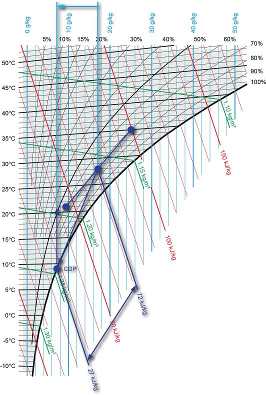

Image 11: Humidifying the air
