SERVICE MANUAL
0116
KEYSHEET
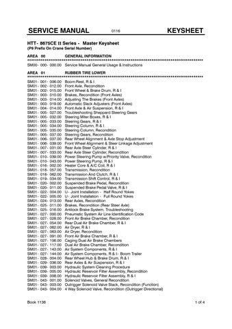
HTT- 8675CE II Series - Master Keysheet (P9 Prefix On Crane Serial Number) AREA 00 GENERAL INFORMATION ******************************************************************************************** SM00- 000- 000.00 Service Manual General Usage & Instructions AREA 01 RUBBER TIRE LOWER ******************************************************************************************** SM01- 001- 006.00 Boom Rest, R & I SM01- 002- 012.00 Front Axle, Recondition SM01- 002- 015.00 Front Wheel & Brake Drum, R & I SM01- 003- 010.00 Brakes, Recondition (Front Axles) SM01- 003- 014.00 Adjusting The Brakes (Front Axles) SM01- 003- 019.00 Automatic Slack Adjusters (Front Axles) SM01- 004- 014.00 Front Axle & Air Suspension, R & I SM01- 005- 027.00 Troubleshooting Sheppard Steering Gears SM01- 005- 032.00 Steering Miter Boxes, R & I SM01- 005- 033.00 Steering Gears, R & I SM01- 005- 034.00 Steering Column, R & I SM01- 005- 035.00 Steering Column, Recondition SM01- 005- 037.00 Steering Gears, Recondition SM01- 006- 037.00 Rear Wheel Alignment & Axle Stop Adjustment SM01- 006- 039.00 Front Wheel Alignment & Steer Linkage Adjustment SM01- 007- 031.00 Rear Axle Steer Cylinder, R & I SM01- 007- 033.00 Rear Axle Steer Cylinder, Recondition SM01- 010- 039.00 Power Steering Pump w/Priority Valve, Recondition SM01- 010- 043.00 Power Steering Pump, R & I SM01- 016- 002.00 Heater Core & A/C Coil, R & I SM01- 018- 057.00 Transmission, Recondition SM01- 018- 062.00 Transmission And Clutch, R & I SM01- 019- 034.00 Transmission Shift Control, R & I SM01- 020- 002.00 Suspended Brake Pedal, Recondition SM01- 020- 011.00 Suspended Brake Pedal Valve, R & I SM01- 022- 004.00 U- Joint Installation - Half Round Yokes SM01- 022- 005.00 U- Joint Installation - Full Round Yokes SM01- 024- 013.00 Rear Axles, Recondition SM01- 025- 011.00 Brakes, Recondition (Rear Steer Axle) SM01- 025- 016.00 Antilock Brake System, Troubleshooting SM01- 027- 000.00 Pneumatic System Air Line Identification Code SM01- 027- 028.00 Front Air Brake Chamber, Recondition SM01- 027- 054.00 Rear Dual Air Brake Chamber, R & I SM01- 027- 062.00 Air Dryer, R & I SM01- 027- 063.00 Air Dryer, Recondition SM01- 027- 091.00 Front Air Brake Chamber, R & I SM01- 027- 106.00 Caging Dual Air Brake Chambers SM01- 027- 117.00 Dual Air Brake Chamber, Recondition SM01- 027- 143.00 Air System Components, R & I SM01- 027- 144.00 Air System Components, R & I - Boom Trailer SM01- 028- 004.00 Rear Wheel Hub & Brake Drum, R & I SM01- 029- 036.00 Rear Axles & Air Suspension, R & I SM01- 039- 003.00 Hydraulic System Cleaning Procedure SM01- 039- 005.00 Hydraulic Reservoir Filter Assembly, Recondition SM01- 039- 008.00 Hydraulic Reservoir Filter Assembly, R & I SM01- 043- 001.00 Solenoid Valves, General Recondition SM01- 043- 003.00 Outrigger Solenoid Valve Stack, Recondition (Function) SM01- 043- 004.00 4 Way Solenoid Valve, Recondition (Outrigger Directional) Book 1138
1 of 4
SERVICE MANUAL SM01- 043- 045.00 SM01- 043- 047.00 SM01- 043- 048.00 SM01- 044- 023.00 SM01- 044- 027.00 SM01- 045- 048.00 SM01- 045- 049.00 SM01- 045- 059.00 SM01- 045- 060.00 SM01- 046- 034.00 SM01- 046- 047.00 SM01- 046- 048.00 SM01- 046- 049.00 SM01- 047- 011.00 SM01- 047- 038.00 SM01- 047- 041.00 SM01- 047- 048.00 SM01- 048- 044.00 SM01- 048- 049.00 SM01- 050- 004.00 SM01- 050- 005.00 SM01- 050- 015.00 SM01- 050- 016.00 SM01- 066- 024.00 SM01- 069- 014.00 SM01- 069- 016.00 SM01- 071- 004.00 SM01- 071- 013.00 SM01- 071- 024.00 SM01- 073- 002.00 SM01- 075- 050.00 SM01- 075- 051.00 SM01- 075- 052.00 SM01- 076- 058.00 SM01- 076- 068.00 SM01- 076- 081.00 SM01- 079- 066.00 SM01- 079- 067.00 SM01- 081- 014.00 SM01- 081- 040.00 SM01- 081- 045.00 SM01- 081- 046.00 SM01- 081- 051.00 SM01- 081- 060.00 SM01- 081- 061.00
0116
KEYSHEET
Outrigger Directional Control Valve, R & I Fifth Outrigger Directional Control Valve, R & I Outrigger Function Control Valve, R & I Fifth Outrigger Lock Valve Cartridge, R & I Outrigger Lock Valve Cartridge, R & I And Recondition (Main Outriggers) Bottom Outrigger Beam Cylinder, Recondition Top Outrigger Beam Cylinder, Recondition Outrigger Beam Assembly, R & I Outrigger Beam Cylinder, R & I Jack Cylinder, Recondition (Fifth Outrigger) Jack Cylinder, R & I (Main Outriggers) Jack Cylinder, Recondition (Main Outriggers) Fifth Outrigger Jack Cylinder, R & I Relief Valve, Recondition (Hydraulic Oil Cooler) Pick & Carry Manifold Block, Illustrated - (G1) Emergency Steering Supply Valve, Recondition Pick & Carry Manifold Block, Illustrated - (G2) Rotating Joint, Recondition Rotating Joint, R & I Hydraulic Oil Cooler Assembly, R & I Oil Cooler Hydraulic Motor, R & I Hydraulic Oil Cooler Accumulator, R & I Oil Cooler Hydraulic Motor, Recondition (Parker) Battery, R & I Tires & Rims, R & I Tire & Rim, Inspection & Maintenance (Aluminum Disc Rims & Tubeless Tires) Repair Of Components Made Of Fibrous Composite Materials Engine Housing, R & I Engine Housing, R & I (G2) Electronic Gauge, Troubleshooting Starter, R & I Alternator, R & I Radiator, Charged Air And Transmission Oil Cooler, R & I Collector Ring, R & I Collector Ring, Recondition (37 Rings) Heavy Duty Collector Ring, Recon. (36 Rings) Lower Hydraulic Components, R & I- Rear Steering Lower Hydraulic Components, R & I- Suction, Pressure, & Return Lines Hydraulic Pump, Recondition (Multiple Section Gear Type) Hydraulic Pump, R & I (Tandem Pump) Radiator Fan Motor, R & I Hydraulic Gear Pump/Motor, Recondition- PGM620 Series (Radiator Fan) Hydraulic Pump, R & I (Outriggers/Pick & Carry 2 or 3 - Section) Hydraulic Vane Pump, R & I (Winches, Radiator Fan, Boom Hoist, Rear Steering) Hydraulic Vane Pump, Recondition (Multiple Section Vane Type)
AREA 03 UPPER REVOLVING FRAME ******************************************************************************************** SM03- 001- 075.00 Upper Revolving Frame & Turntable Bearing, R & I SM03- 010- 025.00 Counterweight Removal Cylinder, Recondition SM03- 010- 038.00 Counterweight Removal Control Valve, R & I SM03- 010- 047.00 Counterweight Removal Cylinder, R & I AREA 04 VERTICAL SHAFTS ******************************************************************************************** SM04- 010- 033.00 Swing Reduction Unit w/Brake, Recondition SM04- 010- 038.00 Swing Reduction Unit & Brake, R & I
2 of 4
HTT - 8675CE II Series
SERVICE MANUAL
0116
KEYSHEET
AREA 05 HORIZONTAL SHAFTS ******************************************************************************************** SM05- 006- 025.00 Winch, Recondition SM05- 006- 026.00 Winch, Troubleshooting SM05- 006- 038.00 Winch Assembly, R & I SM05- 018- 003.00 Winch Roller, Recondition AREA 06 UPPER ENGINE ******************************************************************************************** SM06- 008- 009.00 Throttle Treadle Assembly, R & I SM06- 025- 019.00 Operator s Cab Water Heater, R & I (Without Air Conditioning) SM06- 025- 022.00 A/C Coil And Heater Core, Illustrated SM06- 025- 023.00 Upper Cab A/C Coil & Heater Core, R & I SM06- 025- 026.00 Diesel Coolant Heater, Troubleshooting & Recondition SM06- 025- 028.00 Diesel Coolant Heater, R & I SM06- 025- 030.00 Upper Cab Heater Water Swivel, R & I And Recondition (Rotating Joint) SM06- 047- 000.00 Electrical System Wire Identification Code AREA 07 HYDRAULIC POWER SUPPLY ******************************************************************************************** SM07- 000- 000.00 Hydraulic Schematic Diagram Symbol Legend SM07- 001- 027.00 Pilot Control Accumulator, R & I SM07- 002- 033.00 Solenoid/Relief Valve, Recondition (Boom Telescope) SM07- 003- 006.00 Solenoid Valves, General Recondition SM07- 003- 011.00 Directional Relief Valve, Recondition (Boom Telescope Cylinder Mechanism) SM07- 004- 031.00 Upper Hydraulic Components, R & I - Upper Cab Floor SM07- 004- 060.00 Upper Hydraulic Components, R & I - Upper Frame (G1) SM07- 004- 066.00 Upper Hydraulic Components, R & I- Single Winch Plumbing SM07- 004- 067.00 Upper Hydraulic Components, R & I - Two Winch Plumbing SM07- 004- 080.00 Upper Hydraulic Components, R & I - Upper Frame (G2) SM07- 004- 090.00 Upper Hydraulic Components, R & I - Upper Frame (G3) SM07- 006- 034.00 Swing Motor, Recondition (Von Ruden) SM07- 006- 095.00 Winch Motor, Recondition (Linde) SM07- 006- 109.00 Winch Motor, R & I SM07- 006- 124.00 Swing Motor, R & I (w/Needle Valve) SM07- 008- 032.00 Control Valves, Recondition (Model V20) SM07- 008- 037.00 Pressure Reducing Valve, Recondition SM07- 008- 107.00 Dual Axis Controller Valve, Recondition SM07- 008- 108.00 Single Axis Controller Valve, Recondition SM07- 008- 112.00 Pressure Reducing Valve, Recondition SM07- 008- 116.00 Dual Axis Controller Valve, R & I SM07- 008- 117.00 Single Axis Controller Valve, R & I SM07- 008- 118.00 Swing Brake Pedal Valve, Recondition SM07- 008- 122.00 Winch Counterbalance Valve, Recondition SM07- 008- 132.00 Control Valves, Recondition (Husco 7000 Series) SM07- 008- 152.00 Winch Counterbalance Valve, R & I SM07- 008- 153.00 Swing Brake Pedal Valve, R & I SM07- 008- 154.00 Winch Control Valve, R & I (Single or Double Winch) SM07- 008- 155.00 Swing Control Valve, R & I SM07- 008- 156.00 Boom Hoist/Telescope Control Valve, R & II (Gen 1 with Solenoid Relief Valve) SM07- 008- 199.00 Boom Hoist/Telescope Control Valve, R & I (Gen 2 w/o Solenoid Relief Valve) SM07- 010- 006.00 Boom Telescope Electronic Foot Control, R & I SM07- 018- 001.00 Hydraulic System Tube Fittings AREA 09 TUBULAR BOOM, FLY, & JIB ******************************************************************************************** SM09- 001- 002.00 Tubular Boom, Fly, & Jib Repair
HTT - 8675CE II Series
3 of 4
SERVICE MANUAL
0116
KEYSHEET
AREA 17 HYDRAULIC CRANE ATTACHMENT ******************************************************************************************** SM17- 001- 053.00 Hydraulic Boom Inspection - Formed Sections SM17- 001- 068.00 Four Section Boom, R & I (G1) SM17- 001- 069.00 Four Section Boom, Recondition (41- 127 Latching Boom) SM17- 001- 083.00 Four Section Latching Boom, R & I (G2) SM17- 001- 084.00 Four Section Latching Boom, Recondition (R3 Type Boom) SM17- 002- 054.00 Boom Telescope Counterbalance Valve, R & I SM17- 002- 055.00 Boom Telescope Cylinder Recondition SM17- 002- 057.00 Boom Latching Cylinder, Recondition - Hydraulic Technologies (G2) SM17- 002- 059.00 Telescope Cylinder Length Reel, Recondition SM17- 002- 066.00 Boom Latching/Pinning Cylinder, R & I SM17- 002- 068.00 Telescope Cylinder Length Reel, R & I (G1) SM17- 002- 069.00 Boom Latching/Pinning Cylinder, Recondition - Texas Hyd (G1 & 3) SM17- 002- 070.00 Latching Boom Telescope System, Troubleshooting SM17- 002- 071.00 Boom Telescope Cylinder, Calibration SM17- 002- 088.00 Hose & Cable Reel, Recondition SM17- 002- 090.00 Boom Telescope Cylinder Mechanism, Recondition (G1) SM17- 002- 105.00 Boom Pinning Cylinder, R & I (G1) SM17- 002- 106.00 Boom Pinning Cylinder, Recondition (G1) SM17- 002- 107.00 Boom Latching Cylinder, R & I (G2) SM17- 002- 110.00 Boom Telescope Cylinder Mechanism, Recondition (G2) SM17- 002- 112.00 Latching Boom Telescope System, Troubleshooting (G2) SM17- 002- 113.00 Latching Boom Telescope System, Calibration (G2) SM17- 002- 114.00 Hose & Cable Reel, R & I SM17- 002- 115.00 Telescope Cylinder Length Encoder Reels, R & I (G2) SM17- 002- 117.00 Pin/Latch Valve, Recondition - (G1) SM17- 002- 118.00 Pin/Latch Valve, Recondition - (G2) - R3 Type Boom SM17- 003- 013.00 Boom Hoist Cylinder, Recondition SM17- 003- 039.00 Boom Hoist Cylinder, R & I SM17- 003- 040.00 Boom Hoist Counterbalance Valve, R & I SM17- 009- 004.00 Five Sheave Boom Head Machinery, Recondition AREA 18 SPECIAL ATTACHMENTS ******************************************************************************************** SM18- 000- 001.00 Capscrew Torques SM18- 000- 002.00 Gear, Shaft, Bearing, & Housing Inspection SM18- 000- 003.00 Crane Systems Schematics SM18- 007- 006.00 Reeling Drum, R & I (Greer) SM18- 007- 007.00 Reeling Drum, Recondition (Greer) SM18- 007- 016.00 Reeling Drum, Troubleshooting & Recondition (Hirschmann) SM18- 007- 018.00 Reeling Drum, R & I (Hirschmann) SM18- 007- 021.00 Reeling Drum, R & I (Hirschmann LWG522) SM18- 018- 001.00 Air Conditioning Service Instructions SM18- 018- 004.00 Air Conditioning Compressor, Recondition (Carrier and Upper) SM18- 018- 013.00 Air Conditioning Compressor, R & I (Upper) SM18- 018- 014.00 Air Conditioning Hydraulic Drive Motor, R & I (Upper) SM18- 018- 015.00 Air Conditioning Hydraulic Drive Motor, Recondition (Upper) SM18- 018- 024.00 Air Conditioning Compressor, R & I (Carrier)
4 of 4
HTT - 8675CE II Series
This is the sample of the manual Click on the download link for complete manual
Download Link
Service Manual
16.24 (41.25cm)
SM01 --- 001 --- 008.00
0505
1 16.75 2 (42.55cm)
1
3 4
3
2
2 3 4
4 5
5
F2 Prefix
1 17.00 (43.18cm)
5
L8 Prefix
1. Capscrews, Washers, & Locknuts 2. Locator Caps 3. Boom Rest Extensions
N3 Prefix
4. Capscrews, Washers, & Locknuts 5. Pivot Assembly
Figure 1 Boom Rest Extensions
Boom Rest Extension, R & I This procedure covers the removal and installation of the boom rest extensions. For removal and installation of the remaining boom rest components, see SM Keysheet Area 01 --- 001.
Removal 1. Lower, detach, and secure load, as required. 2. Stabilize the crane for service as follows: a. Park the crane out of the way on a firm and level surface. b. Engage the park brake and/or properly block the tires. c. Engage the swing park brake or travel swing lock, as required. d. Level the crane on fully extended outriggers. e. Fully retract and lower the boom over the rear of the carrier. 3. Shutdown the engine and disengage the main hydraulic pump.
WARNING Solvents and cleaning solutions can be hazardous. Serious personal injury may result from misuse of these products. Read and follow all the manufacturer s recommendations concerning solvents and cleaning solutions. 4. Thoroughly clean area to be disassembled with an approved cleaning solvent. Allow the area to air dry. Refer to Figure 1. 5. Remove the capscrews, washers, and locknuts (1). 6. Separate the locator cap (2) from the boom rest extension (3). 7. Support the boom rest extension (3), and remove the capscrews, washers, and locknuts (4). 8. Remove the boom rest extension (3) from the pivot assembly (5). 9. Repeat Steps 5 thru 8 for the removal of the opposite boom rest extension (3), as required.
1 of 2
This is the sample of the manual Click on the download link for complete manual
Download Link