
18 minute read
SERVICE MANUAL 0915

Area 07 Hydraulic Power Supply
SM07- 000- 000.00 Hydraulic Schematic Diagram Symbol Legend
Advertisement
SM07- 001- 027.00 Pilot Control Accumulator, R & I (1OOpsi)
SM07- 001- 030.00 Carrier Brakes Accumulators, R & I (1,200psi)
SM07- 001- 032.00 Piston Type Accumulator, Recondition (Emergency Steering)
SM07- 002- 032.00 Relief Valve, Recondition (Air Conditioning)
SM07- 002- 033 00 Solenoid/Relief Valve, Recondition (Telescope)
SM07- 003- 006.00 Solenoid Valves, General Recondition
SM07- 003- 011 00 Directional Relief Valve, Recondition (Boom Telescope Cylinder)
SM07- 004- 024 00 Upper Hydraulic Components, R & I (Two Winch Plumbing - G1)
SM07- 004- 025 00 Upper Hydraulic Components, R & I (Upper Frame - G1)
SM07- 004- 027 00 Upper Hydraulic Components, R & I (Single Winch Plumbing - G1)
SM07- 004- 034 00 Upper Hydraulic Components, R & I (Upper Frame - G2)
SM07- 004- 036 00 Upper Hydraulic Components, R & I (Two Winch Plumbing - G2)
SM07- 004- 037 00 Upper Hydraulic Components, R & I (Single Winch Plumbing - G2)
SM07- 004- 052 00 Upper Hydraulic Components, R & I (Upper Frame - G3)
SM07- 004- 084.00 Upper Hydraulic Components, R & I (Upper Frame - G4)
SM07- 006- 034.00 Swing Motor, Recondition
SM07- 006- 095.00 Winch Motor, Recondition
SM07- 006- 107.00 Winch Motor, R & I
SM07- 006- 108.00 Swing Motor, R & I
SM07- 008- 037 00 Pressure Reducing Valve, Recondition
SM07- 008- 063 00 Priority Flow Control Valve Assembly, Recondition (Emergency Steering)
SM07- 008- 101 00 Control Valve, Recondition (Husco 5000 & 6000 Series)
SM07- 008- 107 00 Dual Axis Controller Valve, Recondition
SM07- 008- 108.00 Single Axis Controller Valve, Recondition
SM07- 008- 112 00 Pressure Reducing Valve, Recondition
SM07- 008- 116.00 Dual Axis Controller Valve, R & I
SM07- 008- 117 00 Single Axis Controller Valve, R & I
SM07- 008- 118 00 Swing Brake Pedal Valve, Recondition
SM07- 008- 122 00 Winch Counterbalance Valve, Recondition
SM07- 008- 132.00 Control Valves, Recondition (Husco 7000 Series)
SM07- 008- 135.00 Winch Control Valve, R & I
SM07- 008- 140.00 Winch Counterbalance Valve, R & I
SM07- 008- 142.00 Accumulator Charging Valve, Recondition (Carrier Brakes)
SM07- 008- 143.00 Accumulator Charging Valve, R & I (Carrier Brakes)
SM07- 008- 147 00 Boom Hoist/Telescope Control Valve, R & I (Gen 1 w/Solenoid Relief Valve)
SM07- 008- 148 00 Swing Control Valve, R & I
SM07- 008- 149 00 Swing Brake Pedal Valve, R & I
SM07- 008- 150 00 Fine Metering Valve, R & I
SM07- 008- 151.00 Fine Metering Valve, Recondition
SM07- 008- 201 00 Boom Hoist/Telescope Control Valve, R & I (Gen 2 w/o Solenoid Relief Valve)
SM07- 010- 006.00 Boom Telescope Electronic Foot Control, R & I
SM07- 018- 001 00 Hydraulic System Tube Fittings
SM07- 022- 022 00 Steering Control Valve, Recondition
SM07- 022- 023 00 Steering Control Valve, R & I
SM07- 022- 025 00 Steering Column, R & I
SM07- 022- 029.00 Priority Flow Control Valve, R & I (Emergency Steering)
SM07- 022- 030.00 Accumulator, R & I (Emergency Steering)
SM07- 026- 008.00 Brake Treadle Valve, Recondition
SM07- 026- 012.00 Brake Treadle Valve, R & I
AREA 09 TUBULAR BOOM ********************************************************************************************
SM09- 001- 002 00 Tubular Boom, Fly, & Jib Repair
Area 17 Hydraulic Crane Attachment
SM17- 001- 053.00 Hydraulic Boom Inspection - Formed Sections
SM17- 001- 066.00 Five Section Latching Boom, R & I (G1)
SM17- 001- 067.00 Five Section Latching Boom, Recondition (G1)
SM17- 001- 081.00 Five Section Latching Boom, R & I (G2)
SM17- 001- 082 00 Five Section Latching Boom, Recondition (G2) - R3 Type Boom
SM17- 002- 054.00 Boom Telescope Counterbalance Valve, R & I
SM17- 002- 055 00 Boom Telescope Cylinder, Recondition
SM17- 002- 057.00 Boom Latching Cylinder, Recondition- Hydraulic Technologies (G2)
SM17- 002- 058 00 Telescope Cylinder Length Reel, R & I (G1)
SM17- 002- 059 00 Telescope Cylinder Length Reel, Recondition
SM17- 002- 065 00 Latching Boom Telescope System, Troubleshooting
SM17- 002- 066.00 Boom Latching/Pinning Cylinder, R & I (G1)
SM17- 002- 067 00 Boom Telescope Cylinder Mechanism, Recondition (G1)
SM17- 002- 068 00 Telescope Cylinder Length Reel, R & I (G2)
SM17- 002- 069 00 Boom Latching/Pinning Cylinder, Recondition- Texas Hyd (G1 & 3)
SM17- 002- 084 00 Boom Telescope Cylinder, Calibration
SM17- 002- 088.00 Hose & Cable Reel, Recondition
SM17- 002- 089.00 Boom Telescope Cylinder Mechanism, Recondition (G2)
SM17- 002- 105.00 Boom Pinning Cylinder, R & I (G1)
SM17- 002- 106.00 Boom Pinning Cylinder, Recondition (G1)
SM17- 002- 107.00 Boom Latching Cylinder, R & I (G2)
SM17- 002- 108 00 Latching Boom Telescope System, Troubleshooting (G2)
SM17- 002- 109.00 Latching Boom Telescope System, Calibration (G2)
SM17- 002- 110 00 Boom Telescope Cylinder Mechanism, Recondition (G3)
SM17- 002- 111 00 Latching Boom Telescope System, Calibration (G3)
SM17- 002- 114 00 Hose & Cable Reel, R & I
SM17- 002- 115 00 Telescope Cylinder Length Encoder Reels, R & I (G3)
SM17- 002- 117 00 Pin/Latch Valve, Recondition
SM17- 002- 118 00 Pin/Latch Valve, Recondition - (G2) - R3 Type Boom
SM17- 002- 130.00 Telescope Length Reel, R & I
SM17- 003- 013 00 Boom Hoist Cylinder, Recondition
SM17- 003- 039.00 Boom Hoist Cylinder, R & I
SM17- 003- 040.00 Boom Hoist Counterbalance Valve, R & I
SM17- 003- 055.00 Boom Hoist Counterbalance Valve, R & I
SM17- 009- 004.00 Five Sheave Head Machinery, Recondition
AREA 18 SPECIAL ATTACHMENTS
********************************************************************************************
SM18- 000- 001 00 Capscrew Torques
SM18- 000- 002.00 Gear, Shaft, Bearing, & Housing Inspection
SM18- 000- 003 00 Crane Systems Schematics
SM18- 007- 006.00 Reeling Drum, R & I (Greer)
SM18- 007- 007 00 Reeling Drum, Recondition (Greer)
SM18- 007- 016.00 Reeling Drum, Troubleshooting & Recondition (Hirschmann)
SM18- 007- 018.00 Reeling Drum, R & I (Hirschmann)
SM18- 007- 021.00 Reeling Drum, R & I (Hirschmann)
SM18- 018- 001.00 Air Conditioning Service Precautions
SM18- 018- 004 00 Air Conditioning Compressor, Recondition
SM18- 018- 013.00 Air Conditioning Compressor, R & I
SM18- 018- 014 00 Air Conditioning Hydraulic Drive Motor, R & I
SM18- 018- 015.00 Air Conditioning Hydraulic Drive Motor, Recondition
ORDER NO.- N4XP013 MODEL - RTC-8090XP II
DISTRIBUTOR: MAQUINAS DIESEL,S.A.
ENGINE:
MODEL- CUMMINS QSB6.7 T3
S/N- 73781011
OPERATION- 4915973
PARTS- NONE
DE C.V. SALES ORDER: TRANSMISSION:
MODEL-
DATE PAGE
4/28/20
24695 DANA 32000
S/N- TBEA-021754
OPERATION- NONE
AEM: BOOK- MC-1407
O/M BOOK- 1290052515 VIDEO- DVD-CR
ADDENDUMS - NONE
TECH BULLETINS - NONE
MISCELLANEOUS - HOIST ROPE CAUTION
SM CODE DESCRIPTION
SM00 GENERAL INFORMATION
SM CODE DESCRIPTION
SM0l RUBBER TIRE LOWER
****************************************** ******************************************
SM00-000-000.00 HOW TO USE THIS MANUAL, SERVICE & SAFETY INFO
SM0l RUBBER TIRE LOWER
******************************************
SM0l-002-023.00 FRONT & REAR AXLES, RECON
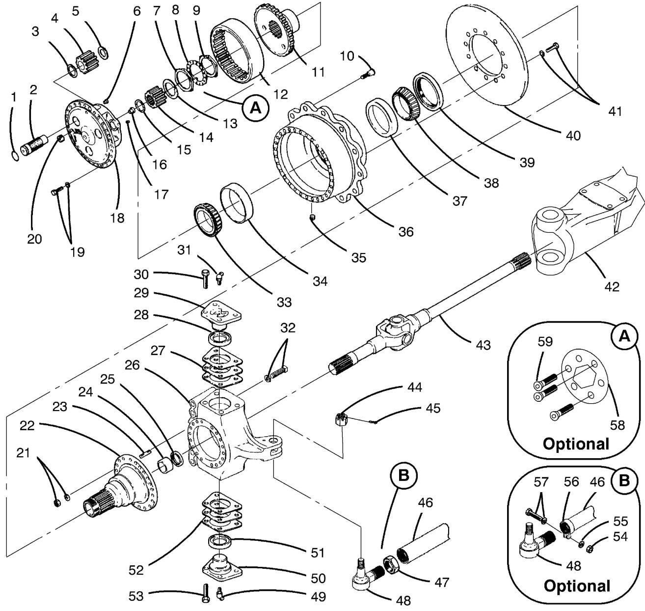
SM0l-004-015.00 FRONT AXLE, R & I
SM0l-007-028.00 STEER CYLINDER, RECON
SM0l-007-029.00 STEER CYLINDER, R & I
SM0l-018-060.00 TRANSMISSION, RECON
SM0l-018-061.00 TRANSMISSION, R & I
SM0l-022-004.00 U-JOINT INSTALLATION
(HALF ROUND YOKES)
SM0l-043-051.00 COMBINATION STEERING CONTROL VALVE, R & I
SM0l-043-052.00 O/R DIRECTIONAL CONTROL VALVE, R & I
SM0l-044-027.00 OUTRIGGER LOCK VALVE
CARTRIDGE, R&I AND RECON
SM0l-045-055.00 OUTRIGGER BEAM CYLINDER, RECON
SM0l-045-061.00 OUTRIGGER BEAM AND BEAM CYLINDER, R & I
SM0l-046-047.00 JACK CYLINDER, R & I
SM0l-046-048.00 JACK CYLINDER, RECON
SM0l-047-034.00
SM0l-022-005.00
SM0l-029-033.00
SM0l-030-018.00
SM0l-030-019.00
SM0l-039-003.00
SM0l-039-005.00
SM0l-039-009.00
SM0l-043-001.00
SM0l-043-003.00
SM0l-043-004.00
U-JOINT INSTALLATION (FULL ROUND YOKES)
REAR AXLE & SUSPENSION, R & I
PARK BRAKE CALIPER AND ACTUATOR, R & I
PARK BRAKE CALIPER AND ACTUATOR, RECON HYDRAULIC SYSTEM CLEANING
HYDRAULIC RESERVOIR FILTE ASSY, RECON
HYDRAULIC RESERVOIR FILTE
R & I
SOLENOID VALVES, GENERAL RECONDITION
O/R SOLENOID VALVE STACK, RECON
4-WAY SOLENOID VALVE, REC
SM0l-043-030.00 COMBINATION STEERING CONTROL VALVE, RECON
SM0l-043-050.00 OUTRIGGER FUNCTION CONTROL VALVE, R & I
SM0l-050-010.00
SM0l-050-011.00
SM0l-066-000.00
SM0l-066-029.00
SM0l-069-005.00
SM0l-077-013.00
SM0l-077-034.00
SM0l-078-018.00
SM0l-078-025.00
SM0l-078-026.00
SM0l-078-027.00
SM0l-079-042.00
SM0l-079-079.00
SM0l-080-049.00
SM0l-081-014.00
RELIEF VALVE, RECON REMOTE TRANSMISSION OIL COOLER, R & I
HYDRAULIC OIL COOLER, R & ELECTRICAL SYSTEM WIRE IDENTIFICATION CODE
BATTERY, R & I
TIRE & RIM, R & I
STARTER, R & I
CAC & RAD, R & I
OSCILLATION CYLINDER, REC AXLE OSCILLATION
CYLINDER, R & I
AXLE OSCILLATION LOCKOUT MANIFOLD, R & I
AXLE OSCILLATION LOCKOUT MANIFOLD, ILLUSTRATED
LOWER HYDRAULIC COMP, R&I (O/R, STEER, AXLE OSC)
LOWER HYDRAULIC COMP, R&I (SUCTION, PRESS, RETURN)
® Link-B lt s ar gist r<1d trad mark
SM0l RUBBER TIRE LOWER SM06 UPPER ENGINE
SM0l-081-037.00 HYDRAULIC PUMP, RECON SM06-025-022.00 HEATER CORE & A/C EVAP
SM0l-081-046.00 HYD GEAR PUMP/MOTOR, RECO COIL, ILLUSTRATED
SM0l-081-047.00 HYDRAULIC GEAR PUMP, R&I SM06-025-025.00 OPERATOR'S CAB HEATER (1-SECTION - WINCH) CORE, R & I
SM0l-081-048.00 HYDRAULIC GEAR PUMP, R&I SM06-025-026.00 DIESEL COOLANT HEATER, (BH, TELE, & WINCH) TROUBLESHOOTING & RECON
SM0l-081-055.00 HYDRAULIC GEAR PUMP, R&I (O/R, BRAKE, STEER, SWING
SM0l-081-061.00 HYDRAULIC VANE PUMP, RECO
SM0l-081-070.00 2-SECTION GEAR PUMP, R &
SM0l-081-071.00 2-SECTION GEAR PUMP, RECO
SM03 UPPER FRAME & MACHY
******************************************
SM03-001-073.00 UPPER REVOLVING FRAME & TURNTABLE BEARING, R & I
SM03-003-019.00 COUNTERWEIGHT, R & I
SM03-010-025.00 CTWT REMOVAL CYL, RECON
SM03-010-045.00 COUNTERWEIGHT REMOVAL
CYLINDER, R & I
SM03-010-046.00 CTWT REMOVAL SOLENOID CONTROL VALVE, R & I
SM03-010-048.00
CTWT REMOVAL SOLENOID CONTROL VALVE, RECON
SM04 VERTICAL SHAFTS
SM06-025-027.00 DIESEL COOLANT HEATER, R & I
SM07 UPPER HYDRAULICS & AIR
SM07-002-032.00 RELIEF VALVE, RECON
SM07-003-006.00 SOLENOID VALES, RECON
SM07-004-036.00 UPPER HYDRAULIC COMPONENT
R & I
SM07-006-095.00 WINCH MOTOR, RECON
SM07-006-107.00 WINCH MOTOR, R & I
SM07-008-107.00 DUAL AXIS CONTROLLER VALVE, RECON
SM07-008-116.00 DUAL AXIS CONTROLLER
VALVE, R & I
SM07-008-122.00 WINCH COUNTERBALANCE VALVE, RECON
SM07-008-132.00 CONTROL VALVE, RECON
SM07-008-135.00 WINCH CONTROL VALVE, R &
SM07-008-140.00 WINCH COUNTERBALANCE
****************************************** VALVE, R & I
SM04-005-034.00 SWING BRAKE, R & I
SM04-005-035.00 SWING BRAKE, RECON
SM17 HYDRAULIC BOOM
SM04-010-035.00 SWING REDUCTION UNIT, REC ******************************************
SM04-010-036.00 SWING REDUCTION UNIT, R&I SM17-001-053.00 HYDRAULIC BOOM INSPECTION (FORMED BOOMS)
SM0S HORIZONTAL SHAFTS
SM17-001-081.00 FIVE SECTION LATCHING BOOM
****************************************** ,R & I
SM0S-006-026.00 WINCH, TROUBLESHOOTING
SM0S-006-028.00 WINCH, RECON
SM17-001-082.00 FIVE SECTION LATCHING BOO
SM17-002-054.00 BOOM TELESCOPE COUNTER BA
SM0S-006-035.00 WINCH ASSEMBLY, R & I
SM17-002-065.00 LATCHING BOOM TELE SYSTEM
SM17-002-055.00 BOOM TELESCOPE CYLINDER, SM0S-018-006.00 WINCH ROLLER, R& I AND SM17-002-059.00 TELESCOPE CYLINDER LENGTH RECON
SM17-002-066.00 BOOM LATCHING/PINNING CYL
SM17-002-069.00 BOOM LATCHING CYLINDER, R ******************************************
SM06 UPPER ENGINE
SM17-002-088.00 HOSE & CABLE REEL, RECON
SM06-025-021.00 OPERATOR'S CAB A/ COIL & MOTOR
HEATER CORE, R & I
SM17-002-089.00 BOOM TELE SYSTEM MECHANIS
SM17-002-108.00 LATCHING BOOM TELE SYSTEM
SM17 HYDRAULIC BOOM
******************************************
SM17-002-109.00 LATCHING BOOM SYSTEM, CAL
SM17-002-114.00 HOSE & CABLE REEL, R & I
SM17-002-115.00 TELE CYLINDER LENGTH REEL
SM17-002-118.00 PIN/LATCH VALVE, RECON
SM17-003-013.00 BOOM HOISTCYLINDER, RECON
SM17-003-039.00 BOOM HOIS CYLINDER, R & I
SM17-003-040.00 BOOM HOIST COUNTERBALANCE
SM17-003-055.00 BOOM HOIST COUNTERBALANCE
SM17-009-004.00 FIVE SHEAVE HEAD
MACHINERY, RECON
SM18 SPECIAL ATTACHMENTS ******************************************
SM18-007-016.00 REELING DRUM, TRBL & RECO
SM18-007-021.00 REELING DRUM, R & I
SM18-018-001.00 AIR CONDITIONING SERVICE
PRECAUTIONS
SM18-018-004.00 A/C COMPRESSOR, RECON
SM18-018-013.00 A/C COMPRESSOR, R & I
SM18-018-014.00 A/C HYDRAULIC DRIVE
MOTOR, R & I (UPPER)
SM18-018-015.00 A/C HYDRAULIC DRIVE
® Link-B lt s ar gist r<1d trad mark
SERIAL NO. - N4K9-4695 4/28/20
SM CODE DESCRIPTION
DATE
How To Use This Manual, General Service Instructions, And Safety Procedures
The following information is provided to help guide the user of this manual. An explanation of how this manual is organized, as well as general information and safety considerations which should be understood when performing any service or maintenance procedure, is given. This information is general in nature and should supplement any of the specific procedures in this manual along with a constant awareness of safety and common sense.
How To Use This Manual
This Service Manual is a collection of written procedures which are used to service and maintain a specific crane model. The index, which is called a "Keysheet", is used to organize the procedures within this manual and serve as a Table Of Contents as well. Each procedure, in this manual, is written so that it can stand alone and typically covers only one procedure. Procedures are given a numerical designation, or "SM Code" Number, (Example: SM01 -005-034.00) which is unique to that procedure and that procedure only. The following is a listing of the general area definitions which are designated by the first digits in the SM Code Number sequence:
General Area Descriptions
SM01 - Rubber Tire Lower
SM02 - Crawler Lower
SM03 - Upper Revolving Frame & Machinery
SM04 - Vertical Shafts
SM05 - Horizontal Shafts
SM06 - Upper Engine
SM07 - Hydraulic Power Supply
SM08 - Angle Boom
SM09 - Tubular Boom
SM10 - Tagline Winder
SM11 - Fairleader
SM12 - Shovel Attachment
SM13 - Trench Hoe, Logger & Scrapper Attachment & Prop Handler
SM14 - Cab & House Assembly
SM15 - Rotascope Attachment (Discontinued)
SM16 - Wire Rope Requirements
SM17 - Hydraulic Boom And Attachments
SM18 - Special Attachments
SM19 - Diesel Pile Hammer (Discontinued)
SM20 - Tower, Climbing Assembly, Traveling Base & Gantry (Discontinued)
SM21 - Log Skidder (Discontinued)
SM22 - Hydraulic Hammer (Discontinued)
The procedures in this manual are collated by SM Code Number sequence. Use the Keysheet in the front of this manual, the general area descriptions shown previously, and the SM Code title shown on the
Keysheet to find the specific procedure required to service the crane.
Throughout this manual, reference is made to the left, right, front, and rear, pertaining to directions and locations. These reference directions are relative to the operator, sitting in the operator's seat, with the upper directly over the front of the carrier, unless otherwise stated. (Crawler mounted cranes: upper over the front of the crane with travel motors to the rear.)
Danger, warning, and caution captions as well as special notes are used throughout this manual and on the crane to emphasize important and critical instructions. If any instruction, caution, warning, or danger labels, decals, or plates become lost, damaged, or unreadable, they must be replaced. Information contained on such labels, decals, and plates is important and failure to follow the information they contain could result in an accident. Replacement labels, decals, and plates can be ordered through a Link-Belt Distributor. For the purpose of this manual, danger, warning, and caution captions and notes are defined as follows:
Notes
Note: Anoperating procedure step,condition, etc. which is essential in order for the process to be completed properly.
Thissymbolmayappearinmanualsoronalabelon the crane to alert personnel that additional instructions are included in the crane Operator's Manual.
Service Safety And Set Up Guidelines
The following is a list of safety and set up considerations which may apply to any service or maintenance procedure. Review the entire list and understand the type of things you must consider to perform a safe service procedure and then apply these guidelines to each specific service or maintenance procedure.
Danger
Service Safety
1. Read and understand the service or maintenance procedure to be performed before beginning work. By reading the procedure ahead of time, you can be sure to have the replacement parts and tools on hand that are required to complete the job.
2. Wear protective gear to prevent injury; hard hat, safety glasses, gloves, steel toed shoes, etc.
3. First aid supplies and a fire extinguisher should be on the job site to assist in an unexpected situation. The location of these items should be known to all as well as access to a telephone for emergencies.
4. Work in a clean, dry, firm, level area whenever possible. Choosing the correct work site can make a big difference on how well the job goes.
5. Use caution around flammable materials. Be aware of all the materials in the work area which are a threat. Also make others aware of volatile materials; post signs if necessary.
6. Release all trapped pressure in air and hydraulic circuits before disconnecting any line or component. Shutdown the crane, exhaust all pressure from the crane's air reservoir(s) and work the hydraulic control levers back and forth before servicing the crane.
7. Do not disconnect any hydraulic line from a crane which has its attachment in the air. Trapped pressure may be all that is suspending it. Disconnecting a line could release the trapped pressure, causing the attachment to fall. Lower the attachment to the ground or on to its rest before servicing the crane.
8. Do not work on a crane which is in motion Fans, belts, gear trains, etc. can catch an unexpecting person and quickly dismember them.
9. Do not climb on the attachment or other hard to reach areas. If the steps and/or ladders which are installed on the crane do not provide adequate access to the area of the crane which needs servicing, use a step ladder or other approved device.
10. Pinch points exists between the upper and lower frames. Death or dismemberment may result from personnel caught in these points. Learn where these pinch points are and stay clear of the rotating upper frame.
11. If working in a confined area, be sure to provide adequate ventilation when running the engine(s), using toxic solvents, welding, or any other operation which contaminates the fresh air supply.
12. Post a sign in the operator's cab to alert others that the crane is under service. Starting the crane while it is being serviced could severely injure someone Crane damage could also occur if systems are operated prematurely Imagine starting the engine(s) before the oil is replaced.
13. Secure access panels, doors, and machinery hoods when in the open position to ensure they do not fall or slam shut due to wind or accidental disruption.

14. Crane parts may be heavy. Always use an appropriate lifting device to support work. Do not attempt to lift an object without knowing its weight. Get help if necessary.
15. Always use a safety rim cage when inflating or deflating tires. Worn or misassembled parts can "explode" from the assembly causing serious injury. Use a safety rim cage, clip on air chuck, and stand aside when inflating or deflating tires.
Crane Set Up And Disassembly
1. Properly park the crane as described in the Operator's Manual. Park the crane in an area which provides the most comfortable working conditions. However, do not park the crane where it will be an obstruction or an intrusion to traffic, coworkers, or to the public Keep in mind that a major service procedure, or a repair part which requires a long lead time, could have the crane disabled for an extended period of time.
2. Keep in mind the mess which is sometimes caused by a crane under repair. Oil or other fluid leaks should be contained or prevented. Consider your responsibility of maintaining a safe clean work area and a healthy environment for all.
3. If the crane is equipped with outriggers, it may be safer as well as an advantage to raise and level the crane on outriggers to provide easier access to areas underneath. Do not work under a crane that is improperly supported.
4. Shutdown the engine(s) per the instructions given in the Operator's Manual.
5. Post a sign in the operator's cab to alert others that the crane is being serviced.
6. Engines, transmissions, hydraulic systems, etc. generate extreme heat during operation. Temperatures can reach levels which may cause serious burns. Allow the crane to cool before attempting to service it.
A7. Pressure is generated inside the engine's cooling system due to the heat transfer process from the engine(s) to the radiator(s). Do not attempt to open or drain the radiator(s) until it/they has/have had sufficient time to cool. Disconnecting hoses before the engine(s) and radiator(s) has/have cooled is even more dangerous. Wait until the engine(s) and radiator(s) have cooled and then drain the radiator(s) before disconnecting any hoses. Properly store or dispose of used coolant.
8. Thoroughly clean the area of the crane which is to be serviced. Dirt or other contamination could enter the hydraulic, air, lubricating system, etc. and cause immediate and/or long term problems. Cleaning the service area not only prevents contamination problems but it also makes working on the crane easier and sometimes problems are more recognizable.
9. Before beginning any removal or disassembly procedure, take a moment to observe critical features of the assembly which may greatly simplify the installation or assembly process. Label electrical, hydraulic, air, or other connections. Index mark pump, motor, and valve sections. Lightly spray paint or count the threads of adjustment screws. Simple steps such as these can minimize the effort needed to put the crane back in service
10. Hydraulic systems, while operating, are under high pressure. Even after the crane is shutdown these pressures can remain trapped in the hydraulic lines and system components. Some hydraulic systems utilize an air pressurized reservoir which maintains pressure on the system after the crane is shutdown. It is critical that all residual pressure, which is trapped in the system, be neutralized before disconnecting any line or hydraulic component. Use the following techniques to exhaust trapped hydraulic pressure from the system: a. Lower the attachment to the boom rest, onto blocking, or onto the ground and shutdown the engine(s). b. Open the drain valves on the air system reservoir(s), if equipped, to bleed the air system pressure. c. Relieve any residual or precharge pressure by pushing the button on the pressure relief valve, on the hydraulic reservoir, if equipped. Otherwise, loosen the filler cap 1/4 turn. d. Turn the ignition switch to the ON POSITION, but DO NOT START THE ENGINE. e. Operate the steering control(s) back and forth repeatedly until steering becomes hard. (On cranes equipped with emergency steering system, it will take several rotations of steering wheel before steering becomes hard.) f. Work the crane control levers and outrigger switches, if equipped, back and forth several times. g. Turn ignition switch to the OFF POSITION. h. When pressure is fully relieved, close the drain valves on the air system reservoir(s), if equipped. battery connecting volatile and causing around the the hazard. related lead lead poisoning. products.
11. Air system circuits, like hydraulic circuits, contain high pressures also. Although the threat of a hot working fluid does not exist, highly pressurized lines and components can possibly "fly off" if lines are disconnected before the system pressure is relieved. Open the drain valve on the air system reservoir(s) to exhaust system pressure before working on the crane.

12. When working on electrical circuits, disconnect the battery to minimize shock, burn, spark, or other hazard. When disconnecting the battery, confirm that the ignition switch is in the "OFF" position. Disconnect the negative side of the battery first to minimize the potential for sparks at the battery. Battery gases which are exposed to such sparks, could cause an explosion. Likewise when connecting the battery, confirm that the ignition switch is in the "OFF" position and install the positive cable(s), first and the negative connection(s) last.
13. It is a good practice when disassembling hydraulic components to lay the parts out in the order that they were disassembled. Keeping the parts in this order during disassembly, cleaning, and inspection will aid in the assembly process.
Welding
1. When making repairs which require welding, disconnect any electronic equipment (such as rated capacity limiters and engine computers) to prevent damage to them. Use the battery disconnect switch(es), if equipped.
2. Be aware of systems adjacent to areas being welded. Residual heat from the welding process could cause damage to other components. Heat may also vaporize materials which may become toxic or volatile.
3. Remove paint from areas to be welded to prevent toxic fumes.
4. The grounding connection should be within 3 feet (1 m) of the welded parts.
5. Connect the ground to the lower, if welding on the lower, or to the upper if welding on the upper. Electrical current through the turntable bearing could cause an arc which could damage it.
6. Do not position the ground connection where seals or bearing, as in transmissions or valves, will be between it and the welded parts
7. Remove any flammable materials from the area.
8. Use the appropriate setting on the welder for the size of the welding operation. Do not use more than 200 Volts continuously.
Cleaning And Inspection
AWARNING solutions.
be may Read manufacturer's solvents and
1 All components should be thoroughly cleaned with an approved cleaning solvent, air dried and carefully inspected for damage, wear and corrosion.
2. All Loctite® or other sealant residue should be removed from threads of hardware and parts that are going to be reused.
3. All "soft parts", such as seals, gaskets, back up rings, and o-rings, should be replaced.
4. Replacement of bearings and bushings is generally a good preventive maintenance measure. Even though a bearing or bushing seems to be intact and is functioning properly, its life span is limited. Replacing a simple bearing or bushing while the opportunity is at hand could save a complete component failure later.
5. In the event of severe defects, contact factory personnel for directions whether to repair or replace any major component.
Crane Assembly
1. Loosely assemble parts to ensure all parts are in place and fasteners started before beginning torquing procedure. Always use a cross torquing sequence to ensure even and uniform installation
2. Unless otherwise stated, torque all fasteners per the instructions given in SM Code Area 18-000.
3. When installing hydraulic hoses, lines, and fittings, use two wrenches to ensure the hoses and lines are not twisted One wrench must be on the male fitting, the other wrench on the female fitting.
4. Unless otherwise stated, torque all hydraulic fittings per the instructions given in SM Code Area 07-018.
5. Check all fluid levels before returning the crane to service; hydraulic reservoir oil level, transmission fluid level, engine(s) oil level, etc. Add oil as required. See Operator's Manual and/or engine(s) manufacturer's manual(s) for correct type of fluids and procedures.
6. Always replace guards, grilles, and other types of protective shields. Also, be sure that any systems which were disconnected such as load indicating systems, anti-two block devices, control cables, etc. are functioning properly before returning the crane to service.
7. Start the appropriate engine and let it idle for five minutes. Inspect the connections on the hydraulic, air, transmission, etc. lines for leaks. Repair if needed.
8. Check that all hydraulic, air, and electrical functions are operating normally before returning the crane to service.
9. After crane is assembled, refer to the Operator's Manual for any periodic type of adjustments which may have been affected by the service procedure.
10. Properly dispose of any used oils, solvents, cleaners, etc.

