DOWNLOAD LINK
For some reason if link does not work download this pdf and then click
Product: GENERATOR SET
Model: 3516 GENERATOR SET 8TW
Configuration: 3516 Generator Set 8TW00001-UP
Operation and Maintenance Manual
SR4 and SR4B Generators and Control Panels
Media Number -SEBU7050-10
Air Inlet Filter - Check
SMCS - 1051-535
-01/11/2004 Date Updated -02/11/2004
Monitor the connector contacts of the differential pressure switch for the air inlet filter. If the differential pressure rises above 15.2 mm (0.6 inch) of water, clean the filter with a solution of soap and water. Be sure that the filter is thoroughly dry before the start-up. Replace the filter, if necessary.
Copyright 1993 - 2024 Caterpillar Inc. All Rights Reserved. Private Network For SIS Licensees.
Thu Oct 17 09:24:32 UTC+0530 2024
i01189973
Product: GENERATOR SET
Model: 3516 GENERATOR SET 8TW
Configuration: 3516 Generator Set 8TW00001-UP
Operation and Maintenance Manual
SR4 and SR4B Generators and Control Panels
Media Number -SEBU7050-10
Bearing - Inspect
SMCS - 4471-040
-01/11/2004
-02/11/2004
The following maintenance procedure for generator bearings should be followed at every major engine overhaul:
1. Remove the bearing bracket. Inspect the following items: bracket bore, bearing outer race and rolling elements. On standby power units, the bearing must be inspected and the grease must be replaced at three year intervals. The sleeve for the bearing bracket should be inspected for out of roundness, excessive wear, and a bracket step that is less than 0.0762 mm (0.0030 inch). If there is no sleeve for the bearing bracket, inspect the bore for the bearing bracket. The bearing should be inspected for damage to the outer race, severe fretting, and smoothness of operation. When possible, the bearing elements should be inspected. Some double shielded ball bearings prevent visual inspection of the ball bearings. Other double shielded ball bearings have a retaining ring. This retaining ring can be removed in order to allow access for a visual inspection of the ball bearings.
On two-bearing generators, the front bearing can only be removed after the hub is removed. In order to remove the hub, cut off the hub. Pulling the hub will damage the shaft.
Note: Bearings that are being removed for failure analysis should not be cut off with a torch.
2. Spherical Roller Bearing should be cleaned and repacked with 108-8611 Grease. Pack the bearing and pack the cavity (one-third to one-half of the volume of the cavity). The bearing should be filled with 88.8 mL (3 ounces) to 118.4 mL (4 ounces) of grease. The cavity should be filled with 118.4 mL (4 ounces) to 148.0 mL (5 ounces) of grease. Refer to Table 1.
3. All ball bearings should be cleaned. The cavity of the bracket should be repacked with 2S3230 Grease. Pack the bearings (one-third to one-half of the volume of the cavity). Refer to Table 1.
To reinstall bearings, heat the bearings to 107 °C (224.6 °F) for ten minutes. Mount the bearings on the shaft. To reinstall the hub, heat the hub to 400 °C (752.0 °F) for three hours. Mount the hub to the shaft.
i02230503
4. Ensure that the tube that supplies grease to the bearing is filled with grease.
5. Remove the bracket drain plug and operate the generator for one hour. This will allow the grease to expand. The expanding grease will force the excess grease from the cavity. When the excess grease is forced from the cavity, the internal pressure will be reduced. The generator should continue to operate until the grease stops purging.
6. Stop the engine. Install the bracket drain plug. Wipe off the excess grease.
7. For greasing intervals, follow the recommendations on the lubrication plate (if equipped) or refer to Maintenance Schedul¥, "Bearing - Lubricate". Whenever the bearings are greased, repeat Step 5. DO NOT MIX GREASES.
Table 1
mm (5.5118 inch) 65.000 mm (2.5591 inch) 3N-1965 440 (round laminated)
mm (5.5119 inch) to 140.028 mm (5.5129 inch)
mm (6.2992 inch) 75.000 mm (2.9527 inch) 5P-2448 580 (2) 590 (1) 160.002 mm (6.2993 inch) to 160.028 mm
(6.3003 inch) (2.9536 inch) 170.000 mm (6.6929 inch) 80.000 mm (3.1496 inch) 4L6677 (3) 580 (1)
mm (6.6930 inch) to 170.028 mm (6.6940 inch)
mm (6.6929 inch)
mm (3.1496 inch) 1097687 (3) 580 (1)
inch) to
mm (6.6940 inch)
mm (3.1497 inch) to
mm (3.1504 inch)
mm (3.1497 inch) to
mm (3.1504 inch) 180.000 mm (7.0866 inch)
mm (3.9375 inch) to
mm (3.9381 inch) 190.000 mm (7.4803 inch) 90.000 mm (3.5433 inch) 6Y-6488 590 (1) 589 PM
mm (3.5444 inch)
mm
mm 6V-0410 680 (1)
(8.8582 inch) (4.1338 inch) (8.8584 inch) to 225.034 mm (8.8596 inch) oz) to
225.000 mm (8.8582 inch) 105.000 mm (4.1338 inch) 1081760 680 (1) 225.003 mm (8.8584 inch) to 225.034 mm (8.8596 inch)
230.000 mm (9.0551 inch) 130.000 mm (5.1181 inch) 2L4444 (4) 808 4 pole (1) 229.992 mm (9.0548 inch) to 230.022 mm (9.0560 inch)
230.000 mm (9.0551 inch) 130.000 mm (5.1181 inch) 2L4444 (4) 820 (1) 229.992 mm (9.0548 inch) to 230.022 mm (9.0560 inch) Open 236.8 mL (8.0 oz) to 355.20 mL (12.0 oz)
240.000 mm (9.4488 inch) 110.000 mm (4.3307 inch) 1081761 690 (1) 240.002 mm (9.4489 inch) to 240.033 mm
inch) to
mm (4.1352 inch)
mm (5.1201 inch)
mm (5.1192 inch) to 130.051 mm (5.1201 inch)
mL (7.0 oz) to 296.00 mL (10.0 110.012 mm (4.3312 inch) to 110.028 mm
inch)
mm (9.4488 inch)
mm (11.0249 inch)
mm (5.1201 inch)
( 1 ) Inboard bearing
( 2 ) Outboard bearing
( 3 ) 109-7687 bearing is preferred.
( 4 ) This bearing is a spherical roller bearing. This bearing is greased from the bracket's front side. All of the other bearings are ball bearings.
( 2 ) This bearing is on the same end as the exciter.
( 3 ) This bearing is on the drive end of the generator.
Copyright 1993 - 2024 Caterpillar Inc. All Rights Reserved. Private Network For SIS Licensees. Thu Oct 17 09:24:44 UTC+0530 2024
Product: GENERATOR SET
Model: 3516 GENERATOR SET 8TW
Configuration: 3516 Generator Set 8TW00001-UP
Operation and Maintenance Manual
SR4 and SR4B Generators and Control Panels
Media Number -SEBU7050-10
Bearing - Lubricate
SMCS - 4471-086
Ball Bearings
For ball bearings, use Caterpillar 2S-3230 Special Purpose Grease (SPG). This grease is an NLGI No. 2 Grade. There is Polyurea (a thickener) in this grease. The temperature range of Caterpillar 2S-3230 low temperatures, use either NLGI No. 1 Grade or NLGI No. 0 Grade.
Use 56.7 grams (2 ounces) of grease. Refer to the Lubrication Plate.
Note: On standard applications, ball bearings should be lubricated at 2000 hour intervals.
Note: On standby applications, ball bearings should be lubricated once per year.
Spherical Roller Bearings
For spherical roller bearings, use Caterpillar 108-8611 Grease. This grease is an NLGI No. 1.5 Grade. There is no molybdenum disulfide in this grease. There is Clay (a thickener) in this grease. At 40 °C (104.0 °F), the viscosity of Caterpillar 108-8611 Grease is 32 cSt. At 100 °C (212.0 °F), the viscosity is 5 cSt.
Use 28.3 grams (1 ounce) of grease. Refer to the information on the Lubrication Plate.
Note: On standard applications, spherical roller bearings should be lubricated at 1000 hour intervals.
Note: On standby applications, spherical roller bearings should be greased once per year.
Lubrication Procedure
1. Remove either the louver assembly or the rear plate from the rear of the generator housing.
i02044911
2. Remove the top grease pipe plug and remove the lower grease pipe plug.
3. Install a grease fitting in the grease pipe.
4. Grease the shielded ball bearings with 2S-3230 Grease (53.28 mL (1.8 ounces) to 59.20 mL (2.0 ounces)). Lubricate shielded ball bearings at 2000 hour intervals. Grease spherical roller bearings with 108-8611 Grease (29.6 mL (1 ounce)). Spherical roller bearings should be lubricated at 1000 hour intervals. Do not mix greases.
Note: Some two-bearing generators have spherical roller bearings in the front bracket and ball bearings in the rear bracket. These units should use a common 108-8611 Grease. This grease should be used for the front bearing and the rear bearing.
5. Wipe off the excess grease. Remove the top grease fitting. Install the plug.
6. Operate the generator for one hour. This will allow the grease to expand. The expanding grease will force the excess grease from the cavity. When the excess grease is forced from the cavity, the internal pressure will be reduced. The generator should continue to operate until the grease stops purging.
7. Stop the engine. Install the plug in the bottom grease pipe. Wipe off the excess grease.
8. Install the louver assembly or install the rear plate. Copyright 1993 - 2024 Caterpillar Inc.
Rights Reserved.
Network For SIS Licensees. Thu Oct 17 09:25:00 UTC+0530 2024
Product: GENERATOR SET
Model: 3516 GENERATOR SET 8TW
Configuration: 3516 Generator Set 8TW00001-UP
Operation and Maintenance Manual
SR4 and SR4B Generators and Control Panels
Media Number -SEBU7050-10
-01/11/2004
Bearing Temperature - Measure/Record
SMCS - 4471-082-TA
-02/11/2004
i01189927
Bearing temperature detectors are optional on all SR4B generators. These detectors are 100 Ohms resistance temperature detectors. Bearing temperature detectors are used with equipment that has been provided by the customer in order to measure the bearing temperature. Bearing temperature detectors may help to prevent premature bearing failure.
A bearing temperature above 70 °C (158 °F) may require a change in operation. The unit should be shut down in order to prevent or minimize the damage if the bearing temperature reaches 85 °C (185 °F).
Copyright 1993 - 2024 Caterpillar Inc. All Rights Reserved. Private Network For SIS Licensees.
Thu Oct 17 09:25:12 UTC+0530 2024
Product: GENERATOR SET
Model: 3516 GENERATOR SET 8TW
Configuration: 3516 Generator Set 8TW00001-UP
Operation and Maintenance Manual
SR4 and SR4B Generators and Control Panels
Media Number -SEBU7050-10
Date -01/11/2004 Date Updated -02/11/2004
Electrical Connections - Check
SMCS - 4459-535
Check all exposed electrical connections for tightness.
Check the following devices for loose mounting or for physical damage:
• transformers
• fuses
• capacitors
• lightning arrestors
Check all lead wires and electrical connections for proper clearance.
Copyright 1993 - 2024 Caterpillar Inc. All Rights Reserved. Private Network For SIS Licensees. Thu Oct 17 09:25:25 UTC+0530 2024
i08259823
Product: GENERATOR SET
Model: 3516 GENERATOR SET 8TW
Configuration: 3516 Generator Set 8TW00001-UP
Operation and Maintenance Manual
SR4 and SR4B Generators and Control Panels
Media Number -SEBU7050-10
-01/11/2004
General Maintenance Information
SMCS - 4450
Updated -02/11/2004
Note: Read the warnings and read the instructions that are contained in the Safety Section of this manual. These warnings and instructions must be understood before you perform any operation or any maintenance procedures.
Rotating electric machines are complex structures that are exposed to the following forms of stress:
• mechanical
• electrical
• thermal
• environmental
These stresses may be of varying magnitudes. The electrical insulation systems are susceptible to damage that is caused by the stresses that are listed above. Exposure to these stresses may shorten the effective life of the electrical insulation system. Therefore, the service life of an electric machine will largely depend on the serviceability of the electrical insulation systems. An inspection program and a testing procedure are recommended. An inspection program and a testing procedure will ensure that the equipment is maintained in satisfactory condition. Maintaining the equipment will increase field reliability.
A regular maintenance and inspection program can provide an evaluation of the present condition of the equipment. A regular maintenance program and a regular inspection program can also reveal future problems. The frequency of this maintenance program will depend on the following factors:
• application
• environmental conditions
• experience level of the operator
i08259062
• philosophy of the operator
A regular maintenance program is recommended. This program would involve the following steps:
• periodic disassembly
• knowledgeable visual examination of the equipment
• the application of electrical tests
Never perform a test over the rated potential. These tests can damage insulation that is contaminated or insulation that is in marginal condition. For more information, refer to "I.E.E.E. Standard 432-1992" or consult a Cat dealer.
Copyright 1993 - 2024 Caterpillar Inc. All Rights Reserved. Private Network For SIS Licensees. Thu Oct 17 09:23:34 UTC+0530 2024
Product: GENERATOR SET
Model: 3516 GENERATOR SET 8TW
Configuration: 3516 Generator Set 8TW00001-UP
Operation and Maintenance Manual
SR4 and SR4B Generators and Control Panels
Media Number -SEBU7050-10
Generator - Dry
SMCS - 4450-569
-01/11/2004
-02/11/2004
Personal injury or death can result from improper troubleshooting and repair procedures.
The following troubleshooting and repair procedures should only be performed by qualified personnel familiar with this equipment.
Refer to Safety Section, "Generator Isolating for Maintenance" for information regarding the procedure to isolate the generator safely.
If the insulation resistance values are less than the recommended values, one of the following drying procedures must be selected. This decision should be based on the following factors:
• the size of the unit
• the location of the unit
• the equipment that is available
• the experience of personnel
Note: For more information on drying methods, refer to Special Instruction, SEHS9124, "Cleaning and Drying of Electric Set Generators".
Remove the voltage regulator. Cover all inlet openings. Cover all discharge holes. Provide an opening at the top of the machine. This opening will allow moisture to evaporate. Preferably, this opening will be at the fan end. Monitor the winding temperatures. DO NOT APPLY HEAT TOO RAPIDLY. Winding temperature should be raised gradually at a rate of 10 °C (50 °F) per hour up
i08259828
to 85 °C (185 °F). Measure insulation resistance in 1-hour intervals. Typically, the insulation resistance will slowly drop while the temperature is rising. The insulation resistance will then start to increase at a slow rate until the insulation resistance reaches a constant level.
The following methods can be used for drying a generator:
• Self-circulating air method
• Oven method
• Controlled current method
Self-Circulating Air Method
Run the engine and disconnect the generator load. Running the engine will help circulate air. Operate the generator space heaters.
Oven Method
Place the entire generator inside a forced air drying oven for 4 hours at 65 °C (149 °F).
NOTICE
Use a forced air type oven rather than a radiant type oven. Radiant type ovens can cause localized overheating.
Controlled Current Method
Table 1
Tools Needed
Part Number Description Qty
225-8266 Ammeter Tool Gp 1
External Power Source 1
Rheostat 1
Heat can be used to dry the generator windings. This heat can be created by allowing a controlled current to flow through the generator. No high voltages are generated during the following procedure. Therefore, insulation breakdown will not occur.
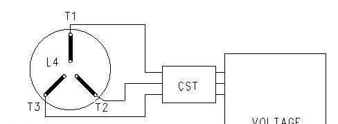
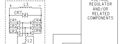
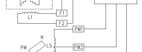
Illustration 1 g00669571
Generator Wiring Diagram
(CR1-CR6) Diodes (CR7) Varistor
(L1) Exciter field (stator)
(L2) Exciter armature (rotor)
(L3) Main field (rotor)
(L4) Main armature (stator) (L5) Pilot exciter armature (PM) Permanent magnet (RFA) Rotating field assembly (CST) Customer supplied transformer
1. Make an external power source.
2. Refer to the above diagram. Disconnect "F1+" from the voltage regulator. Disconnect "F2-" from the voltage regulator. Disconnect the generator load. Connect the generator output
leads "T0", "T1", "T2", and "T3". Install the clamp-on ammeter to generator output lead "T1".
Note: When the line current is measured on multiple-lead units, measure the current in each conductor per phase. The currents can then be added.
3. Refer to the above diagram. Connect the rheostat. Adjust the rheostat to the maximum resistance value. Connect the external power source to wires "F1+" and "F2-".
4. Start the generator set. Run the generator set at IDLE speed.
5. Monitor the phase current. Gradually increase the engine RPM. Increase the engine RPM until one of the following conditions is met:
The rated phase current is obtained.
The full generator set speed is obtained.
6. If more phase current is still necessary, slowly turn the rheostat until the rated phase current is reached.
7. On an hourly basis, stop the drying procedure. Check the insulation resistance. Repeat the above steps until the insulation resistance is acceptable.
1993 - 2024 Caterpillar Inc.
Product: GENERATOR SET
Model: 3516 GENERATOR SET 8TW
Configuration: 3516 Generator Set 8TW00001-UP
Operation and Maintenance Manual
SR4 and SR4B Generators and Control Panels
Media Number -SEBU7050-10
Generator - Inspect
SMCS - 4450-040
-01/11/2004
-02/11/2004
Personal injury or death can result from improper troubleshooting and repair procedures.
The following troubleshooting and repair procedures should only be performed by qualified personnel familiar with this equipment.
Refer to Safety Section, "Generator Isolating for Maintenance" for information regarding the procedure to isolate the generator safely.
Proper maintenance of electrical equipment requires periodic visual examination of the generator and periodic visual examination of the windings. Proper maintenance of electrical equipment also requires appropriate electrical checks and appropriate thermal checks. Insulation material should be examined for cracks. The insulation material should be examined for accumulations of dirt and dust. If there is an insulation resistance value that is below normal, a conductive path may be present. This conductive path may be made of one of the following materials:
• Carbon
• Salt
• Metal dust
• Dirt that is saturated with moisture
These contaminants will develop a conductive path which may produce shorts. Cleaning is advisable if heavy accumulations of dirt can be seen or if heavy accumulations of dust can be
i05728320
seen. If excess dirt is the cause of a restriction in the ventilation, cleaning is also advisable. Restricted ventilation will cause excessive heating.
NOTICE
To avoid the possibility of deterioration to the generator windings, do not clean the generator unless there is visual, electrical, or thermal evidence that dirt is present.
If harmful dirt accumulations are present, various cleaning techniques are available. The cleaning procedure that is used may be determined by one of the items on the following list:
• The extent of the cleaning procedure that is being attempted
• The type of enclosure of the generator
• The voltage rating of the generator
• The type of dirt that is being removed
Cleaning (Assembled Generators)
Cleaning may be required at the point of installation. If complete disassembly of the generator is not necessary or feasible, a vacuum cleaner should be used to pick up the following items: dry dirt, dust and carbon. Vacuuming dust and dirt will prevent the spreading of these contaminants.
If necessary, connect a small nonconductive tube to the vacuum cleaner. A nonconductive tube will allow the vacuum cleaner to clean the surfaces that are not exposed. After most of the dust has been removed, a small brush may be attached to the vacuum hose in order to loosen firmer dirt.
After the initial cleaning with a vacuum, compressed air may be used to remove the remaining dust and dirt. Compressed air that is used for cleaning should be free of moisture and free of oil. Air pressure should be a maximum of 210 kPa (30 psi) in order to prevent mechanical damage to the insulation. If the above cleaning procedures are not effective, consult a Cat dealer.
Cleaning (Disassembled Generators)
An initial insulation resistance check should be made on the generator in order to confirm electrical integrity. A minimum reading of 1 megohm would be expected with severely contaminated generators. A zero megohm reading may indicate an insulation breakdown. An insulation breakdown requires more than cleaning. An insulation breakdown requires repair.
A high-pressure wash is normally an effective way to clean windings. Windings that have been exposed to flooding, or windings that have been contaminated by salt can be high-pressure washed as well. A solution of hot water and detergent is used for this method of cleaning.
A high-pressure wash sprays a high velocity fluid stream of this solution over the generator that is being cleaned. This detergent washing is followed by multiple sprays of clean water. The clean
water is used in order to remove the detergent or the clean water is used in order to dilute the detergent.
Allow the generator to dry at room temperature. Check the insulation resistance. The insulation resistance should now be normal. If the insulation resistance is not normal, repeat the procedure. Use of solvents may be necessary if the generator is contaminated with oil or if the generator is contaminated with grease.
Note: For more information on drying methods, refer to Special Instructions, SEHS9124, "Cleaning and Drying of Electric Set Generators".
1993 - 2024 Caterpillar Inc.
Oct 17 09:25:40 UTC+0530 2024
Product: GENERATOR SET
Model: 3516 GENERATOR SET 8TW
Configuration: 3516 Generator Set 8TW00001-UP
Operation and Maintenance Manual
SR4 and SR4B Generators and Control Panels
Media Number -SEBU7050-10
Generator Load - Check
SMCS - 4450-535-LA
During normal operation, monitor the power factor and monitor generator loading.
When a generator is installed or when a generator is reconnected, ensure that the total current in any one phase does not exceed the nameplate rating. Each phase should carry the same load. This allows the generator to work at the rated capacity. If one phase current exceeds the nameplate amperage, an electrical imbalance will occur. An electrical imbalance can result in an electrical overload and an electrical imbalance can result in overheating .
The power factor can be referred to as the efficiency of the load. This can be expressed as the ratio of kVA to actual kW. The power factor can be calculated by dividing kW by kVA. Power factor is expressed as a decimal. Power factor is used to mean the portion of current that is supplied to a system that is doing useful work. The portion of the current that is not doing useful work is absorbed in maintaining the magnetic field in motors. This current (reactive load) can be maintained without engine power.
Electric sets normally have a low idle setting that is higher than industrial engines. Low idle will be approximately 66% of the full speed that is achieved by 60 Hz units. This would be equal to 80% of the full speed that is achieved by 50 Hz units.
Some electric sets are equipped with Woodward governors and some electric sets are equipped with Caterpillar electronic governors. These electric sets have no low idle stop. On electric sets with mechanical governors and natural gas electric sets, the low idle is set at the factory. Adjustment of the low idle on these machines should only be done by a Caterpillar dealer.
Note: Operating the electric set at low idle speed for an extended time will cause some voltage regulators to shut off. The electric set must be completely shut down and the electric set must be restarted. This will allow the voltage regulator to again produce an output.
Copyright 1993 - 2024 Caterpillar Inc. All Rights Reserved. Private Network For SIS Licensees. Thu Oct 17 09:26:10 UTC+0530 2024
i01228480
Product: GENERATOR SET
Model: 3516 GENERATOR SET 8TW
Configuration: 3516 Generator Set 8TW00001-UP
Operation and Maintenance Manual
SR4 and SR4B Generators and Control Panels
Media Number -SEBU7050-10 Publication Date -01/11/2004 Date Updated -02/11/2004
Generator Set - Test
SMCS - 4450-081
i08259844
Illustration 1 g00669571
Generator Wiring Diagram
(CR1-CR6) Diodes (CR7) Varistor
(L1) Exciter field (stator)
(L2) Exciter armature (rotor)
(L3) Main field (rotor)
(L4) Main armature (stator)
(L5) Pilot exciter armature (PM) Permanent magnet (RFA) Rotating field assembly (CST) Customer supplied transformer