Literature Information
This manual contains safety, operation instructions, lubrication, and maintenance information. This manual should be stored in or near the engine area in a literature holder or literature storage area. Read, study, and keep it with the literature and engine information.
English is the primary language for all Cat publications. The English used facilitates translation and consistency in electronic media delivery.
Some photographs or illustrations in this manual show details or attachments that may be different from your engine. Guards and covers may have been removed for illustrative purposes. Continuing improvement and advancement of product design may have caused changes to your engine which are not included in this manual Whenever a question arises regarding your engine, or this manual, please consult with your Cat dealer for the latest available information.
Safety
This safety section lists basic safety precautions. In addition, this section identifies hazardous, warning situations. Read and understand the basic precautions listed in the safety section before operating or performing lubrication, maintenance, and repair on this product.
Operation
Operating techniques outlined in this manual are basic. They assist with developing the skills and techniques required to operate the engine more efficiently and economically. Skill and techniques develop as the operator gains knowledge of the engine and its capabilities.
The operation section is a reference for operators. Photographs and illustrations guide the operator through procedures of inspecting, starting, operating, and stopping the engine. This section also includes a discussion of electronic diagnostic information.
Maintenance
The maintenance section is a guide to engine care. The illustrated, step-by-step instructions are grouped by fuel consumption, service hours and/or calendar time maintenance intervals. Items in the maintenance schedule are referenced to detailed instructions that follow.
Use fuel consumption or service hours to determine intervals. Calendar intervals shown (daily, annually, etc.) may be used instead of service meter intervals if they provide more convenient schedules and approximate the indicated service meter reading.
Recommended service should be performed at the appropriate intervals as indicated in the Maintenance Interval Schedule. The actual operating environment of the engine also governs the Maintenance Interval Schedule. Therefore, under severe, dusty, wet, or freezing cold operating conditions, more frequent lubrication, and maintenance than is specified in the Maintenance Interval Schedule may be necessary.
The maintenance schedule items are organized for a preventive maintenance management program. If the preventive maintenance program is followed, a periodic tune-up is not required. The implementation of a preventive maintenance management program should minimize operating costs through cost avoidances resulting from reductions in unscheduled downtime and failures.
Maintenance Intervals
Perform maintenance on items at multiples of the original requirement. Each level and/or individual items in each level should be shifted ahead or back depending upon your specific maintenance practices, operation, and application. We recommend that the maintenance schedules be reproduced and displayed near the engine as a convenient reminder. We also recommend that a maintenance record be maintained as part of the engine's permanent record.
See the section in the Operation and Maintenance Manual, "Maintenance Records" for information regarding documents that are accepted as proof of maintenance or repair. Your authorized Cat dealer can assist you in adjusting your maintenance schedule to meet the needs of your operating environment.
Overhaul
Major engine overhaul details are not covered in the Operation and Maintenance Manual except for the interval and the maintenance items in that interval. Major repairs are best left to trained personnel or an authorized Cat dealer. Your Cat dealer offers various options regarding overhaul programs. If you experience a major engine failure, there are also numerous after failure overhaul options available from your Cat dealer. Consult with your dealer for information regarding these options.
1993 - 2024 Caterpillar Inc.
Feb 5 22:22:52 UTC+0530
This is the sample of the manual click on the download link for complete manual
DOWNLOAD LINK
For some reason if link does not work download this pdf and then click
Product: MARINE ENGINE
Model: 3126 MARINE ENGINE 8NM
Configuration: 3126 Marine Engine 8NM00001-UP
Operation and Maintenance Manual
3116 and 3126 Marine Engines
Aftercooler Core - Clean/Test
SMCS - 1064-070; 1064-081
1. Remove the core. Refer to the Service Manual for the procedure.
2. Turn the aftercooler core upside-down in order to remove debris.
NOTICE
Do not use a high concentration of caustic cleaner to clean the core. A high concentration of caustic cleaner can attack the internal metals of the core and cause leakage. Only use the recommended concentration of cleaner.
3. Back flush the core with cleaner.
Caterpillar recommends the use of hot Hydrosolv 100 liquid cleaner at a concentration of 30% and at a temperature of 66° to 82°C (150° to 180°F). Table 1 lists the recommended Hydrosolv liquid cleaners that are available from your Caterpillar dealer.
Table 1
Hydrosolv Liquid Cleaners(1)
Description Container
1U-8804 Hydrosolv 100 4 L (1 US gal)
1U-5492 Hydrosolv 100 19 L (5 US gal)
8T-7571 Hydrosolv 100 208 L (55 US gal)
(1) Refer to Application Guide, NEHS0526 or consult your Caterpillar dealer for more information.
i01089688
4. Steam clean the core in order to remove any residue. Flush the fins of the aftercooler core. Remove any other trapped debris.
5. Wash the core with hot, soapy water. Rinse the core thoroughly with clean water.
Personal injury can result from air pressure.
Personal injury can result without following proper procedure. When using pressure air, wear a protective face shield and protective clothing.
Maximum air pressure at the nozzle must be less than 205 kPa (30 psi) for cleaning purposes.
6. Dry the core with compressed air. Direct the air in the reverse direction of the normal flow.
7. Inspect the core in order to ensure cleanliness. Pressure test the core. Many shops that service radiators are equipped to perform pressure tests. If necessary, repair the core.
8. Install the core. Refer to the Service Manual for the procedure.
For more information on cleaning the core, consult your Caterpillar dealer.
Product: MARINE ENGINE
Model: 3126 MARINE ENGINE 8NM
Configuration: 3126 Marine Engine 8NM00001-UP
Operation and Maintenance Manual
3116 and 3126 Marine Engines
Media Number -SEBU6164-10 Publication Date -01/04/2012
Auxiliary Water Pump (Rubber Impeller) - Inspect
SMCS - 1371-040
-10/08/2018
Impellers and seals require periodic inspection. Impellers have a service life that is limited. The service life depends on the engine operating conditions.
Inspect the components more frequently when the pump is exposed to debris, sand, or other abrasive materials. Inspect the components if the pump is operating at a differential pressure of more than 103 kPa (15 psi).
Check the following components for wear or damage:
• Bearings
• Impeller
• Seals
• Wear plate
• Key If wear or damage is found, replace the components which are worn or damaged. Use the proper repair kit for the pump. Refer to the Disassembly and Assembly Manual for more information on servicing the auxiliary water pump.
Copyright 1993 - 2024 Caterpillar Inc. All Rights Reserved. Private Network For SIS Licensees. Mon Feb 5 22:26:37 UTC+0530 2024
i04601721
Product: MARINE ENGINE
Model: 3126 MARINE ENGINE 8NM
Configuration: 3126 Marine Engine 8NM00001-UP
Operation and Maintenance Manual 3116 and 3126 Marine Engines
Media Number -SEBU6164-10 Publication Date -01/04/2012 Date Updated -10/08/2018
Battery - Recycle
SMCS - 1401-005; 1401-510; 1401-535; 1401-561
Always recycle a battery. Never discard a battery.
Always return used batteries to one of the following locations:
• A battery supplier
• An authorized battery collection facility
• Recycling facility
Copyright 1993 - 2024 Caterpillar Inc. All Rights Reserved. Private Network For SIS Licensees. Mon Feb 5 22:27:00 UTC+0530 2024
i07746330
Product: MARINE ENGINE
Model: 3126 MARINE ENGINE 8NM
Configuration: 3126 Marine Engine 8NM00001-UP
Operation and Maintenance Manual 3116 and 3126 Marine Engines
Battery Electrolyte Level - Check
SMCS - 1401-535-FLV
When the engine has not run for long or short periods of time, the batteries may not fully recharge. Ensure a full charge to help prevent the battery from freezing.
In warmer climates, check the electrolyte level more frequently.
Ensure that the electrolyte level is 13 mm (0.5 inch) above the top of the separators.
All lead-acid batteries contain sulfuric acid which can burn the skin and clothing. Always wear a face shield and protective clothing when working on or near batteries.
1. Remove the filler caps. Maintain the electrolyte level to the "FULL" mark on the battery.
If the addition of water is necessary, use distilled water. If distilled water is not available, use clean water that is low in minerals. Do not use artificially softened water.
2. Check the condition of the electrolyte with the 245-5829 Coolant Battery Tester Refractometer.
3. Keep the batteries clean.
Clean the battery case with one of the following cleaning solutions:
A mixture of 0.1 kg (0.2 lb) of baking soda and 1 L (1 qt) of clean water
A mixture of 0.1 L (0.11 qt) of ammonia and 1 L (1 qt) of clean water
Thoroughly rinse the battery case with clean water.
i08265744
Use the 1U-9921 Battery Service Tool to clean the battery terminals. Use a wire brush to clean the cable clamps. Clean the items until the surfaces are bright or shiny. DO NOT remove material excessively. Excessive removal of material can cause the clamps to fit improperly. Coat the clamps and the terminals with the Loctite® product listed below, petroleum jelly or MPGM.
For Americas North - Loctite LB8632
For Europe and Africa, Middle East, CIS (AMEC) - Loctite LB8104
For Asia Pacific - Loctite LB8801
For Americas South - Loctite LB Superlube
For ordering the products listed above, go to the following address. http://www.loctite.com/en/meta/meta-nav/location-selector.html
Copyright 1993 - 2024 Caterpillar Inc.
All Rights Reserved.
Private Network For SIS Licensees.
Mon Feb 5 22:27:31 UTC+0530 2024
Product: MARINE ENGINE
Model: 3126 MARINE ENGINE 8NM
Configuration: 3126 Marine Engine 8NM00001-UP
Operation and Maintenance Manual
3116 and 3126 Marine Engines Media Number -SEBU6164-10
Battery or Battery Cable - Disconnect
SMCS - 1401; 1402-029
The battery cables or the batteries should not be removed with the battery cover in place. The battery cover should be removed before any servicing is attempted.
Removing the battery cables or the batteries with the cover in place may cause a battery explosion resulting in personal injury.
1. Turn the start switch to the OFF position. Turn the ignition switch (if equipped) to the OFF position and remove the key and all electrical loads.
2. Disconnect the negative battery terminal at the battery that goes to the start switch. Ensure that the cable cannot contact the terminal. When four 12 volt batteries are involved, the negative side of two batteries must be disconnected.
3. Tape the leads in order to help prevent accidental starting.
4. Proceed with necessary system repairs. Reverse the steps in order to reconnect all of the cables.
Copyright 1993 - 2024 Caterpillar Inc. All Rights Reserved. Private Network For SIS Licensees. Mon Feb 5 22:27:58 UTC+0530 2024
i06738663
Product: MARINE ENGINE
Model: 3126 MARINE ENGINE 8NM
Configuration: 3126 Marine Engine 8NM00001-UP
Operation and Maintenance Manual
3116 and 3126 Marine Engines
Belts - Inspect/Adjust/Replace
SMCS - 1357-510; 1357-025; 1357-040
Inspection
Belt tension should be checked initially between the first 20 to 40 hours of engine operation.
Check the belt tension. Refer to the Operation and Maintenance Manual, "Maintenance Interval Schedule" topic (Maintenance Section) for the proper intervals.
To check the belt tension, apply 110 N (25 lb ft) of force midway between the pulleys. A correctly adjusted belt will deflect 9 mm (0.35 inch) to 15 mm (0.59 inch).
To maximize the engine performance, inspect the belts for wear and for cracking. Replace belts that are worn or damaged.
For applications that require multiple drive belts, replace the belts in matched sets. Replacing only one belt of a matched set will cause the new belt to carry more load because the older belt is stretched. The additional load on the new belt could cause the new belt to break.
If the belts are too loose, vibration causes unnecessary wear on the belts and pulleys. Loose belts may slip enough to cause overheating.
If the belts are too tight, unnecessary stresses are placed on the pulley bearings and on the belts. These stresses may shorten the service life of the components.
Remove the belt guard. Inspect the condition and adjustment of the alternator belts and accessory drive belts (if equipped).
If the belt does not require replacement or adjustment, install the belt guard. If the belt requires adjustment or replacement, perform the following procedure to adjust the belt tension.
• If the engine is equipped with a refrigerant compressor (air conditioner), the belts for the following components will have automatic belt tensioners: the alternator, the fan drive and the accessories
i04745128
• If the engine is not equipped with a refrigerant compressor, the alternator is used to adjust the belt tension.
Adjustment
Alternator Belt
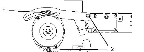
Illustration 1 g01075759
(1) Adjusting bolt
(2) Mounting bolts
1. Slightly loosen mounting bolts (2) and adjusting bolt (1).
2. Move the pulley in order to adjust the belt tension.
3. Tighten adjusting bolt (1) and mounting bolts (2). For the proper torque, refer to the Specifications Manual, SENR3130, "Torque Specifications".
4. Install the belt guard.
If new belts are installed, check the belt tension again after 30 minutes of engine operation at the rated rpm.
Water
Pump Belt
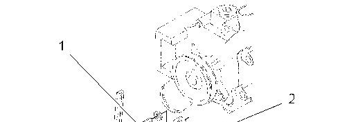
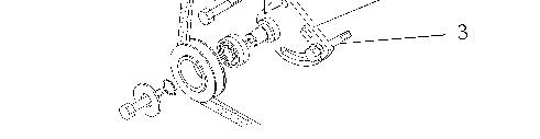
Illustration 2 g01075753
Exploded view of the drive assembly for a water pump belt
(1) Mounting bolt
(2) Square hole
(3) Adjusting bolt
1. Slightly loosen mounting bolts (1) and adjusting bolt (3).
2. Adjust the belt tension with a square drive in square hole (2).
3. Tighten adjusting bolt (3) and mounting bolt (1). For the proper torque, refer to the Specifications Manual, SENR3130, "Torque Specifications".
4. Install the belt guard.
If new belts are installed, check the belt tension after 30 minutes of engine operation at the rated rpm.
Copyright 1993 - 2024 Caterpillar Inc. All Rights Reserved. Private Network For SIS Licensees. Mon Feb 5 22:28:19 UTC+0530 2024
Product: MARINE ENGINE
Model: 3126 MARINE ENGINE 8NM
Configuration: 3126 Marine Engine 8NM00001-UP
Operation and Maintenance Manual 3116 and 3126 Marine Engines
Coolant - Change
SMCS - 1350-044; 1352; 1395-044; 1395
Refer to this Operation and Maintenance Manual, "Fluid Recommendations" for the correct intervals for changing the coolant.
Clean the cooling system and flush the cooling system before the recommended maintenance interval if the following conditions exist:
• The engine overheats frequently.
• Foaming is observed.
• The oil has entered the cooling system and the coolant is contaminated.
• The fuel has entered the cooling system and the coolant is contaminated.
Drain the Cooling System
Pressurized System: Hot coolant can cause serious burns. To open the cooling system filler cap, stop the engine and wait until the cooling system components are cool. Loosen the cooling system pressure cap slowly in order to relieve the pressure.
NOTICE
Care must be taken to ensure that fluids are contained during performance of inspection, maintenance, testing, adjusting, and repair
of the product. Be prepared to collect the fluid with suitable containers before opening any compartment or disassembling any component containing fluids.
Refer to Special Publication, NENG2500, "Cat Dealer Service Tool Catalog" or refer to Special Publication, PECJ0003, "Cat Shop Supplies and Tools Catalog" for tools and supplies suitable to collect and contain fluids on Cat products.
Dispose of all fluids according to local regulations and mandates.
1. Stop the engine and allow the engine to cool. Ensure that the engine will not start when the cooling system is drained.
2. Loosen the cooling system filler cap slowly in order to relieve any pressure. Remove the cooling system filler cap.
3. Open the cooling system drain valve (if equipped). If the cooling system is not equipped with a drain valve, remove one of the drain plugs.
Note: If equipped, be sure to drain the heater and any related supply and return lines.
Allow the coolant to drain.
NOTICE
Dispose of used engine coolant properly or recycle. Various methods have been proposed to reclaim used coolant for reuse in engine cooling systems. The full distillation procedure is the only method acceptable by Caterpillar to reclaim the used coolant.
For information regarding the disposal and the recycling of used coolant, consult your Cat dealer or consult Cat Dealer Service Tool Group:
Inside USA 1-800-542-TOOL
Inside Illinois 1-800-541-TOOL
Canada 1-800-523-TOOL
International 1-309-578-7372
Flush
Systems Filled with Cat ELC, Cat ELI, or a Conventional Coolant that Meets the Cat EC-1 Requirements and the Standards of ASTM D6210
1. Flush the cooling system with clean water in order to remove any debris.
2. Close the drain valve (if equipped). Clean the drain plugs. Install the drain plugs. Refer to the Specifications Manual, SENR3130, "Torque Specifications" for more information on the proper torques.
NOTICE
Fill the cooling system no faster than 19 L (5 US gal) per minute to avoid air locks.
3. Fill the cooling system with clean water. Install the cooling system filler cap.
4. Start and run the engine at low idle until the temperature reaches 49 to 66 °C (120 to 150 °F).
5. Stop the engine and allow the engine to cool. Loosen the cooling system filler cap slowly in order to relieve any pressure. Remove the cooling system filler cap. Open the drain valve (if equipped) or remove the cooling system drain plugs. Allow the water to drain. Flush the cooling system with clean water. Close the drain valve (if equipped). Clean the drain plugs. Install the drain plugs. Refer to the Specifications Manual, SENR3130, "Torque Specifications" for more information on the proper torques.
Systems Filled with Cat DEAC, Conventional Coolant which does not Meet the Cat EC-1 Requirements, or Supplemental Coolant Additive (SCA) and Water
3. Flush the cooling system with clean water in order to remove any debris.
4. Close the drain valve (if equipped). Clean the drain plugs. Install the drain plugs. Refer to the Specifications Manual, SENR3130, "Torque Specifications" for more information on the proper torques.
NOTICE
Fill the cooling system no faster than 19 L (5 US gal) per minute to avoid air locks.
5. Fill the cooling system with a mixture of clean water and Cat Fast Acting Cooling System Cleaner.
6. Choose 1 of the following options.
Add 0.5 L (1 pint) of cleaner per 15 L (4 US gal) of the cooling system capacity. For cooling systems with heavy deposits or plugging, add 0.5 L (1 pint) of cleaner per 3.8 to 7.6 L (1 to 2 US gal) of the cooling system capacity.
7. Install the cooling system filler cap.
8. Start and run the engine at low idle for a minimum of 30 minutes. For cooling systems with heavy deposits or plugging, run the engine for 90 minutes. The coolant temperature should be at least 82 °C (180 °F).
NOTICE
Improper or incomplete rinsing of the cooling system can result in damage to copper and other metal components.
To avoid damage to the cooling system, make sure to completely flush the cooling system with clear water. Continue to flush the system until all signs of the cleaning agent are gone.
9. Stop the engine and allow the engine to cool. Loosen the cooling system filler cap slowly in order to relieve any pressure. Remove the cooling system filler cap. Open the drain valve (if equipped) or remove the cooling system drain plugs. Allow the water to drain. Flush the cooling system with clean water. If equipped, be sure to flush the heater and any related supply and return lines. Close the drain valve (if equipped). Clean the drain plugs. Install the drain plugs. Refer to the Specifications Manual, SENR3130, "Torque Specifications" for more information on the proper torques.
Fill the Cooling System
NOTICE
Fill the cooling system no faster than 19 L (5 US gal) per minute to avoid air locks.
1. Fill the cooling system. Refer to this Operation and Maintenance Manual, "Fluid Recommendations" for more information on cooling system specifications Refer to this Operation and Maintenance Manual, "Refill Capacities" for information about the capacity of the cooling system. Do not install the cooling system filler cap.
2. Start and run the engine at low idle. Increase the engine rpm to high idle. Run the engine at high idle for 1 minute in order to purge the air from the cavities of the engine block. Stop the engine.
3. Check the coolant level. Maintain the coolant level within 13 mm (0.5 inch) below the bottom of the pipe for filling. Maintain the coolant level within 13 mm (0.5 inch) to the proper level on the sight glass (if equipped).
4. Clean the cooling system filler cap. Inspect the gasket that is on the cooling system filler cap. Only install the used filler cap if the gasket is not damaged. Use a 9S-8140 Pressurizing Pump to pressure test a reinstalled cooling system filler cap. The correct pressure for the cooling system filler cap is stamped on the face of the cooling system filler cap. If the
cooling system filler cap does not retain the correct pressure, install a new cooling system filler cap.
5. Start the engine. Inspect the cooling system for leaks and for proper operating temperature.
Copyright 1993 - 2024 Caterpillar Inc.
Rights Reserved.
Network For SIS Licensees. Mon Feb 5 22:28:43 UTC+0530 2024
Product: MARINE ENGINE
Model: 3126 MARINE ENGINE 8NM
Configuration: 3126 Marine Engine 8NM00001-UP
Operation and Maintenance Manual 3116 and 3126 Marine Engines
Coolant Extender (ELC) - Add
SMCS - 1352-544-NL
Note: Refer to this Operation and Maintenance Manual, "Fluid Recommendations" (Cooling System) for the maintenance interval for the addition of the coolant extender.
Cat ELC (Extended Life Coolant) and Cat ELI (Extended Life Inhibitor) do not require the frequent additions of any supplemental cooling additives. The Cat ELC Extender will only be added one time.
Note: Do not use conventional supplemental coolant additive (SCA) with Cat ELC or with Cat ELI.
Check the cooling system only when the engine is stopped and cool.
Personal injury can result from hot coolant, steam and alkali.
At operating temperature, engine coolant is hot and under pressure. The radiator and all lines to heaters or the engine contain hot coolant or steam. Any contact can cause severe burns.
Remove cooling system pressure cap slowly to relieve pressure only when engine is stopped and cooling system pressure cap is cool enough to touch with your bare hand.
Do not attempt to tighten hose connections when the coolant is hot, the hose can come off causing burns.
Cooling System Coolant Additive contains alkali. Avoid contact with skin and eyes.
i04862631
NOTICE
Care must be taken to ensure that fluids are contained during performance of inspection, maintenance, testing, adjusting, and repair of the product. Be prepared to collect the fluid with suitable containers before opening any compartment or disassembling any component containing fluids.
Refer to Special Publication, NENG2500, "Cat Dealer Service Tool Catalog" or refer to Special Publication, PECJ0003, "Cat Shop Supplies and Tools Catalog" for tools and supplies suitable to collect and contain fluids on Cat products.
Dispose of all fluids according to local regulations and mandates.
1. Loosen the cooling system filler cap slowly in order to relieve pressure. Remove the cooling system filler cap.
2. If necessary, drain enough coolant from the cooling system in order to add the Cat ELC Extender.
3. Add Cat ELC Extender according to the requirements for the cooling system capacity. Refer to this Operation and Maintenance Manual, "Refill Capacities" for the coolant capacity.
4. Clean the cooling system filler cap. Inspect the gaskets on the cooling system filler cap. Replace the cooling system filler cap if the gaskets are damaged. Install the cooling system filler cap.
For further information, refer to this Operation and Maintenance Manual, , "Fluid Recommendations".
Copyright 1993 - 2024 Caterpillar Inc. All Rights Reserved. Private Network For SIS Licensees.
Mon Feb 5 22:29:13 UTC+0530 2024
Product: MARINE ENGINE
Model: 3126 MARINE ENGINE 8NM
Configuration: 3126 Marine Engine 8NM00001-UP
Operation and Maintenance Manual
3116 and 3126 Marine Engines
Media Number -SEBU6164-10
Coolant Level - Check
SMCS - 1395-082
Check the coolant level when the engine is stopped and cool.
Updated -10/08/2018
Engines That Are Equipped with a Coolant Recovery Tank
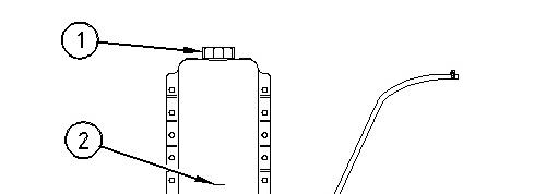
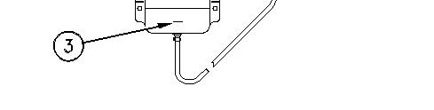
Illustration 1 g00103638
(1) Filler cap (2) "COLD FULL" mark (3) "LOW ADD" mark
1. Observe the coolant level in the coolant recovery tank. Maintain the coolant level to "COLD FULL" mark (2) on the coolant recovery tank.
i04550124
2. Loosen filler cap (1) slowly in order to relieve any pressure. Remove the filler cap.
3. Pour the proper coolant mixture into the tank. Refer to this Operation and Maintenance Manual, "Refill Capacities" for information about coolants. Do not fill the coolant recovery tank above "COLD FULL" mark (2).
4. Clean filler cap (1) and the receptacle. Reinstall the filler cap and inspect the cooling system for leaks.
Note: The coolant will expand as the coolant heats up during normal engine operation. The additional volume will be forced into the coolant recovery tank during engine operation. When the engine is stopped and cool, the coolant will return to the engine.
Engines That Are Not Equipped with a Coolant Recovery Tank
Pressurized System: Hot coolant can cause serious burns. To open the cooling system filler cap, stop the engine and wait until the cooling system components are cool. Loosen the cooling system pressure cap slowly in order to relieve the pressure.
1. Remove the cooling system filler cap slowly in order to relieve pressure.
2. Maintain the coolant level within 13 mm (0.5 inch) of the bottom of the filler pipe. If the engine is equipped with a sight glass, maintain the coolant level to the proper level in the sight glass.
3. Clean the cooling system filler cap and inspect the condition of the filler cap gaskets. Replace the cooling system filler cap if the filler cap gaskets are damaged. Reinstall the cooling system filler cap.
4. Inspect the cooling system for leaks.
1993 - 2024 Caterpillar Inc.
Product: MARINE ENGINE
Model: 3126 MARINE ENGINE 8NM
Configuration: 3126 Marine Engine 8NM00001-UP
Operation and Maintenance Manual 3116 and 3126 Marine Engines
Coolant Sample (Level 1) - Obtain
SMCS - 1350-008; 1395-554; 1395-008; 7542
Testing the engine coolant is important to ensure that the engine is protected from internal cavitation and corrosion. The analysis also tests the ability of the coolant to protect the engine from boiling and freezing. S·O·S Systems Coolant Analysis can be done at your Cat dealer. Cat S·O·S coolant analysis is the best way to monitor the condition of your coolant and your cooling system. S·O·S coolant analysis is a program that is based on periodic samples.
Note: Obtaining a Coolant Sample (Level 1) is optional if the cooling system is filled with one of the following coolants: Cat ELC (Extended Life Coolant)., Cat ELI (Extended Life Inhibitor) and Conventional Heavy-Duty Coolant.
Note: Obtain a Coolant Sample (Level 1) if the cooling system is filled with any of the following coolants: Cat DEAC, Cat SCA, and Conventional Heavy-Duty Coolants.
For additional information about coolant analysis and about other coolants, see this Operation and Maintenance Manual, "Fluid Recommendations" or consult your Cat dealer.
Sampling Conditions
If the engine is equipped with a sampling port, the engine should be running at operating temperature when the sample is obtained.
If the engine is not equipped with a sampling port, the coolant should be warm.
Use the following guidelines for proper sampling of the coolant:
• Complete the information on the label for the sampling bottle before you begin to take the samples.
• Keep the unused sampling bottles stored in plastic bags.
• Obtain coolant samples directly from the coolant sample port. You should not obtain the samples from any other location.
i08254010
• Keep the lids on empty sampling bottles until you are ready to collect the sample.
• Place the sample in the mailing tube immediately after obtaining the sample to avoid contamination.
• Never collect samples from expansion bottles.
• Never collect samples from the drain for a system.
Timing of the Sampling
Table 1
Recommended Interval
Type of Coolant
Cat DEAC
Cat SCA
Conventional Heavy-Duty Coolants
Cat ELC
Cat ELI
Commercial EC-1 Coolants
Level 1 Level 2
Every 250 hours Yearly(1)
Optional(1) Yearly(1)
(1) The Level 2 Coolant Analysis should be performed sooner if a problem is suspected or identified.
Note: Check the SCA (Supplemental Coolant Additive) of the conventional coolant at every oil change or at every 250 hours. Perform this check at the interval that occurs first.
Obtain the sample of the coolant as close as possible to the recommended sampling interval. To receive the full effect of S·O·S analysis, establish a consistent trend of data. To establish a pertinent history of data, perform consistent samplings that are evenly spaced. Supplies for collecting samples can be obtained from your Cat dealer.
NOTICE
Always use a designated pump for oil sampling, and use a separate designated pump for coolant sampling. Using the same pump for both types of samples may contaminate the samples that are being drawn. This contaminate may cause a false analysis and an incorrect interpretation that could lead to concerns by both dealers and customers.
Submit the sample for Level 1 analysis.
Note: Level 1 results may indicate a need for Level 2 Analysis. Copyright 1993 - 2024 Caterpillar Inc. All Rights Reserved.
This is the sample of the manual click on the download link for complete manual
DOWNLOAD LINK
For some reason if link does not work download this pdf and then click