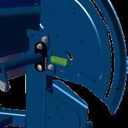
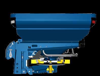
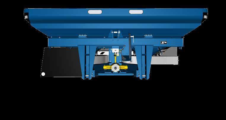
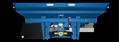
● Read Operator’s Manual and safety rules before starting.
● Read Operator’s Manual for the PTO shaft.
● Do not leave the tractor cabin without stopping the PTO system of the tractor!
● Turn off tractor engine and all electrical controlling devices during maintenance and other intervention on the spreader
● Ensure that bystanders maintain a sufficient safety distance from the spreader as long as the tractor engine is on.
● Do not enter the spreader when the tractor engine is on.
● Do not wear loosely fitting clothes that could become entangled with moving parts.
● Wear personal protective equipment when necessary or when required by the manufacturer of the fertiliser.
● Stay under the spreader is prohibited.
● Never go between spreader and tractor when engine is started.
● Never enter the spreader using the ladder when the spreader is not mounted to a tractor. The spreader might tilt over due to unstable weight distribution.
● Safety distance for flying material must be observed.
● Never go behind the spreader with rotating spreading discs.
● Avoid contact with rotating parts.
● Never put hand/object into the hopper with rotating spreading discs.
● Avoid contact as long as parts are moving.
● Never clean the spreader with rotating spreading discs.
● When parking the spreader ensure that the hopper is empty and the ground is solid and horizontal.
Read Operator’s Manual and safety rules before starting.
Never go under a raised spreader.
Never go between spreader and tractor when engine is started.
Never use the ladder when the spreader is not mounted on a tractor
Safety distance for flying material must be observed.
Never go behind the spreader with rotating spreading discs.
Avoid contact with rotating parts.
Never put hand/object into the hopper with rotating spreading discs.
Avoid contact as long as parts are moving.
Never clean the spreader with rotating spreading discs.
Do not spray water in this area.
Noise level measured inside a closed tractor cabin (level depends on tractor brand and model).
Lashing points for loading and unloading the spreader
Do not step on.
Not designed for boarding purposes.
Max. loading capacity. Do not exceed.
Type: Model No.: Serial number
Year: Manufacturing year
Liability
Liability
The operator is fully responsible for the setting of the spreader. The spreader must be set according to the fertiliser in use. Be aware that the fertiliser batch tested in the BOGBALLE A/S test facilities may differ from the fertiliser delivered to you even if with the same specifications.
BOGBALLE A/S cannot be held responsible for any kind of personal injury, crop damage, after effects etc.
Check list
Check list
Before every use
Check that the spreading discs turn easily
Check that the PTO shaft has the correct length
Check that the agitators turn easily
Check that the outlet shutters move easily
Check that the spreading vanes are intact and correctly mounted
Check that protection tubes of the PTO shaft are intact
Check that the security chain of the PTO shaft is fixed
Check that the top link and lift arms are intact and secured by lynch pin
Check that the tractor's lift arms are parallel
Check that ladders are placed in "swing-up position" - not conflicting with the fertilser spread
Especially for W-spreaders:
Check that the weight shows approx. 0 (+/- 3 kg) with an empty spreader
page
Before first time use See page
Cover the spreader with metal protective oil
After 5-8 hours
Retighten all nuts and bolts
After every use
Clean the spreader - make sure that all fertiliser and dust is removed
Cover the entire spreader with metal protective oil
Grease the agitator nipples with lubricating grease
page
page
Please also pay attention to the "Maintenance and Care" section on page 86
Check list
Before every use:
● Check that the spreading discs turn easily when the PTO shaft is not mounted.
NOTE: If not - check the transmission.
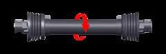
● Check that the PTO shaft has the correct length, with a correct overlap of the axle ends (min. 100 mm.) for the specific tractor (see figure 1)
If the overlap is too big or too small it will result in a serious damage of the complete transmission, including bending the splined input shaft of the transmission. Bending the splined input shaft will eventually cause breaking the input shaft of the transmission due to metal fatique.
● Check that the agitators turn with a similar resistance.
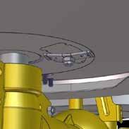
NOTE: If not - check the bearings and the distance between the joint and the hopper bottom (see figure 2)
● Check that the outlet shutters move easily.
NOTE: If not - check for dirt and jammed objects.
● Check that the spreading vanes are intact and correctly mounted.
NOTE: The vane is not intact if deformed or with wearing holes.
Rust on the surface of the vanes is OK as the fertiliser will grind of the rust.
● Protection tubes of the PTO shaft are intact.
● The security chain of the PTO shaft is fixed.
● Top link and lift arms are intact and secured by lynch pin.
● The lift arms of the tractor are set parallel.
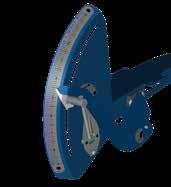
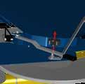
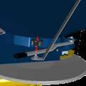
● Check that the bubble level is positioned correctly according to the fixed reference spirit level. Place the spreader horizontal and vertical leveled according to the reference spirit level – and check that the adjustable bubble level is correct adjusted at 0 degree (see figure 3 and 4)
● Especially for W-spreaders
Check that, with an empty and both horizontally and vertically levelled spreader, the weight shows approximately 0 kg in the display.
NOTE: If the weight is not 0 kg (+/- 3 kg) or fluctuates - see the CALIBRATOR or ISOBUS manual.
Check list
Before every use:
● Especially for hydraulic motor (80cc) L-line
The oil flow rate must be within the limits below:
Min: 45 l/min at minimum 140 bar
Max: 60 l/min at maximum 200 bar
NOTE: Oil filtration minimum 25 micron
● Especially for hydraulic motor (100cc) M-line
The oil flow rate must be within the limits below:
Min: 55 l/min at minimum 160 bar
Max: 75 l/min at maximum 210 bar
NOTE: Oil filtration minimum 25 micron
Before first time use:
(80 cc) L-line
(100 cc) M-line
● Before filling in fertiliser, cover the entire spreader with the metal protective oil delivered with the spreader. This will fill up and seal joints, preventing fertiliser dust getting into gaps (see figure 1)
● Especially for spreaders with CALIBRATOR
Before connecting electrical plugs in general – all connections must be protected by spraying contact spray on both male and female plugs. Let the liquid spray dry out before connecting the plugs (see figure 2)
Check that both ”+” and ”-” is connected directly to the tractor battery (see figure 3)
NOTE: If not - the weight will fluctuate several kg.
After 5-8 hours use:
● Retighten all nuts and bolts of the spreader (see page 86)
NOTE: The bolts in the central and angle gears are locked with lock-tite and do not need retightening. Stainless nuts + bolts may fuse together by removing and re-fitting. When re-fitting the thread must be greased with cutting lubricant graphite or copper grease.
Figure
Cleaning
After every use:
● Clean the spreader.
NOTE: Do not high-pressure clean directly on the seals of the transmission. Water will damage gears and bearings and will not be accepted as warranty (see figure 1)
● W-spreaders: Do not high pressure-clean the load cells and the bearings on the chassis.
● Cover the entire spreader with the metal protective oil delivered with the spreader or a similar oil.
● Clean and spray all plugs with contact spray. The contact spray will both grease and prevent moisture from corroding the connecting surface of the plugs. Do not use any other oil or grease for this purpose.
Cleaning the metal parts and afterwards protecting joints, edges and eventual damaged paintwork – by covering the spreader with metal protective oil - is extremely important.
Mineral fertiliser has high contents of corrosive components as for instance sulphur, which mixed with water, is converted into high corrosive acids – capable of corroding normal steel within hours. Even stainless steel might corrode without protection.
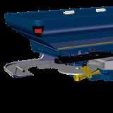
To ease the cleaning process – the M-line, L20 and L20W spreaders are provided with guide bars that can be opened during servicing and cleaning of the spreader (see figure 2)
The guide bars' lock is opened with a universal tool located behind the reflector panels - the bars can be swung from the inside out. Full access to the spreading mechanism is established easing the cleaning and oil protecting procedure.
NOTE: The guide bars must be completely fixed at the rear lock when closed after servicing.
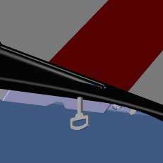
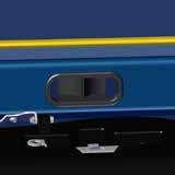
The rear light and reflector panels can be opened for cleaning and applying protection oil. To open the panels pull the the lock pin under the panels (see figure 3)
Do not high pressure clean the plugs for the lights!
The left panel holds a universal tool for opening the guide bars and screens, fitting the vanes and turning the hopper bottom.
NOTE: Closing the panel – the lock pin must be pulled and pushed into position when the panel is in place.
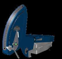
Cleaning deflectors are placed on the rear of the spreader (see figure 4)
By placing a water hose flushing on both sides of the V-deflectors, the spreader is cleaned on the inside and at areas with limited access.
Make sure that all areas are cleaned and that the fertiliser is not sticking to the surface of any metal component.
Figure 4
Figure 3
Figure 2
Check list
Useful hints
● The speed when driving on public roads must not exceed 30 km/h. The speed during spreading should not exceed 30 km/h.
● Prevent packing the fertiliser by driving long distances on uneven ground with a full hopper. If the fertiliser is packing in the bottom of the hopper, it might damage the agitator of the spreader.
● Do not let the spreading discs rotate long periods with the shutters closed. The fertiliser will compact and might cause blockage between shutter and agitator. The fingers of the agitator might be damaged and in worst case break.
● When spreading dusty fertiliser, it is necessary to clean the base of each side of the hopper regularly to prevent fine material to build up. Fine material can pack and might cause blockage between shutter and agitator. The fingers of the agitator might be damaged and in worst case break.
● The spreader should not be used without the pressure cone over the agitator
● Do not fill fertiliser into a wet hopper. The humidity will influence the flow of the fertiliser to the outlet.
● Be aware that the transmission has a gearing of 1:1,39. The number of PTO- rotations is not corresponding to the number of rotations on the spreading discs.
PTO = 540 rpm.
Spreading discs = 750 rpm.
● If the spreader leaks fertiliser, with the outlets closed, the distance between the joint and the hopper bottom is more than 0,5 mm. Adjust the joint to a distance of 0,2-0,5 mm (see figure 1).
● Make sure that the shutters close exactly in the middle of the V-mark at scale 0 (see figure 2) The distance between the shutters must be 0,5 mm.
Quick Guide - M60W, M45W, M35W, L20W, L15W with CALIBRATOR or ISOBUS
1 - Mounting
1.1 Mount the spreader in levelled position
1.2 Check that the PTO has a correct length to prevent damaging the transmission (For further information see page 10 and 58)
1.3 Remember to calibrate your speed input (see the CALIBRATOR’s manual)
2 - How to set the spreader
2.1 Standard working height: 75 cm from the upper link to the top of the crop (see figure 1) Special for L15W. Standard working height: 55 cm from upper link to top of the crop. For late application see chapter ’Spreader settings/Working height - late application’ page 60.
2.2 Find the relevant spread chart on www.bogballe.com or via the BOGBALLE Spread Chart app (see chapter ’Spread Charts’ page 21)
2.3 Make sure that the scale stop is fixed at scale 9 (see figure 2)
2.4 Make sure that Full Automatic Calibration (FAC) is activated (see the CALIBRATOR/ISOBUS Controller’s manual)
2.5 Check type of vanes according to spread chart
2.6 Set the position of the vanes according to spread chart
2.7 Set the tilt angle of the spreader according to spread chart (see figure 3) Special for L15W. Always horizontally levelled
3 - How to do headland spreading
3.1 Check that the spreader is in headland spreading mode (see chapter ’Normal and headland spreading’ page 45, 56 & 57) The same vane is used for both normal and headland spreading
3.2 Set the PTO speed according to the spread chart
4 - How to do normal spreading
4.1 Check that the spreader is in normal spreading mode (see chapter ’Normal and headland spreading’ page 45, 56 & 57)
4.2 Set the PTO speed according to the spread chart
Quick Guide - M45, M35, L20, L15 with CALIBRATOR
1 - Mounting
1.1 Mount the spreader in levelled position
1.2 Check that the PTO has a correct length to prevent damaging the transmission (For further information see page 10 and 58)
1.3 Remember to calibrate your speed input (see the CALIBRATOR’s manual)
2 - How to set the spreader
2.1 Standard working height: 75 cm from the upper link to the top of the crop (see figure 1) Special for L15. Standard working height: 55 cm from upper link to top of the crop For late application see chapter ’Spreader settings/Working height - late application’ page 60.
2.2 Find the relevant spread chart on www.bogballe.com or via the BOGBALLE Spread Chart app (see chapter ’Spread Charts’ page 21)
2.3 Make sure that the scale stop is fixed at scale 9 (see figure 2)
2.4 Carry out a calibration for quantity setting
2.5 Check type of vanes according to spread chart
2.6 Set the position of the vanes according to spread chart
2.7 Set the tilt angle of the spreader according to spread chart (see figure 3) Special for L15. Always horizontally levelled (see figure 4)
3 - How to do headland spreading
3.1 Check that the spreader is in headland spreading mode (see chapter ’Normal and headland spreading’ page 45, 56 & 57) The same vane is used for both normal and headland spreading
3.2 Set the PTO speed according to the spread chart
4 - How to do normal spreading
4.1 Check that the spreader is in normal spreading mode (see chapter ’Normal and headland spreading’ page 45, 56 & 57)
4.2 Set the PTO speed according to the spread chart
Quick Guide - M45, M35, L20, L15 with mechanical control
1 - Mounting
1.1 Mount the spreader in levelled position
1.2 Check that the PTO has a correct length to prevent damaging the transmission. (For further information see page 10 and 58)
2 - How to set the spreader
2.1 Standard working height: 75 cm from the upper link to the top of the crop (see figure 1) Special for L15. Standard working height: 55 cm from upper link to top of the crop (see page 60 figure 2) For late application see chapter ’Spreader settings/Working height - late application’ page 60.
2.2 Find the relevant spread chart on www.bogballe.com or via the BOGBALLE Spread Chart app (see chapter ’Spread Charts’ page 21)
2.3 Carry out a calibration for quantity setting (see page 22)
2.4 Fix the scale stop according to the FlowFactor
2.5 Check type of vanes according to spread chart
2.6 Set the position of the vanes according to spread chart
2.7 Set the tilt angle of the spreader according to spread chart (see figure 2) Special for L15. Always horizontally levelled (see figure 3)
Quick Guide - M45, M35, L20, L15 with mechanical control
3 - How to do headland spreading
3.1 Check that the spreader is in headland spreading mode (see chapter ’Normal and headland spreading’ page 45, 56 & 57) The same vane is used for both normal and headland spreading
3.2 Set the PTO speed according to the spread chart
3.3 Start spreading and make sure you keep a constant forward and PTO speed
4 - How to do normal spreading
4.1 Check that the spreader is in normal spreading mode (see chapter ’Normal and headland spreading’ page 45, 56 & 57)
4.2 Set the PTO speed according to the spread chart
4.3 Start spreading and make sure you keep a constant forward and PTO speed
Principle sketch
Top link fixture and spirit level
Setting pointer
Degree meter
Link pins
Angle transmission
Shutters
Connection rod
Friction clutch
Setting axle
Serial no. plate
Principle sketch
Top link fixture
Setting pointer
Degree meter
Link pins
Angle transmission
Shutters
Connection rod
Friction clutch
Setting axle
Serial no. plate
Spread charts
How to use
Spread charts are available on www.bogballe.com or from the Bogballe Spread Chart App (see figure 1)
Example
Spreader settings
Calibration value Kg/30 sec
Scale
Outlet position
Tilt angle
Vane type
Vane positions
Normal (rpm)
TREND Headland (rpm)
DYNAMIC Headland (rpm)
Vane types
Tab for Analysis
Tilt angle (see figure 2)
Tab to open full spread chart
Calibration and quantity setting
Basic principle and definition of standard calibration set point value STD
All spreaders are equipped with identical standard outlets (STD with flow-rate <300 kg/min) which must always be used for calibration. Depending on model type, the L-line and M-line spreaders additionally can be set to different other flow-outlet positions. For further information please see table below (For M-line please also see figure 1. For L-line please also see figure 2, 3 and 4)
Definition of calibration set point value:
The calibration value is always based on the quantity of material flowing from one side of the spreader by use of the STD outlet:
• with shutters open for 30 seconds and scale pointer open at 4,5
The above definition based on the flow from the STD flow-outlet position is always used as the set point value for all other settings in quantity and flow.
Flow-outlet positions and flow-rates
Outlet Position Quantity
Outlet closed 0 kg/min
Most common quantities and for calibration
High quantities
Extreme high quantities
Low quantity
Micro granular/small seeds
* STD outlet used for calibration (see figure 1+2) ** Optional equipment by use of reduction inserts (see figure 3+4)
<300 kg/min*
<450 kg/min
<650 kg/min
<75 kg/min
<15 kg/min
1
2
3
Figure
L15(W)
Figure 4
L15(W)
Figure
Figure
Calibration and quantity setting
M60W, M45W, M35W, M45, M35, L20W, L20
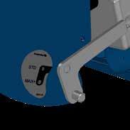
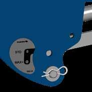
The spreaders are equipped with a hopper bottom that can be turned 360° with different flow-outlets for achieving high/low flow rates. The turnable hopper bottom is positioned underneath each side of the hopper outlet and each position is used for optimizing the precision and accuracy of the quantity applied (M-line example see figure 1)
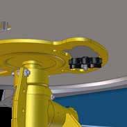
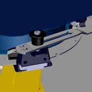
The position of the hopper bottom must be set manually by the operator. Release the locking pawl and turn the hopper bottom to the desired position. The different positions are marked with signatures as defined below (see figure 1+2) A universal tool for setting the outlet position is located in the rear light/reflector panel (M-line example see figure 3+4) or at the back of the spreader (L-line). It must be the same outlet position on both sides.
Note: The calibration value is based on the selected outlet position, e.g. STD or MAX. To ensure correct flow, the outlet position on spreader and Calibrator must be set identical. When a table is defined, it must also be noted which bottom outlet is selected on the machine.
For further information regaring how to make optimum use of each flow-outlet position, please see next page.
L15W, L15
In the standard spreader only STD outlet position is available. MIC and MIN inserts are available as optional equipment.
Figure
Calibration and quantity setting
Correct Flow-outlet setting at high/low rates
position Outlet closed*
position
position
setting
position
position
Standard outlet for most common quantities
Maximum outlet for high quantities (only M-line)
Maximum Plus for extremely high quantities (only M-line)
Minimum outlet for low quantities**
Kg/min
Kg/min
Kg/min
Kg/min
Micro outlet for micro granular** Kg/min
*L15: Only possible on right side
**L15(W): Optional equipment by use of reduction inserts
The flow in [Kg/min] appear from the spread chart of the actual fertiliser and the quantity varies depending on the type implicit shape, size, surface and density of the fertiliser grains.
1) STD position is recommended in general and covers the most common fertilisers and quantities.
2-3) MAX and MAX+ positions are used in case the STD position exceeds its quantity limits, by the scale pointer reaching scale 9.0 – Full open. (only possible on M-line)
3) MAX+ setting is a combination of the MAX – outlet position and an additional MAX+ connection rod, connecting the scale pointer and the outlet shutters of the spreader, gearing up the degree of movement/flow. MAX+ setting is achieved by moving the rod connection. (Only possible on M-line) (see
4) MIN position is used in case the STD position requires a scale pointer position less than 2.0 – which is the minimum position for achieving an optimal and constant flow of the fertiliser. (L15(W): Optional equipment by use of reduction inserts)
5) MIC position is for micro granular e.g small seeds and slug pellets. This outlet position is only for operating with the scale pointer at fixed position (Fix Scale) together with a fixed and constant forward speed. (L15(W): Optional equipment by use of reduction inserts)
With the outlet in STD position as set point value - the difference in flow for the respective settings on the Flow-outlet position is defined by the following factors:
Flow-outlet position
Quantity factor for Calibration value
position equals STD value
position equals (only M-line)
setting equals (only M-line)
position* equals
* L15(W): Optional equipment by use of reduction inserts
STD value
STD value
STD value
position* equals FIX-scale setting
The STD calibration value is defined by either:
● Spread chart value (See spread chart "Calibration value")
The easiest procedure – recommended for W-models
● S-indicator value
A quick and easy procedure – recommended for all models
● Manual calibration on spreader
Calibration and quantity setting
MW-line, L20W, L15W with CALIBRATOR or ISOBUS, fully automatic calibration (FAC)
Note: The display illustrations is based on the CALIBRATOR TOTZ display. The ISOBUS display and the functionality is basic identical, but the layout and design might differ slightly
MW-line and LW-line spreaders equipped with weighing technique is fully automatically calibrated (FAC) during spreading in the field. The system automatically adjusts the scale pointer and the shutters according to the requested quantity,
To optimize the accuracy in quantity, when changing from one type of fertiliser to another, it is recommended to enter the actual STD calibration value for the specific type of fertiliser. This procedure ensures the best possible accuracy and the full automatic calibration is activated after spreading only 25 kg.
Activation of fully automatic calibration
The fully automatic calibration is activated either by pushing and holding the calibration button for three seconds –or by choosing “Full Auto Calib, FAC” at the Calibration MENU. FAC is predefined when turning on the CALIBRATOR TOTZ (see figure 1)
When switched on the full automatic calibration is indicated by a flashing “W” icon in the display (see figure 2 and 3)
The STD calibration value is considered as the set point value for every other setting in quantity and flow The CALIBRATOR TOTZ, when set to control the actual spreader model – will automatically adjust the “Quantity factor for calibration value” when setting and entering the set point value based on the STD value.
STD calibration value is the starting point. At the other outlet positions, a factor is calculated in the Calibrator automatically.
CALIBRATOR TOTZ button
Figure 2
Calibration and quantity setting
M-line, L20W, L20 & CALIBRATOR / use of calibration value STD
The STD calibration value is entered by pressing the Calibration button (see figure 1) and entering the STD value, known from the actual spread chart or from earlier experience.
Entering a STD calibration value via the Calibration button:
Calibration Menu
Flow-outlet setting (STD)*
Set STD calibration value
The STD calibration value is defined and marked "STD" at the top of the screen (see figure 2)
* In L20, L20W, L15, L15W configuration only STD, MIN, MIC is displayed.
* L15W. Position MIN and MIC by use of optional equipment.
Figure 1
CALIBRATOR TOTZ button
2 CALIBRATOR TOTZ display
Figure
Calibration and quantity setting
M-line & CALIBRATOR / use of calibration value STD in MAX flow-outlet position
In case the turnable hopper bottom is set in one of the other flow-outlet positions, the calibration value can be compensated by pushing the Calibration button once again - defining the actual hopper bottom position - without entering a new value. The calibration value is then automatically compensated.
Menu
Flow-outlet pos.
Calibration Menu
Flow-outlet setting (MAX)
Set MAX calibration value (STD value x 1,4)
The MAX calibration value is defined and marked "MAX" at the top of the screen (see figure 1)
In case a MAX, MAX+ or MIN calibration value is known, the actual calibration value can be directly entered after choosing the Flow-outlet setting B) - by entering the known calibration value C)
Before spreading always check that:
The setting in CALIBRATOR and flow outlet position are identical.
Note: The position of the turnable hopper bottom must be set manually by operator (see page 22).
Calibration and quantity setting
M-line & CALIBRATOR / use of STD calibration value via the touch display
Example of setting and entering the STD calibration value transferred to the Flow-outlet in MAX–position by use of finger touch display (see figure 1):
The Flow-outlet position / CALIBRATOR actual setting is defined above with the actual calibration value. In this example “MAX”.
This procedure can also be performed by pressing Input and selecting the calibration value. (see figure 2)
Note: The position of the turnable hopper bottom must be set manually by operator. (see page 22)
Figure 1
TOTZ button
TOTZ button
Calibration and quantity setting
M-line, L-line & CALIBRATOR, micro granular / small seeds with fixed scale
The position of the hopper bottom can also be defined via MENU and Outlet Position. This gives further access to define MIC – position for spreading micro granular and small seeds, which automatically leads to “Fixed Scale” setting.
Outlet Position
MIC Flow-outlet setting = Fix-scale setting*.
Fixed Scale definition
* In L20, L20W, L15, L15W configuration only STD, MIN, MIC is displayed.
The Scale pointer setting must be set according to the spread chart, valid for the actual media at a defined fixed forward speed.
NOTE: Do not use the full automatic calibration (FAC) when spreading small seeds, slug pellets etc.
Calibration and quantity setting
M-line manual calibration on spreader MC
This procedure is more time consuming compared to entering the calibration value defined at the spread chart or tested by the S-indicator.
The manual calibration is completed by:
● Filling in minimum 200 Kg of fertiliser into a clean and dry the hopper
● Remove the Calibration-plate at one of the two spreading discs (see figure 1)
● Move the SC Dynamic in position for calibrating and emptying the hopper (Only spreaders without SC Dynamic actuators) (see figure 2)
● Turn the Calibration-hole in the disc directly underneath the outlet of the hopper (see figure 3)
● Place a bucket (min 30 l) underneath the hole in the disc (see figure 4)
● Turn the hopper bottom in position “OFF” on the opposite side of the hopper (see figure 5)
● Set the CALIBRATOR into calibration mode by pressing calibration button (see figure 6)
Figure 6
CALIBRATOR TOTZ button
Figure 2
Figure 1
Figure 3
Figure 4
Figure 5
Calibration and quantity setting
M-line
manual calibration on spreader
Press the Calibration button – and choose Manual Calib MC.
Choose and ENTER “Manual Calib MC”
Confirm Manual Calib for 30 seconds by ENTER
The scale pointer / outlet opens automatically at scale 4,5 for 30 seconds and closes again. Weigh the contents of the bucket (Remember to tare the scale) – only the contents must be entered as Calibration value.
Flow-outlet setting (STD)
INPUT (Confirm all inputs) - By selecting "Confirm all inputs"
IMPORTANT: If the Manual calibration is not carried out with the hopper bottom plate in STD position, the measured calibration value must be compensated / corrected and entered according to the:
“Quantity factor for Calibration value”
Example: Manual calibration value at MAX position 35,00 Kg Compensation (35,00 / 1,4) = STD calibration value 25,00 Kg
● Reinstall the Calibration-plate and put the SC Dynamic shutter back in position. remember to turn flow plate on the opposite side back in position(Only spreaders without SC Dynamic actuators).
Note: Do not start pto - when calibrating or emptying the hopper.
Calibration and quantity setting
M-line, L-line & CALIBRATOR, quick setting via spread chart value
Press the Calibration button – and choose Spread chart.
Please see page 21 defining setting according to the spread chart.
Choose and ENTER “Spread chart”
Set the actual STD calibration value
Flow-outlet setting (STD)
INPUT (Confirm all inputs)
Calibration and quantity setting
M45, M35, L20 & CALIBRATOR by use of S-indicator value
The S-indicator is an easy and uncomplicated way to determine the STD Calibration value.
Please follow the instruction supplied with the S-indicator.
Note: The fertiliser´s condition can vary each delivery. It is advised to carry out a new calibration for each delivery/batch.
It is recommended to carry out three consecutive S-indicator tests and middle the sum with the number of tests into an average value.
The sample must be representative and carefully selected from the middle / center of the bulk / bag.
Make sure that the S-indicator is vertical positioned and that the inner side of the tarpaulin / cone is absolutely clean and dry.
● Fill the S-indicator with mineral fertiliser
● Open the shutter and close after precisely 30 seconds. The timing is essential.
● Weigh the fertiliser collected within an accuracy of +/- 50 gram.
Calibration and quantity setting
Press the Calibration button – and choose S-indicator:
Choose and ENTER “S-indicator”
Set the actual middle / average S-indicator value – and ENTER the value.
Set and define the Flow-outlet setting* S-indicator
INPUT (Confirm all inputs)
*In L20(W) and L15(W) configuration only STD, MIN, MIC is displayed.
The calculation from S-indicator value to any of the other Flow-outlet position is automatically accomplished by the CALIBRATOR.
The S-indicator value corresponds to the various Flow-outlet settings as follows:
Flow-outlet position
Quantity factor for S-indicator value position equals S-indicator value position equals S-indicator value setting equals S-indicator value position equals S-indicator value position equals FIX-scale setting
* Only possible on M-line / ** L15(W): Optional equipment by use of reduction inserts
Calibration and quantity setting
M45, M35, L20, L15 & CALIBRATOR ICON by use of S-indicator value
The S-indicator is an easy and uncomplicated way to determine the STD Calibration value.
Please follow the instruction supplied with the S-indicator.
Note: The fertiliser´s condition can vary each delivery. It is advised to carry out a new calibration for each delivery/batch.
It is recommended to carry out three consecutive S-indicator tests and middle the sum with the number of tests into an average value.
The sample must be representative and carefully selected from the middle / center of the bulk / bag.
Make sure that the S-indicator is vertical positioned and that the inner side of the tarpaulin / cone is absolutely clean and dry.
● Fill the S-indicator with mineral fertiliser
● Open the shutter and close after precisely 30 seconds. The timing is essential.
● Weigh the fertiliser collected within an accuracy of +/- 50 gram.
Calibration and quantity setting
The S-indicator value corresponds to the various Flow-outlet settings as follows:
Flow-outlet position
Quantity factor for S-indicator value
position equals S-indicator value
position equals S-indicator value
setting equals S-indicator value
position equals S-indicator value
position equals FIX-scale setting
* Only possible on M-line / ** L15: Optional equipment by use of reduction inserts
Calculate the S-indicator value by use of above table. Press menu botton on CALIBRATOR ICON and select calibration pictogram and enter the calculated calibration value (see figure 1 and 2)
Example:
Setting the Flow-outlet in STD position – the S-indicator value must be multiplied with a factor of 6,65. (S-indicator value 3,383 Kg (3,383 x 6,65) = 22,5 Kg = Calibration value at STD position). Enter the value in CALIBRATOR ICON (see figure 1 and 2)
The compensated calibration value must be entered corresponding to flow-outlet.
Calibration and quantity setting
M45, M35 & CALIBRATOR ICON setting according to flow-outlet position
The M-line spreader is identical with the MW-line spreader – except for the weighing system and the Full Automatic Calibration. All other features on the M-line are identical with the MW-line and calibrating the M-line refers to MW instructions on the previous pages.
M45, M35 with CALIBRATOR ICON
Equipped with CALIBRATOR ICON the spreader is operated according to the instruction book of the CALIBRATOR ICON.
To make use of the M-line hopper bottom position MAX and MIN, the STD calibration value must manually be compensated and recalculated as the Flow-outlet position affects the Calibration value, defined by the following factors:
Flow-outlet position
Quantity factor for Calibration value position equals STD value position equals
value setting* equals STD value position equals STD value position equals FIX-scale setting
* MAX+ is not possible with CALIBRATOR ICON
Spread chart value
Please see page 21 defining setting according to the spread chart.
Example:
Setting the Flow-outlet in MAX position – the STD calibration value must be multiplied with a factor of 1,4. (STD value 22,50 Kg (22,5 x 1,4) = 31,50 Kg = Calibration value at MAX position)
The compensated calibration value must be entered corresponding to the position of the hopper bottom position.
NOTE: The calibration value must always correspond to the Flow-outlet of the hopper bottom position and the position of the hopper bottom must be set manually by operator.
Calibration and quantity setting
S-indicator value
The S-indicator is an easy and uncomplicated way to determine the STD Calibration value. Please follow the instruction that comes with the S-indicator. Please note that the fertiliser´s condition can vary each delivery. It is advised to carry out a new calibration for each delivery/batch.
It is recommended to carry out three consecutive S-indicator tests and middle the sum with the number of tests into an average value.
The sample must be representative and carefully selected from the middle / center of the bulk / bag.
Make sure that the S-indicator is vertical positioned and that the inner side of the tarpaulin / cone is absolutely clean and dry.
● Fill the S-indicator with mineral fertiliser
● Open the shutter and close after precisely 30 seconds. The timing is essential.
● Weigh the fertiliser collected within an accuracy of +/- 50 gram. It is recommended to repeat the process to verify the accuracy.
The S-indicator value corresponds to the various Flow-outlet settings as follows:
Flow-outlet position
Quantity factor for S-indicator value
position equals S-indicator value position equals S-indicator value
position equals S-indicator value
position equals FIX-scale setting
Example:
Setting the Flow-outlet in MAX position – the S-indicator value must be multiplied with a factor of 9,45. (S-indicator value 3,333 Kg (3,333 x 9,45) = 31,50 Kg = Calibration value at MAX position)
The compensated calibration value must be entered corresponding to the position of the turnable hopper bottom.
NOTE: The calibration value must always correspond to the setting of the turnable hopper bottom. The position of the turnable hopper bottom must be set manually by operator.
Calibration and quantity setting
L20, L15 & CALIBRATOR ICON setting according to flow-outlet position
Equipped with CALIBRATOR ICON the spreader is operated according to the instruction book of the CALIBRATOR ICON.
To make use of the optional equipment for achieving MIN flow rates, the STD calibration value must manually be compensated and recalculated as the Flow-outlet affects the Calibration value, defined by the following factors:
Flow-outlet position
*
Quantity factor for Calibration value
position equals STD value
position equals STD value
position equals FIX-scale setting
Spread chart value
Please see page 21 defining setting according to the spread chart.
Example:
by use of reduction insert MIN the STD calibration value must be multiplied with a factor of 0,35. (STD value 22,50 Kg (22,5 x 0,35) = 7,90 Kg = Calibration value
The compensated calibration value must be entered directly in CALIBRATOR ICON..
NOTE: The calibration value must always correspond to the Flow-outlet of the hopper bottom.
*Using MIC outlet and FIX-scale with CALIBRATOR, please see page 30. On spreaders with CALIBRATOR ICON tighten scale stop according to spread charts and start/stop spreading as usual. Confirm error code 10 by pressing Enter.
Calibration and quantity setting
S-indicator value L15 and L20 with CALIBRATOR ICON
The S-indicator is an easy and uncomplicated way to determine the STD Calibration value. Please follow the instruction that comes with the S-indicator.
Please note that the fertiliser´s condition can vary each delivery. It is advised to carry out a new calibration for each delivery/batch.
It is recommended to carry out three consecutive S-indicator tests and middle the sum with the number of tests into an average value.
The sample must be representative and carefully selected from the middle / center of the bulk / bag.
Make sure that the S-indicator is vertical positioned and that the inner side of the tarpaulin / cone is absolutely clean and dry.
● Fill the S-indicator with mineral fertiliser
● Open the shutter and close after precisely 30 seconds. The timing is essential.
● Weigh the fertiliser collected within an accuracy of +/- 50 gram. It is recommended to repeat the process to verify the accuracy.
The S-indicator value corresponds to the various Flow-outlet settings as follows:
Flow-outlet position
Quantity factor for S-indicator value
position equals S-indicator value
position equals S-indicator value
position equals FIX-scale setting
Example:
Setting the Flow-outlet in MIN position – the S-indicator value must be multiplied with a factor of 2,25. (S-indicator value 3,333 Kg (3,333 x 2,25) = 7,50 Kg = Calibration value at MIN position)
The compensated calibration value must be entered in CALIBRATOR ICON.
NOTE: The calibration value must always correspond to the setting of the flow outlet of the hopper bottom.
Calibration and quantity setting
M45, M35, L20, L15 calibration with S-Indicator in combination with hydraulic control
Please notice that the fertiliser’s condition can vary from each delivery. It is advised to carry out a new calibration for each delivery/batch.
It is recommended to carry out three consecutive S-indicator tests and middle the sum with the number of tests into an average value.
The sample must be representative and carefully selected from the middle / center of the bulk / bag.
Make sure that the S-indicator is vertical positioned and that the inner side of the tarpaulin / cone is absolutely clean and dry.
● Fill the S-indicator with mineral fertiliser
● Open the shutter and close after precisely 30 seconds. The timing is essential.
● Weigh the fertiliser collected within an accuracy of +/- 50 gram. It is recommended to repeat the process to verify the accuracy.
● Calculate the Flow Factor according to the formula below (see figure 2)
= Quantity
= Working Width
= Speed
= Amount of fertiliser in grams
= Calculation factor
● Adjust the scale stop according to the Flow Factor.
Example, STD Outlet setting calculation factor 155
[Kg/Ha] x [M] x [Km/h] x 155
Figure 1
Calibration and quantity setting
M45, M35
Flow-outlet position
Measured kg Calculation factor [XXX] position
S-indicator value position
L20, L15
S-indicator value position
position
position
Flow-outlet position
S-indicator value
S-indicator value
Fix Scale according to spread chart
Measured kg Calculation factor [XXX] position
S-indicator value position*
S-indicator value position*
Fix Scale according to spread chart
*L15: Optional equipment by use of reduction inserts
Rest-emptying
M-line + L20(W)
Remaining fertiliser in the hopper must be unloaded / drained, by opening the shutters following the procedure below:
● Remove the Calibration-plate at spreading discs (see figure 1)
● Position the SC Dynamic in position for calibrating and emtying the hopper (Only M-line spreaders without SC Dynamic actuators) (see figure 2).
● Position the calibration-hole in the disc directly underneath the outlet of the hopper (see figure 3)
● Place a bucket underneath the hole in the disc (see figure 4)
Note: Do not rotate the spreading discs by starting the pto - when calibrating or emptying the hopper. Open the shutters fully - until the hopper is empty and insert the calibration plate(s).
L15(W)
Remaining fertiliser in the hopper must be unloaded / drained, by opening the shutters following the procedure below:
● Use the universal tool to remove the Calibration-plate at spreading discs (see figure 5)
● Place a bucket underneath the hole in the disc (see figure 4)
Note: Do not rotate the spreading discs by starting the pto - when calibrating or emptying the hopper. Open the shutters fully - until the hopper is empty and insert the calibration plate(s).
When using a CALIBRATOR
By pressing OPEN the shutters opens fully to scale 9.0. The open function is positioned right above the Menu button. (see figure 6). For Isobus spreader select Menu/Settings/Cleaning
Normal and headland spreading
In general
Bogballe offers two systems for headland spreading depending on model type and configuration:
• Trend Headland (recommended from 12-24 metres / standard on L-line and M-line)
• Dynamic Headland (recommended from 27-42 metres / only M-line)
Trend Headland
The rotation direction of the spreading discs determines the mode of spreading. For normal spreading the discs must rotate towards each other (in-centre) (see figure 1). For spreading To Border or From Border the discs rotate away from each other (off-centre) (see figure 2). The border must always be on the right side in driving direction.
Dynamic Headland
For spreaders equipped with Section Control Dynamic and working widths from 27-42 metres. It is recommended to use Dynamic Headland mode for border spreading from27-42 metres. With Dynamic Headland, both the left and the right side can be selected as the field border. In this mode, the spreading discs rotate with normal spreading direction. (see figure 3). Dynamic Headland is standard on M45W and M60W. For more information about Dynamic Headland functionality see also page 56-57.
To Border (Trend Headland)
To Border spreading can be divided into three categories:
Minimum: The amount of fertiliser outside field border is 3 ‰ or less of the total kg/ha on 100 metres distance. Environmentally optimised spreading (EOS) according to EN13739-1.
Recommened rate reduction: -20%
Medium: The amount of fertiliser at the border is between 25 -70 % of the kg/ha of fertiliser in the normalspread area.
Recommened rate reduction: -10%
Maximum: The amount of fertiliser to the border is close to 100% of the kg/ha. Yield optimised spreading (YOS) according to EN13739-1.
Recommened rate reduction: 0%
NOTE: For YOS at large working widths +36 M it is advised to stay in the mode for normal spreading. The nature of the spread pattern results in the optimum distribution when spreading to border.
NOTE: The recommended PTO speed given in the spread charts for headland spreading corresponds to the Minimum category characterised by EOS.
By changing the PTO speed it is possible to respectively increase or decrease the spread width to the border (see figure 3)
+ 50 rpm = + 1-2 metres full amount closer to the border - 50 rpm = - 1-2 metres full amount further away from the border
Normal and headland spreading
From Border
The From Border spreading system is developed for working widths from 12 – 36 metres. In case working widths larger than 36 metres are required – the To Border spreading system must be used.
On working widths 12 - 21 metres it is necessary to lower the PTO speed when spreading in the 2nd tramline (see figure 1) For PTO speed see table below.
Normal and headland spreading
Settings for M60W, M45W, M35W, L20W, L15W in Trend Headland Mode - To Border
Change the rotation direction of the discs to switch between normal and headland spreading.
spreading
NOTE: STOP the PTO when switching.
Headland spreading in Trend Headland Mode
Spreading Mode Trend Headland via electrical remote control (Calibrator or Isobus)
Press the Headland spreading icon to select spreading mode (see figure 1). Please note that remote controlled Trend Headland spreading is optional equipment on M45W, M60W, L20W and L15W.
1. Normal spreading
When set to normal spreading mode, the headland spreading icon in the diplay is shown as a switched off/greyed out icon. (see figure 2).
2. Headland spreading To Border
When the headland function is activated, the headland spreading icon is displayed on the screen (see figure 3) For more detailed instructions see also the CALIBRATOR or the ISOBUS controller manual.
Spreading mode Trend Headland manually operated
The function is operated via handle on back of the spreader.
1. Normal spreading
Set the handle in inner position for normal spreading. (see figure 4)
2. Headland spreading To Border
Pull out the handle for Headland spreading. (see figure 4)
Headland spreading in general
During headland spreading, the field border must always be on the right side of the spreader in driving direction. Check the recommended PTO speed in the spread chart.
Settings for M60W, M45W, M35W, L20W, L15W, Trend Headland Mode - From Border
Manual shift L20W, M45W and M60W (optional).
On the back of the spreader - Set the handle in outer position (see figure 1)
From Border manually operated is standard on L15(W) For operation of From Border on L15(W), please see page 54.
From border spreading (Optional)
Electrical remote shift
CALIBRATOR: Set to From Border. The spread icon on the diplay is shown with a green From Border icon (see figure 2)
ISOBUS: Set to From Border under Trend Headland (see figure 3), then headland symbol From Border must be visible in the display (see figure 2)
Normal and headland spreading
Settings
for
M45, M35, L20, L15 in Headland Mode - Trend Headland
Change the rotation direction of the discs to switch between normal and headland spreading.
Normal spreading
NOTE: STOP the PTO when switching.
Normal spreading
Electrical remote shift
CALIBRATOR: Set to Normal. The headland symbol must not be visible in the display (see figure 1). For detailed instructions see the CALIBRATOR manual.
Cable remote shift
Move the handle away from the cable (see figure 2)
Manual shift
On the back of the spreader - Set the handle in inner position (see figure 3)
Headland spreading
The border must always be on the right side of the spreader in driving direction.
To border spreading
Electrical remote shift
CALIBRATOR: Set to "To Border". Headland symbol must be visible in the display (see figure 4). For detailed instructions see the CALIBRATOR manual.
Cable remote shift
Move the handle towards the cable (see figure 2).
Manual shift
On the back of the spreader - Set the handle in outer position (see figure 3)
Headland spreading in Trend Headland Mode
Normal and headland spreading
Settings for M45, M35, L20
From border spreading (Option)
Electrical remote shift
Set to From Border. Headland symbol must be visible in the display (see figure 1) For detailed instructions see the CALIBRATOR manual.
Cable remote shift
Move the handle towards the cable (see figure 2)
Manual shift
On the back of the spreader - Set the handle in outer position (see figure 3)
Figure
Headland symbol
Normal and headland spreading
Settings for M45, M35, L20
To/From border spreading with cable remote
Cable remote shift
Normal spreading
● Move both handles away from the cables (see figure 1)
To Border spreading
Move right handle away from the cable and move left handle towards the cable (see figure 2)
From Border spreading
Move both handles towards the cables (see figure 3)
Figure
Normal and headland spreading
Settings for M45, M35, L20
To/From border spreading with manual shift
Manual shift
On the back of the spreader
To Border spreading
Move left handle in inner position, right handle in outer position (see figure 1)
Normal spreading
Move both handles in inner position (see figure 1)
From Border spreading
Move both handles in outer position (see figure 2)
Figure
Normal and headland spreading
Settings for L15(W) in Headland Mode - Trend Headland
Change the rotation direction of the discs to switch between normal and headland spreading.
Normal spreading
NOTE: STOP the PTO when switching.
Normal spreading
Cable remote shift
Move the handle away from the cable (see figure 1)
Manual shift
Set the handle in inner position (see figure 2)
Headland spreading
Headland spreading in Trend Headland Mode
The border must always be on the right side of the spreader in driving direction.
To border spreading
Cable remote shift
Move the handle towards the cable (see figure 1)
Manual shift
Set the handle in outer position (see figure 2)
Normal and headland spreading
Settings for L15(W)
From border spreading
Cable remote shift
Move the handle towards the cable (see figure 1)
Manual shift
Close the right side of the spreader by removing the thumbscrew and sliding the shutter (see figure 2)
Set the handle in outer position (see figure 3)
Figure
Normal and headland spreading
Settings L15(W)
To/From border spreading with cable remote
Cable remote shift
Normal spreading
Move both handles away from the cables (see figure 1)
To Border spreading
Move right handle away from the cables move left handle towards the cables (see figure 2)
From Border spreading
Move both handles towards the cables (see figure 3)
Figure
Figure
Normal and headland spreading
Dynamic Headland spreading - M-line spreaders with CALIBRATOR TOTZ or ISOBUS
Headland spreading system for 27-42 metres using the function from the Section Control Dynamic kit. Section Control Dynamic/Dynamic Headland is standard on M45W and M60W, but is an option on M35(W) and M45.
Dynamic Headland can be used on M-line spreaders with CALIBRATOR TOTZ or ISOBUS Controller Generation II in combination with Section Control Dynamic. Dynamic Headland works with in-center rotation as with Normal spreading and therefore it is possible to switch from "Normal" spreading to "To Border" in Dynamic Headland mode while driving.
Border spreading settings:
Choose between Left or Right side border spreading.
Border Dynamic Headland
With Dynamic Headland, it is possible to select border spreading to both the left and right side during spreading.
How to activate Dynamic Headland:
Press: Menu
Press: Settings
Press: Headland Mode
Press: Dynamic Headland
Press: E.g. Standard 100% chart rpm, Maximum 110%: +25 rpm or Minimum 90%: -25 rpm.
For more info see also next page.
Select headland side during operation: Left or Right side
Press: Headland menu icon (see figure 1 and 3)
Select: To border
Select: Boundary Left or Boundary Right
The selected headland function and strategy is displayed in the border spreading icon (see figure 2 and 3)
Figure
Normal and headland spreading
Dynamic Headland with CALIBRATOR TOTZ and ISOBUS
Dynamic Headland uses the Dynamic actuators, to change the spread pattern to match the desired working widths on headlands.
With Dynamic Headland, the the driver can switch between normal and headland spreading on the move. It is also possible to swop headland side (left/right) on the move.
Dynamic Headland offers following settings:
1. Normal spreading
2. Headland spreading to right hand side
3. Headland spreading to left hand side
During Dynamic Headland spreading a green headland spreading icon is shown on the display. The icon indicates to which side the border is. In below example the field border is to the left side. (see figure 1)
Preset headland strategies:
Select between following rate strategies on headlands:
1. Minimum: 90% application rate (see figure 2)
2. Standard:100% application rate (see figure 1).
3. Maximum: 110% application rate (see figure 3)
Pto rpm must be adjusted according to below:
Minimum 90%: rpm reduced by -25 rpm
Standard 100%. use rpm from spread chart
Maximum 110%:+25 rpm
The correct pto rpm for "Standard 100%" can be found in the spread chart at www.bogballe.com or the spread chart app for Android or iOS. The 90% and 110% strategies must be adjusted according to the rpm stated in the spread chart.
It is also possible to select the Headland Strategy "Standard 100% chart rpm" and then adjust the quantity via the +/- function. With this method, 25 rpm must also be added or subtracted if the quantity is adjusted up or down
Please note that rpm stated in spread charts are EOS settings (enviromental optimized setting). By changing the pto speed it is possible to respectively increase or decrease the spread width to the border. For Dynamic Headland the guidelines are as follows:
+ 25 rpm = + 1-2 metres full amount closer to the border - 25 rpm = - 1-2 metres full amount further away from the border
Figure
Spreader settings
PTO speed Trend Headland
Check the spread chart for the recommended PTO speed (see figure 1)
For Normal spreading the PTO speed is normally set to 540 rpm (see figure 2) This will differ in some cases, as the strength of the fertiliser grain affects the optimal PTO speed.
For Headland spreading, the PTO speed recommended in the spread chart, is the minimum category (EOS). Minimum category is the minimum quantity over the border.
NOTE: It is possible to change the character of the headland spreading by increasing the PTO speed. For Trend Headland an increase of the recommended PTO speed with 50 rpm makes it possible to move the headland curve 1-2 metres towards the border (see figure 3)
For more detailed settings see page 45.
Start the PTO smooth and slow with the tractor idling. Stop the PTO when changing the rotation direction.
Spreader settings
Tilt angle
Check the spread chart for the recommended tilt angle (see figure 1)
1. Mount the spreader horizontally.
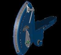
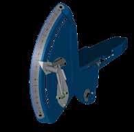
2. Set the degree meter to the tilt angle given by the spread chart (see figure 2)
3. Tilt the spreader by adjusting the top link of the tractor. It is recommended that the hopper is half full when doing so (see figure 3). This is to average out the deviation due to tire pressure etc. Depending on tractor type / size and the load capacity of the spreader, the deviation from empty to full spreader, is about 1-3 degree.
● Check that the bubble level is positioned correctly according to the fixed reference spirit level. Place the spreader horizontal and vertical leveled according to the reference spirit level – and check that the adjustable bubble level is correct adjusted at 0 degree (see figure 2 & 3)
It is also possible and recommended to check the setting of the degree meter by placing a level on the spinning discs of the spreader.
The L15(W) spreader must always be mounted in a horizontal position with a tilt angle of 0 degrees.
Spreader settings
Working height - standard
Distance from the centre of the upper link pins to the top of the crop:
M60W, M45W, M35W, L20W, M45, M35 and L20: 75 cm (see figure 1)
L15(W): 55 cm (see figure 2)
Working height - late application
Move the link pins of the spreader to the lowest position to lift the spreader as much as possible. This will minimize the risk of damage to the crop.
The tilt angle depends on the working width and the distance between the top of the crop and the spreading discs
A (see figure 1).
Find the correct addition to the tilt angle in the chart below:
Working width
Example:
Tilt addition (°)
Tilt addition (°) metres metres
Tilt angle normal spreading (15-42 metres) according to spread chart
Height above crop
Tilt angle by late application
Figure 2
Figure 1
Spreader settings
Working height - trails
If the spreader is mounted on M-Trail or other carriages – the distance from the ground to the upper link is increased from 75 cm, typically up to 100 cm to 140 cm.
Find the correct compensation to the tilt angle in the chart below:
Working width
12 - 18
20 - 36
36 - 42
Example:
H: 100 - 140 cm (see figure 1) Tilt reduction (°) metres metres metres
Tilt angle normal spreading (24 metres) according to spread chart
Tilt angle when spreader mounted on a trailer
Figure 1
Spreader settings
Quantity setting
The quantity (Kg/Ha) is set by the scale pointer of the spreader (see figure 1)
The setting system is equipped with a scale, a scale stop and a scale pointer. The scale runs from 0 to 9 in 0,25 steps. Each scale number corresponds with the quantity (Kg/Ha) on the specific working width.
With CALIBRATOR and ISOBUS
The quantity setting is made in CALIBRATOR or ISOBUS monitor.
Make sure that the scale stop is always fixed on 9.
For further instructions please see the CALIBRATOR or ISOBUS manual.
With mechanical control
It is recommended to carry out a calibration with the S-indicator to find the correct quantity setting and the corresponding scale setting.
Alternatively, the scale must be set according to the spread chart for the actual fertiliser product (see page 21)
When the correct scale setting is found, fix the scale stop accordingly (see figure 2)
Figure 2 Figure 1
Spreader settings
Quantity setting
By use of spread chart only
It is possible to find the scale setting in a spread chart for the specific fertiliser
Use our website or app to find the correct spread chart (see figure 1)
NOTE: The spread chart is only a guideline, as the quantity applied depends on the driving speed and the tramline distance, but also of the quality of the fertiliser in question. The fertiliser will change character according to temperature, air humidity and it often varies with each delivery/batch.
Example
Spreader settings
Calibration value Kg/30 sec
Scale
Outlet position
Tilt angle
Vane type
Vane positions
Normal (rpm)
TREND Headland (rpm)
DYNAMIC Headland (rpm)
Vane types
Figure
Spreader settings
Working width setting
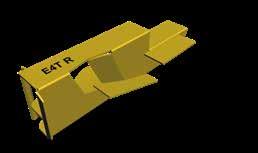
Each vane is marked with an R (right) or an L (left).
Make sure to mount the two vanes with R on the right side of the spreader and the two vanes with L on the left side of the spreader.
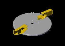
RLIn the majority of cases, the vanes are mounted in pos. 1-2 on the left spreading disc and in pos. 1-2 on the right spreading disc (see figure 1). If the vanes must be placed in another position than 1-2 – the position is defined in the spread chart for the respective fertiliser at the specific working width.
Make sure that the fixing bolt is pushed completely in the bottom of the U-shaped cut before tightening the nut. Make sure that the washer is placed between the nut and disc - and not between the vane and the disc.
With the U-shaped cut the bolt can slide into the correct position, and it is more difficult to place the vane in a wrong position by mistake. Respectively one U-Pos 1 and one U-Pos 2 on each disk.
If it is necessary to mount the vanes in alternative positions e.g. 2-3 or 3-4, the nuts and washers must be removed before installing the spreading vanes on the disc. Remember to mount and tighten the nuts and washers again before spreading. In case position 2-3 or 3-4 must be used this is indicated in the spread chart.
The vane type is chosen in relation to the required working width and/or fertiliser type (see page 63 and 66)
NOTE: The wear on the vane placed in Pos 1 is more distinct than the ware on the vane in Pos 2. The lifetime of the vanes can be extended if the two vanes are swopped 1 ► 2 and 2 ► 1 on each disc – when wearing marks is visible at the Pos 1 vane.
Figure 1
Spreader settings
Spreading vanes
The spreading vane is a key part of the spreader.
When using the Trend headland systen both sides of the vane are used for spreading. The front side is used for normal spreading (see figure 1)
When changing the direction of the discs the back side is used for headland spreading (see figure 2)
Headland spreading is done with the back side of the spreading vane in combination with the rotation of the spreading discs away from each other, when "Trend Headland" mode is selected.
Headland spreading in Trend Headland Mode Normal spreading
At headland spreading the back side of the vane reduces the speed of the fertiliser – therefore the spread distance towards headland is reduced and adapted to the distance between tramlines and border with 110° overlap.
● It is very important that the spreading vanes are intact.
● The vanes should not be deform and have wearing holes.
● Rust/paint on the surface of the vanes will be grinded off after spreading 100 – 200 Kg.
The vane type is chosen in relation to the required working width and/or fertiliser type (see page 63 and 66)
Examples:
Spreader settings
Spreading vanes
Below is shown guideline working width/vane type for the main fertiliser types in the market. Any deviation will appear on the spread chart in question.
Vane types / marks
M60W, M45W, M35W, L20W, M45, M35, L20
M60W, M45W, M35W, L20W, M45, M35, L20
M60W, M45W, M35W, L20W, M45, M35, L20
M60W, M45W, M35W, L20W, M45, M35, L20
M60W, M45W, M35W, L20W, M45, M35, L20
M60W, M45W, M35W, L20W, M45, M35, L20
M60W, M45W, M35W, L20W, M45, M35, L20
L15(W)
L15(W)
Spreader settings
Regulation system
Connection rods
The regulation system consists of a scale pointer connected to the outlet shutters through 4 connection rods.
The scale pointer must be positioned on scale number 0 when the shutters are closed (see figure 1-A)
The shutters are closed with an approx. 0,5 mm. opening (see figure 2)
If this is not the case, the scale pointer can be adjusted on the connection rod (see figure 1-B)
Especially for M-line
As default the connection rod must be mounted in the STD standard position (Ø10 mm.) (see figure 3)
In case very large/extreme quantities being spread on 28 - 42 metres spread width, the connection rod must be moved to MAX+ position (Ø12 mm.) (see page 21).
The MAX+ connection rod must only be fitted with the outlet in position MAX.
Outlet shutters
The shutters in the regulation system are factory set for the spreader to distribute the fertiliser symmetrically.
The shutters must close exactly in the middle of the V-mark of the bottom plate. When closed the distance between the shutters should be 0,5 mm (see figure 2)
NOTE: Do not adjust the 4 connection rods connecting the adjustment axle of the spreader and the shutters of the spreader. These connection rods should only be adjusted in case they have been dismantled and may be misadjusted. The setting is of great importance for the symmetry of the spread pattern.
Figure 3
Practical tests
Fertiliser analysis
The analysis can be used when there is uncertainty about the quality of the fertiliser delivered or if there is no spread chart available on the fertiliser in question.
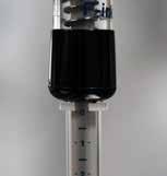
Check the quality of the fertiliser by testing the parameters of the fertiliser with the D- and F-indicator (standard equipment with all W-spreaders).
D-indicator - Grain size
The D-indicator gives an indication of the grain sizes.
1. Fill up the part marked with D on the D-indicator (see figure 1)
2. Shake the box until the grains stop changing compartments (min. 15-20 sec.) (see figure 2).
3. Read off the grouping of the grains in percentage in , , and (see figure 3)
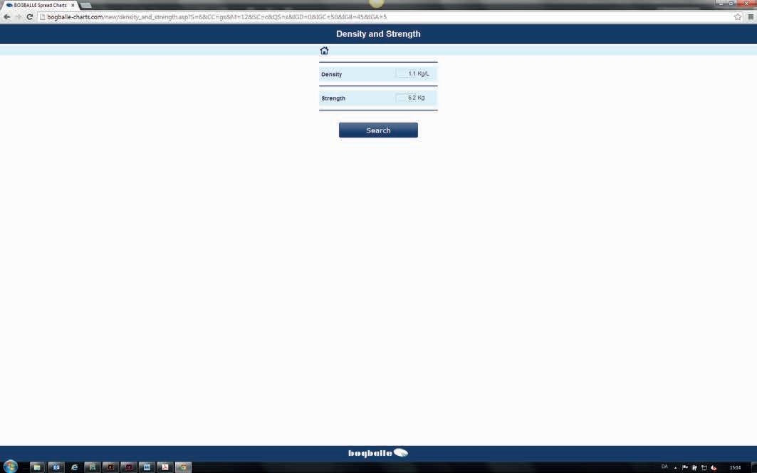
4. Enter the result in the online fertiliser analysis by choosing Spread Charts on www.bogballe.com and follow the instructions. (see figure 4)
Practical tests
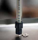
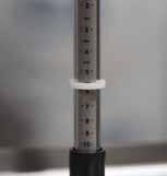
F-indicator - Grain strength
The F-indicator measures the strength of the grains in kg.
Choose 10 grains with a variation of the size and test each grain with the F-indicator
1. 0-set the F-indicator (see figure 1)
2. Place the F-indicator on top of one grain - press until the grain breaks (see figure 2)
3. Note the result (see figure 3)
4. Repeat the procedure with min. 9 more grains.
5. Calculate the average strength of the 10 grains
6. Enter the result in the online fertiliser analysis by choosing Spread Charts on www.bogballe.com and follow the instructions. (see figure 4)
With these parameters and the density (Kg/L) of the fertiliser entered in the fertiliser analysis page, the system will search the database for fertilisers with the same specifications and suggest the spread chart with the best match of fertiliser.
Practical tests
Test with trays
A tray test can be done if there are doubts about the quality and spreading ability of the fertiliser.
If carried out correctly, the tray test can help determine the spreadability of the fertiliser and help ensure a correct working width and an optimum overlap.
NOTE: The tray test must be done correctly, as wrong placement of the test trays will result in a wrong collection and followed by a possible wrong setting of the spreader.
Before testing, check that:
● The PTO speed is correct
● The distance between the tramlines is correct
● The spreading vanes are mounted and set correctly
● The spreading vanes are intact
● The correct type of vane is used
● The height of the spreader over the crop is correct
● The test trays are correctly placed - take special care that the trays are levelled in all directions (see figure 1)
Practical test
Normal spreading
1. Place the 7 test trays in an even line across the tramlines (see figure 1)
2. The distance between the trays are dependent on the working width.
3. Find the correct distance in the below table.
WORKING WIDTH (metres)
TRAY DISTANCE (metres)
NOTE: It is essential that the trays are placed levelled in all directions.
4. For each 3 metres working width, the distance between the trays is increased by 0,5 metres.
5. Spread always in 3 tramlines (see figure 1).
6. Start spreading minimum 10 metres before the trays. Stop spreading minimum 35 metres after the trays.
7. Empty the content of each tray into the corresponding tube and read the result.
8. The contents of the test trays will indicate the distribution in the field (see figure 2)
The optimum setting is achieved – and a good and even distribution is achieved.
The overlap is too small. The setting of the spreader gives an insufficient overlap. An inadequate quantity is applied between the tramlines. The tilt angle of the spreader must be adjusted in steps of +2º. Repeat the test.
The overlap is too big: The setting of the spreader gives a too big overlap. A too large quantity is applied between the tramlines. The tilt angle of the spreader must be adjusted in steps of -2º. Repeat the test.
For optimizing see page 66
Practical test
Headland spreading To border
The test will determine the quantity spread at the border compared to the quantity spread in-field.
By border spreading it is possible to change the working width ± 1 m by each ± 50 rpm.
1. Place the test trays on the border and in the field (see figure 1).
2. The distance between the trays are dependent on the working width.
3. Find the correct distance in the below table.
WORKING WIDTH (metres)
TRAY DISTANCE (metres)
NOTE: It is essential that the trays are placed levelled in all directions.
4. Make sure the rotation of the discs are set for headland spreading.
5. Spread in headland tramline with medium headland spreading settings (see page 45 and 75).
6. Calculate the result (see figure 2)
Add the contents of the three trays at the border and divide by 3 = A
Add the contents of the four trays in-field and divide by 4 = B
Divide A with B
If the test result is between 25% and 70% the spread pattern corresponds to the medium spreading.
Minimum /maximum spreading is achieved by changing the PTO speed with ±50 rpm and change the quantity by ±10% respectively.
For optimizing see page 67
Optimize spreading
Normal spreading
Example of how the tilt angle can optimize the spread pattern.
Optimum spread pattern
Tilt angle: +2
Tilt angle too low
Tilt angle: +0
Test tray collection Test tray collection
Working width 24 metres
Amount 250 kg/ha
Spread pattern including overlap
A triangular shaped curve ensures a full and correct overlap.
Spread pattern including overlap
The shape of the curve shows the overlap between the tram lines is too small.
To ensure the correct spread pattern increase the tilt angle in steps of +2º
Tilt angle too high
Tilt angle: +4
tray collection
Spread pattern including overlap
The shape of the curve shows the overlap between the tram lines is too big.
To ensure the correct spread pattern decrease the tilt angle in steps of -2º
Coefficient of variation
The coefficient of variation is an expression of the spreaders ability to distribute the fertiliser even.
Coefficient of variation: International standard
Optimize spreading
Headland spreading EN13739-1 To Border
Headland spreading can be divided into three categories:
Minimum:
The amount of fertiliser outside field border is 3 ‰ or less of the total kg/ha on 100 metres. Environmentally optimised spreading (EOS) according to EN13739-1.
Medium:
The amount of fertiliser at the border is between 25 -70 % of the kg/ha of fertiliser in the normal spread area.
Maximum:
The amount of fertiliser to the border is 90-100% of the kg/ha.
Yield optimised spreading (YOS) according to EN13739-1.
How to change the character of the To Border spreading
By changing the PTO speed it is possible to respectively increase or decrease the working width to the border.
+ 50 rpm = + 1-2 metres full amount closer to the border - 50 rpm = - 1-2 metres full amount further away from the border
To keep a constant rate it is necessary to change the application rate.
For every + 50 rpm +10%.
For every - 50 rpm -10%
The application rate is changed by using the %-regulation on all spreaders controlled electronically.
On all mechanically controlled spreaders, recalculate the Flow Factor given by the S-indicator (see figure 1)
Quantity
Working Width
Speed
Amount of fertiliser in kg
Calculation factor
[Kg/Ha] x [M] x [Km/h] x 155
Optimize spreading
Headland spreading To Border
Working width 24 metres
Amount 200 kg/ha
Example of how the PTO speed can change the spread pattern in the border area.
Minimum category (EOS)
PTO speed: 375 rpm
Spread pattern with minimum fertiliser over the border
Relative amount outside border/ha = 0,05%
Medium category
PTO speed: 425 rpm
Spread pattern moved 1 meter towards the border
Relative amount outside border/ha = 0,23%
Maximum category (YOS)
PTO speed: 475 rpm
Spread pattern moved additional 1 meter towards the border
Relative amount outside border/ha = 0,69%
Metres
Metres
Metres
Headland management
Start and stop points at headlands
The start and stop points at headlands depend on the working width and how the spreader is controlled.
To achieve the optimum overlap follow the below recommendations. Be aware that the distances to and from the tramline are the same whether spreading To or From Border (see figure 1+2)
NOTE: Below recommendations are given by 8 km/h.
Speed: 8 km/h
Corrections for speed:
+2 km/h = - 2 metres
+2 km/h = + 2 metres
Example: Speed 14 km/h and working width 24 metres
Start distance from tramline = 22 - 6 = 16 metres
NOTE: If the spreader is connected to a GPS system the start and stop points will be managed automatically
Spreading on non rectangular fields
Principle sketches
Mechanical control
After spreading the headland, do normal spreading in the tramlines. Opening and closing of the spreader is made as shown on the sketches.
Section Control Standard
When spreading, the quantity/working width is changed for each opened or closed section.
Section Control Dynamic
When spreading, the spread pattern is changed according to the shape of the field.
Spreading on non rectangular fields
Controls
M60W, M45W, M35W, L20W, L15W with CALIBRATOR or ISOBUS
Manual Section Control Standard
● After spreading the headland, do normal spreading in the tramlines.
● When entering the wedge, press either of the wedge buttons and press minus to decrease the working width in steps (see figure 1)
● When leaving the wedge, press either of the wedge buttons and press plus to increase the working width in steps (see figure 1)
Manual Section Control Dynamic (only M-line)
● After spreading the headland, do normal spreading in the tramlines.
● When entering the wedge, press the wedge button which complies to the side where the wedge is (see figure 2)
● Press minus to adjust the spread pattern in steps (see figure 2).
● When leaving the wedge, press the wedge button which complies to the side where the wedge is (see figure 2)
● Press plus to adjust the spread pattern in steps (see figure 2)
With GPS control
● After spreading the headland, do normal spreading.
● With the CALIBRATOR or ISOBUS automatically controlled by GPS, the adjustment is done automatically.
● For more information see manual from the manufacturer of the GPS system.
Spreading on non rectangular fields
Controls
M45, M35, L20, L15 with CALIBRATOR ICON
Manual Section Control Standard
● After spreading the headland, do normal spreading in the tramlines.
● When entering the wedge press minus to decrease the quantity/working width in steps.
● When leaving the wedge press plus to increase the quantity/working width in steps.
With GPS control
● After spreading the headland, spread normally in the tramlines.
● With the CALIBRATOR ICON automatically controlled by GPS, the adjustment is done automatically. For more information see manual from the manufacturer of the GPS system.
M45, M35, L20 with CALIBRATOR
Manual Section Control Standard
● After spreading the headland, do normal spreading in the tramlines.
● When entering the wedge, press either of the wedge buttons and press minus to decrease the working width in steps (see figure 1).
● When leaving the wedge, press either of the wedge buttons and press plus to increase the working width in steps (see figure 1)
With GPS control
● After spreading the headland, do normal spreading.
● With the CALIBRATOR automatically controlled by GPS, the adjustment is done automatically. For more information see manual from the manufacturer of the GPS system.
Spreading on non rectangular fields
Controls
M45, M35 with CALIBRATOR
Manual Section Control Dynamic (only M-line)
● After spreading the headland, do normal spreading in the tramlines.
● When entering the wedge, press the wedge button which complies to the side where the wedge is (see figure 1)
● Press minus to adjust the spread pattern in steps (see figure 1).
● When leaving the wedge, press the wedge button which complies to the side where the wedge is (see figure 1).
● Press plus to adjust the spread pattern in steps (see figure 1)
With GPS control
After spreading the headland, do normal spreading.
With the CALIBRATOR automatically controlled by GPS, the adjustment is done automatically. For more information see manual from the manufacturer of the GPS system.
Wedge width
Reduced working width
Principle sketches
Mechanical control and Section Control Standard
When spreading the quantity/working width is adapted to the remaining part of the field (see page 78 or 79).
Working width
Remaining part of the field
Section Control Dynamic
When spreading the spread pattern is adapted to the remaining part of the field (see page 78 or 79).
Working width
Remaining part of the field
Reduced working width
Controls
M60W, M45W, M35W, L20W, L15W with CALIBRATOR or ISOBUS
Manual Section Control Standard
Reduce the working width by pressing either of the wedge buttons and press minus to decrease the working width to the reduced spread width (see figure 1)
Manual Section Control Dynamic (only M-line)
Reduce the working width by pressing the wedge button, which complies to the side where the remaining part of the field is (see figure 2)
Press minus to decrease the working width to the reduced spread width (see figure 2)
With GPS control
With the CALIBRATOR or ISOBUS automatically controlled by GPS, the adjustment is done automatically. For more information see manual from the manufacturer of the GPS system.
M45, M35, L20, L15 with CALIBRATOR ICON
Manual Section Control Standard
Set the working width to remaining part of the field.
With GPS control
With the CALIBRATOR ICON automatically controlled by GPS, the adjustment is done automatically. For more information see manual from the manufacturer of the GPS system.
Reduced working width
Controls
M45, M35, L20, with CALIBRATOR
Manual Section Control Standard
Reduce the working width by pressing either of the wedge buttons and press minus to decrease the working width to the reduced spread width (see figure 1)
Manual Section Control Dynamic (only M-line)
Reduce the working width by pressing the wedge button which complies to the side where the remaining part of the field is (see figure 2)
Press minus to decrease the working width to the reduced spread width (see figure 2)
With GPS control
With the CALIBRATOR automatically controlled by GPS, the adjustment is done automatically. For more information see manual from the manufacturer of the GPS system.
Reduced working width
Controls
M45, M35, L20, L15 with mechanical control
Reduce the working width by calculating a new flow factor using the S-indicator (see figure 1) Insert the quantity, the remaining width of the field, the speed and the weighted grams.
Example
Calculating new FlowFactor - remaining part of the field = 8 metres
[Kg/Ha] x [M] x [Km/h] x 155 [Gx]
Maintenance and care
Lubrication
The components below must be lubricated according to below instruction.
Cross joint and lock of the PTO
Adjustment axle (cross axle w/ 4 bearings) Use oil
Setting handle (axle w/ 2 bearings)
Connection rods (rods between axle and shutters)
Agitator R and L (under cone)
Use oil
Use oil
Use grease
*Please notice that high pressure from too much oil/grease will restrict the rotation of the agitator bearing. In such a case the lubricator nipple must be demounted to release the pressure.
Nuts and bolts
● All nuts and bolts of the spreader must be retightened after the first 5 to 8 hours of operation (see page 11)
NOTE: The bolts in the central and angle gears are locked with lock-tite and do not need retightening. Stainless nuts and bolts may fuse together - the thread must be greased with cutting lubricant graphite or copper grease.
Spreading vanes
● The vanes must be considered as a wearing part.
● Change the vanes if they are deformed or if they are worn and have holes.
Maintenance and care
Normal maintenance
● Cover the entire spreader with protection oil before using it first time. Remember always to cover the entire spreader in corrosion protective oil. It is not sufficient only to wash the spreader, as dry fertiliser will absorb water and escalate a corrosion.
NOTE: The spreader must always be thoroughly cleaned after use. The cleaning should be done with water preferably with soap. When using a high-pressure cleaner only use low pressure and do not clean directly on the seals of the transmission (figure 1)
● Do not use grease removing cleaning liquid.
● Without the oil protection, rust can arise within a few hours in areas, where the paint has been damaged.
● Any paint damage should be cleaned and painted. It is possible to treat the damage with Tectyl or a similar product.
● Be aware that some cleaning products and corrosion protecting oils contain solvents that can dissolve the glue on the stickers.
Friction clutch
The friction clutch protects the reversible gear system of the transmission against overload.
● Check that the clutch is not corroded. It must slip when the PTO shaft is started. If the clutch does not slip the transmission will be damaged.
● The friction clutch slips approximately 1-2 turns when the PTO shaft is started. This reduces the load to 1/10.
● The clutch must be separated and cleaned if the spreader has not been used for more than 12 months. It is always necessary to start the tractor’s PTO smoothly
How to clean the friction clutch
● Demount the 6 bolts of the clutch and separate the clutch (figure 1)
● Clean all the slip surfaces for rust and reassemble the bolts. If needed replace the clutch plates (figure 2)
● Do not grease the clutch.
● The bolts are tightened with a torque wrench: 60 Nm
● The splined axle has to slip at: M-line 280-350 Nm
Remember always to grease the entire spreader in a corrosion protective oil. It is not sufficient just to wash the spreader, as dried-in fertiliser dust will absorb water and escalate corrosion.
Mineral fertiliser is extremely corrosive and often with a high content of nitrogen and sulphur, which combined with water generate sulphuric acid.
Remember to:
• Cover/oil the spreader carefully before using it the first time.
• Oil seals up joints and connections between components – to prevent fertiliser dust from getting in and building up between the various spreader parts.
• Wash and grease/oil the spreader after every use.
• Store your spreader indoor Corrosion
Corrosion caused by insufficient cleaning and protection is not covered by warranty!
Safety - Axle load
Axle load
Axle load distribution
Mounting of front or rear three-point linkage implements, shall not result in exceeding the maximum permissible weight, the permissible axle loads and the tyre load carrying capacities of the tractor. The front axle of the tractor must always be loaded with at least 20% of the unloaded weight of the tractor.
Axle load on public roads must comply with national restrictions.
Make sure before loading an implement that these conditions are fulfilled by carrying out the following calculations or by weighing the tractor/implement combination.
[kg] Unladen weight of tractor (see the tractor´s manual)
[kg] Front axle load of unladen tractor (see the tractor´s manual)
[kg] Rear axle load of unladen tractor (see the tractor´s manual)
[kg] Combined weight of rear mounted implement/rear ballast
[kg] Combined weight of front mounted implement/front ballast
[m] Distance from centre of gravity for combined front mounted implement/front ballast to front axle centre
[m] Tractor wheelbase
[m] Distance from rear axle centre to centre of lower link balls
[m] Distance from centre of lower link balls to centre of gravity for combined rear mounted implement rear ballast (see table)
Safety - Axle load
Axle load
Spreader model
M60W
M45W
M45
M35W
M35
L20W
L20
L15W 0,54 m Max. 1924 kg
Determination of the total weight, the axle loads, the tyre load carrying capacity and the necessary minimum ballasting. R
Rear mounted Implement and front/rear combinations.
Calculation of minimum ballasting at the front I Fmin
Front mounted implement
L15 =
Calculation of the minimum ballasting at the rear I Rmin
(“x” see the indication of the tractor manufacturer, if no indication x = 0,45)
Calculation of the real front axle load T Freal
Calculation of the real total weight W real
Calculation of the real rear axle load T Rreal
Safety - Axle load
Axle load
Type the calculated data and the given data from the tractor manual into the table.
Tyre load carrying capacity
Table Real value according to calculation
Minimum ballasting front/rear
Total Weight
Front axle load
Rear axle Load
Permissible value according to instruction handbook
Double permissible tyre load carrying capacity (two tyres)
The minimum ballasting has to be attached to the tractor either in form of a mounted implement or ballasting weight.
The calculated values must be less or equal (≤) the permissible values.
Example: Fertiliser spreader M35W mounted on John Deere 6190R tractor
Calculation of minimum ballasting at the front IFmin
Calculation of the real front axle load TFreal
Choose 1200 kg to decrease the rear axle load.
Calculation of the real total weight W real
Calculation of the real rear axle load T Rreal
Type the calculated data and the given data from the tractor manual into the table on the next page.
Safety - Axle load
Axle load
Tyre load carrying capacity
Table Real value according to calculation
Minimum ballasting front/rear
Total Weight
Front axle load
Rear axle Load
Permissible value according to instruction handbook
Double permissible tyre load carrying capacity (two tyres)
The minimum ballasting has to be attached to the tractor either in form of a mounted implement or ballasting weight.
NOTE: The calculated values must be less or equal (≤) the permissible values.
Directive of 17th May 2006 conc. mutual approximation of the laws of the member states on machines (2006/42/ EC), with special reference to the enclosure II, A and enclosure I of the directive, conc. essential safety and health claims in connection with construction and manufacture of machines.
International/national standards:
DS/EN ISO 12100
DS/EN ISO 13857
DS/EN ISO 4254-1 A1
DS/EN ISO 4254-8
ISO 500 -3
DS/EN 12965
When mounted with CALIBRATOR / ISOBUS Controller: Is made in conformity with: directive of 26th February 2014 conc. mutual approximation of the laws of the member states on electromagnetic compatibility (2014/30/EU) (EMC direktive)