Havee Kestay
Architectural
Designer
Vestal, New York
United States (607) 372-9760 · haveek o.edu
Skills
Microsoft PowerPoint
Adobe Lightroom
Adobe Illustrator
Adobe Photoshop
Adobe InDesign
Lumion
AutoCAD
Rhino 3D
Revit
Communication Skills
Computer Skills
Languages
English
Kurdish
Profile
Recent graduate of the Univ of Architecture and Planning with a strong passion for architectural design. Skilled in model-making, conceptual sketching, and program diagramming, developed through a hands-on "thinking through making" approach. Committed to designing with vision, precision, and confidence, while understanding the critical role of architecture in shaping society
Employment History
Sales Associate, Gap, Vestal
July 2023 — August 2024
Education
Architecture BS, University at Bu
January 2020 — January 2024
TOWN HALL IN FREIBURG
Floor Plan Detail
Linked
Housing For All | Fall 2023 | Jin Young Song Studio In collaboration with: Sandra Zarub
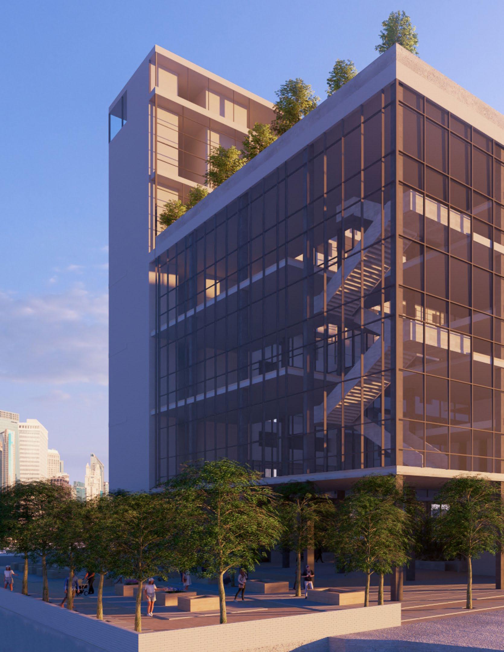
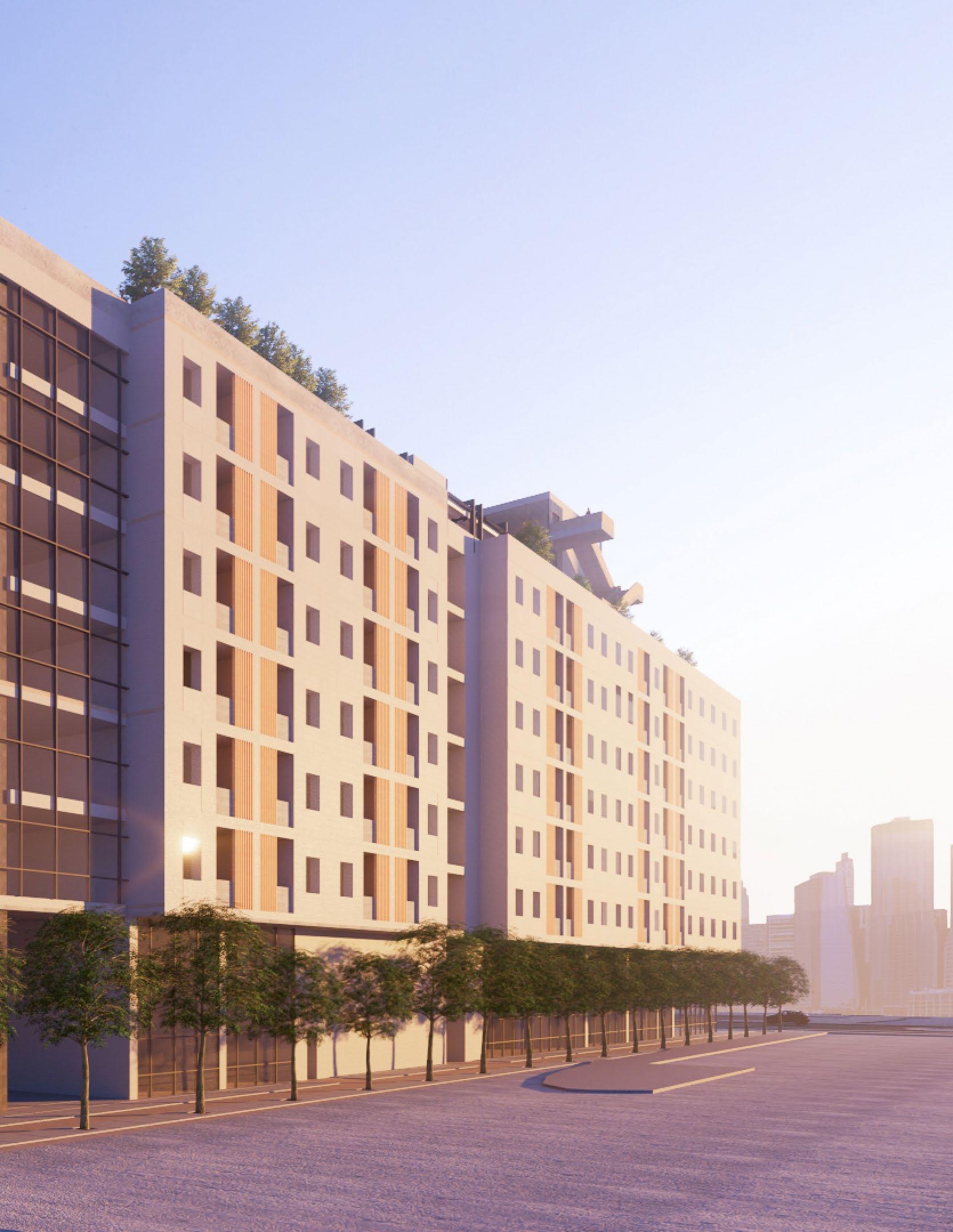
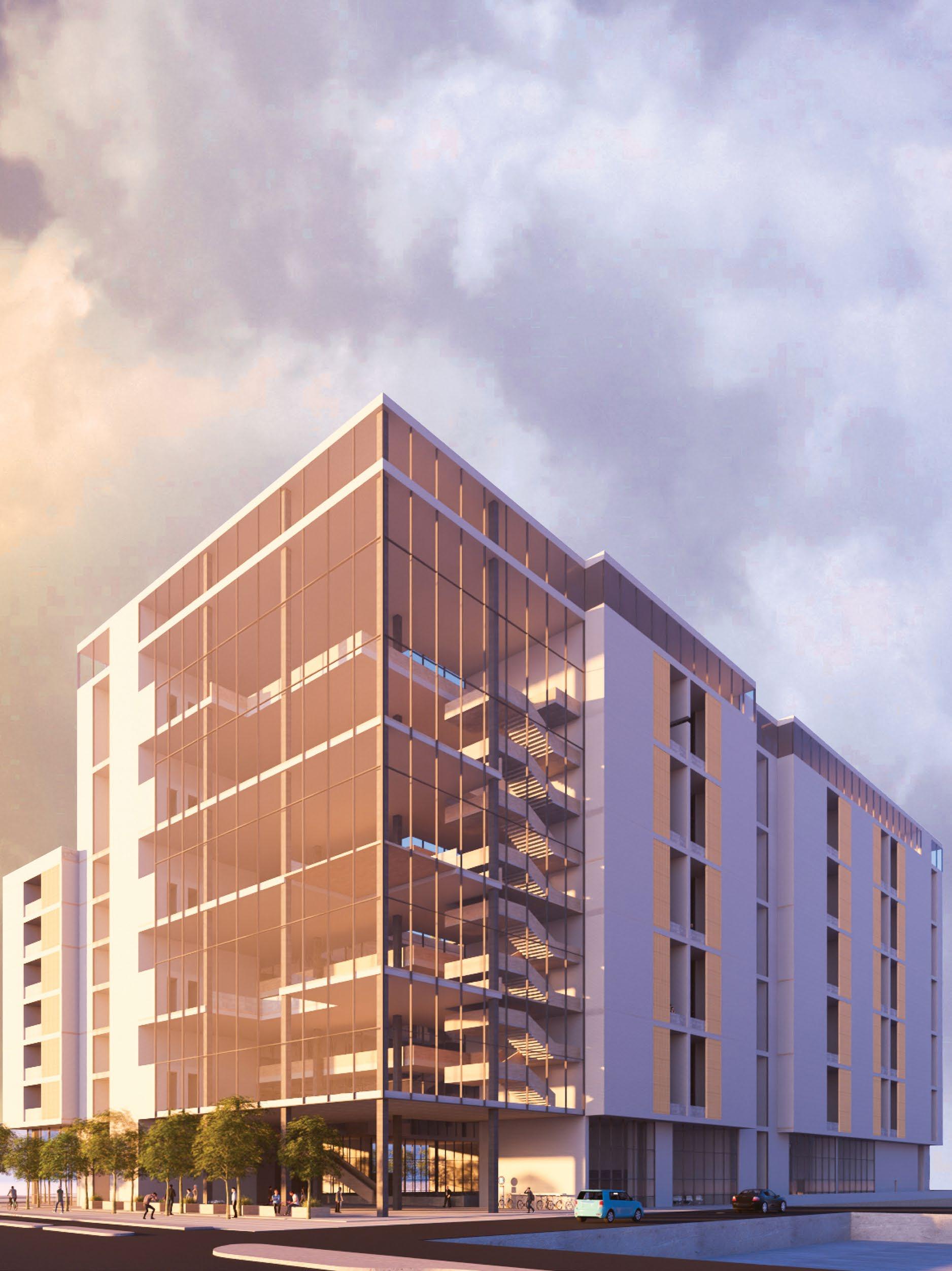
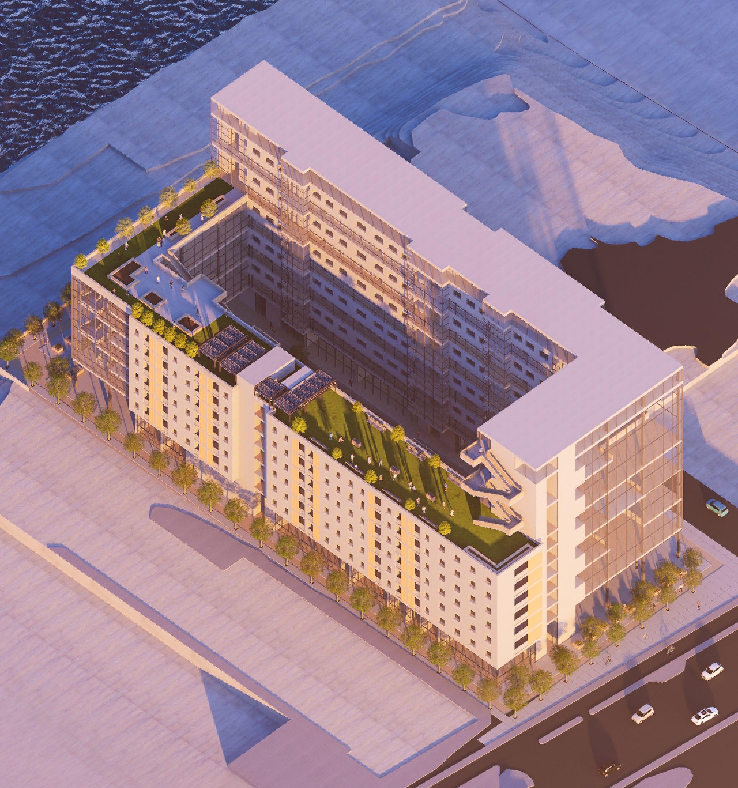
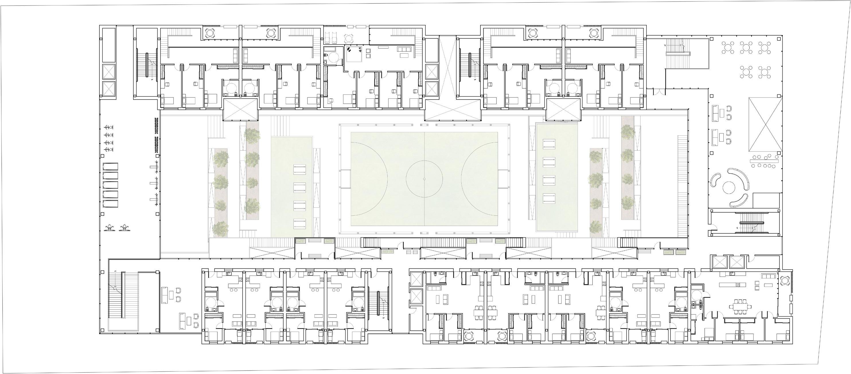
This project strives to provide a space that encourages social interaction at various levels . To cultivate these connections among residents , our design incorporates large areas of social spaces that are all interconnected around a vertical courtyard.
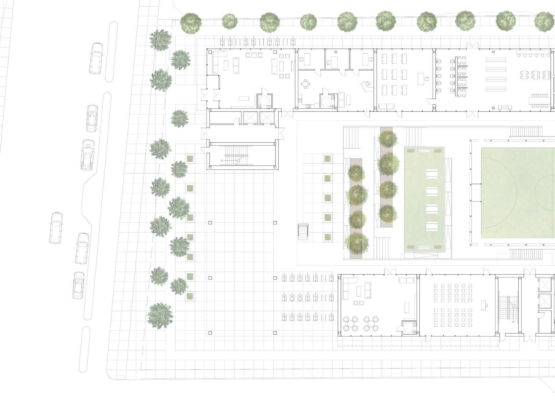
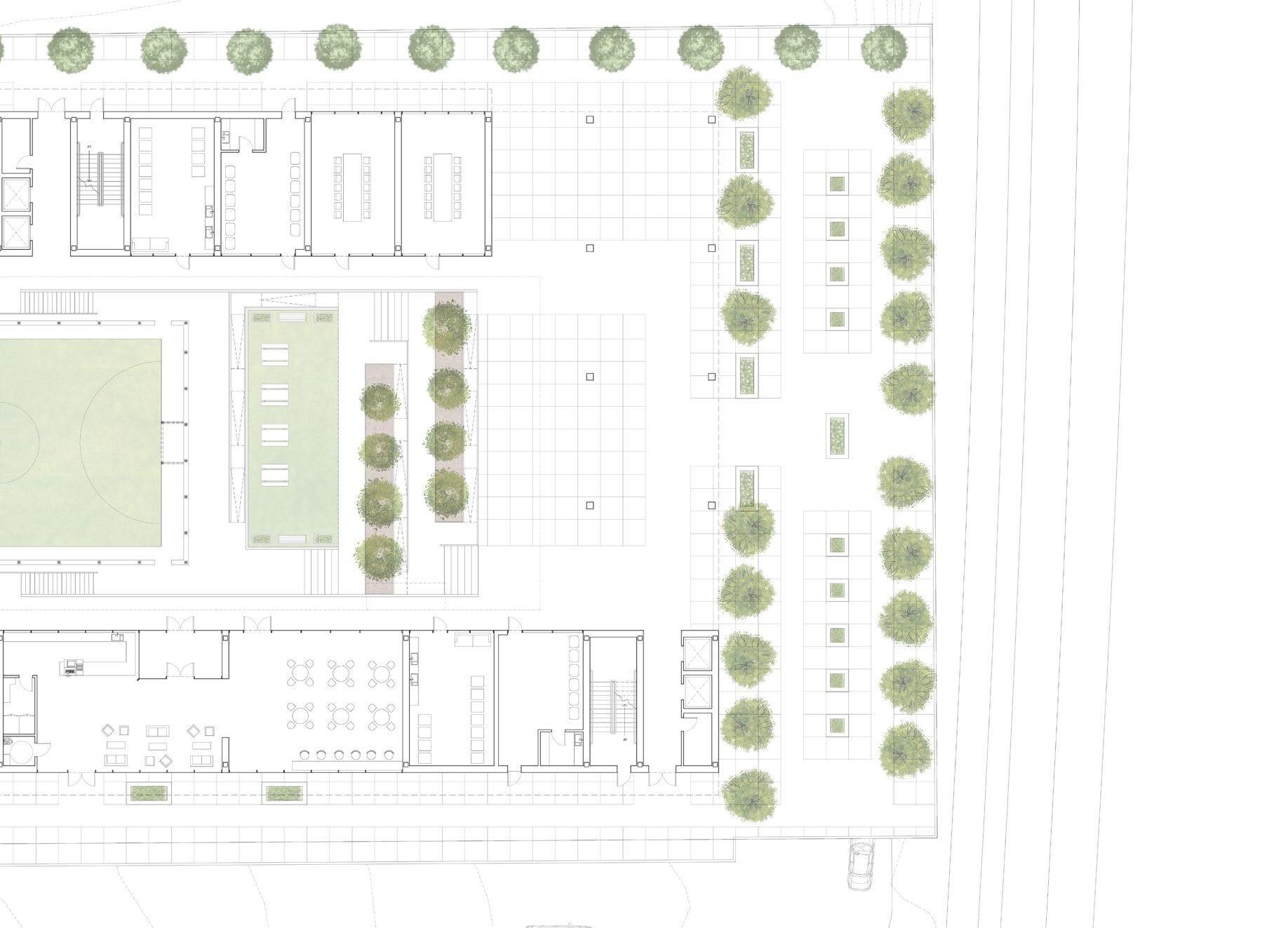
The ground floor is dedicated to public amenities and includes programs such as lounges, classrooms, laundry, and more. The corners of our building are L-shaped and are open, double height, social spaces with glass facades. These hubs are then connected through the corridors that contain interior and exterior balconies that also provide small pockets of social interaction.
To further the connectivity of the project, social stairs are located in the hubs , and also connect the public balconies around the courtyard. This system not only connects the social spaces to each other, but to the units and residents as well. With these mea sures, the courtyard is activated and residents have numerous modes of interaction that strengthen the community.
1989 Quotas for Soviet refugees raised
1980 Overall quotas for refugees raised
1975 Increased refugees from Vietnam
Concept Model
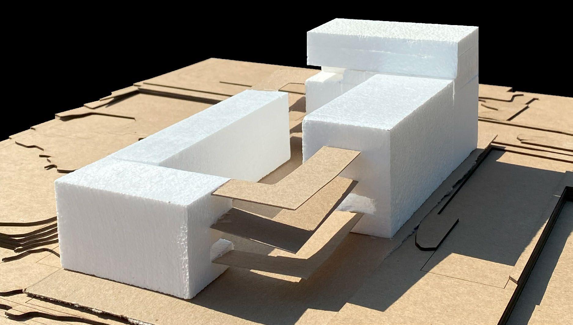
Massing Diagram
Mass Allow for more southern lighting
View Towards Water
Adjust Height of Massing
Creating the courtyard
Deliniating Social and Private Spaces
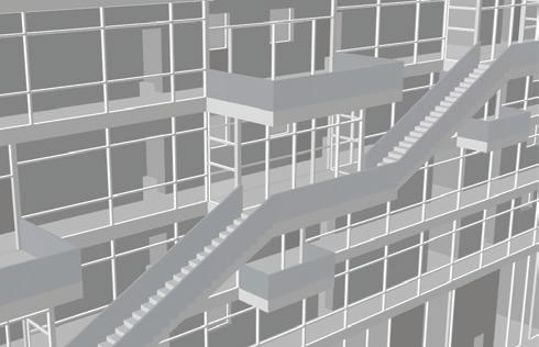
Public Spaces Through Balconies/Courtyard
Large Social Programs
Game Room
Green House
Gym
Multi-Purpose Room
Lounge
Cultural Space
Lounge
Lounge
Kids’ Lounge
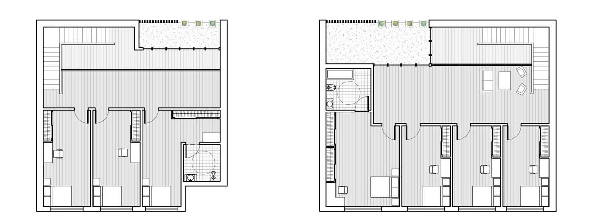
Typical Unit Plans
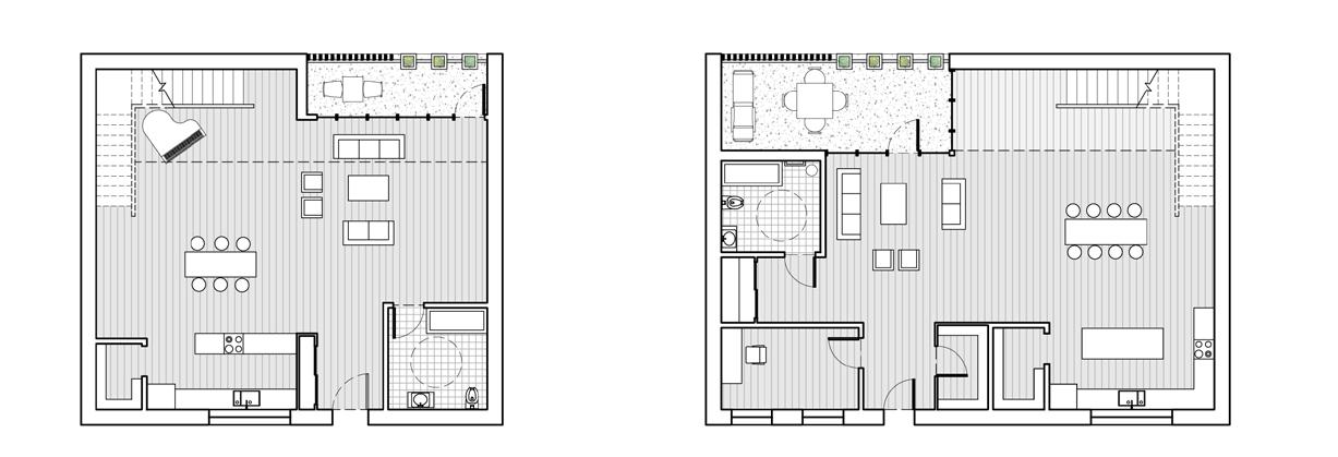
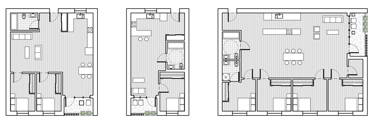
Project Metrics
Type Diagram
Project Metrics
1 Bedroom Units - 18 Units 2 Bedroom Units
20 Units 4 Bedroom Units
6 Units
Bedroom Units (Skip-Stop)
GROUND FLOOR PLAN
SECTION A’-A’


Gull Street
FLOOR PLAN
FOURTH FLOOR PLAN
The Cave
Community Center | Spring 2023 | Brad Wales
In collaboration with: Natalie Freund
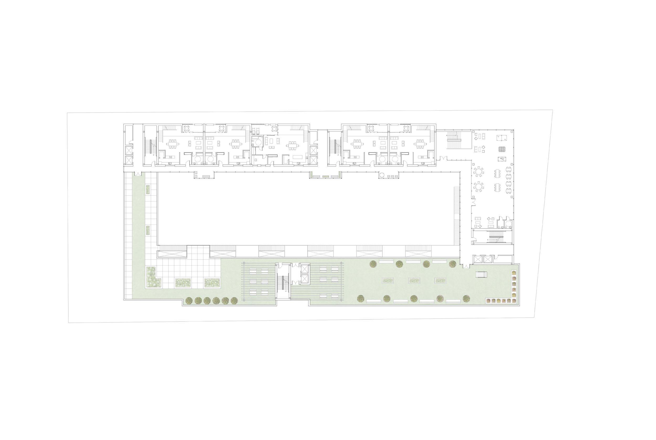
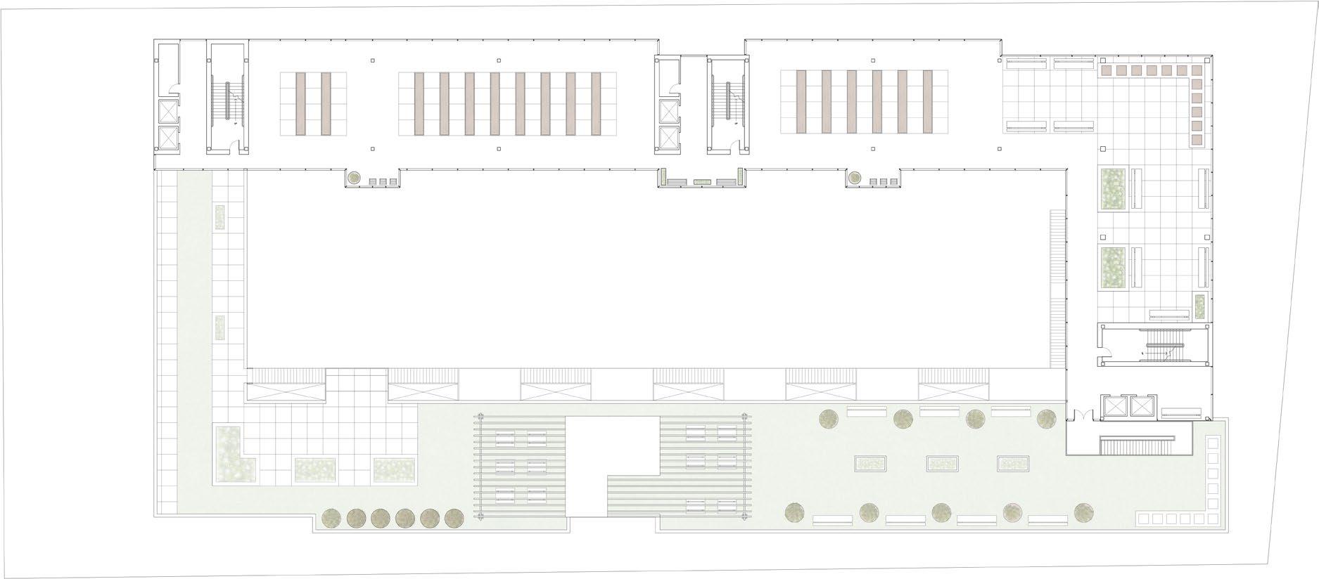
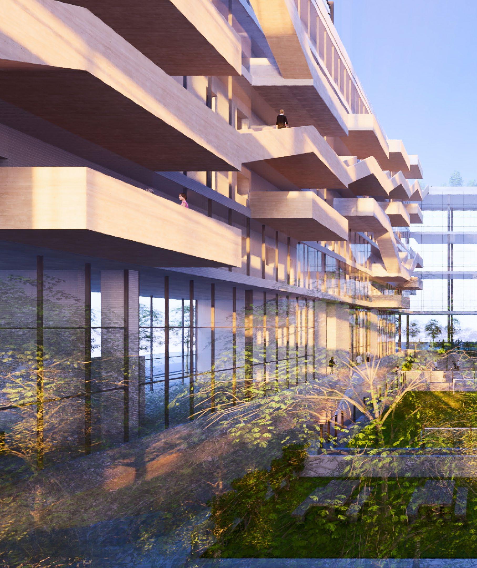
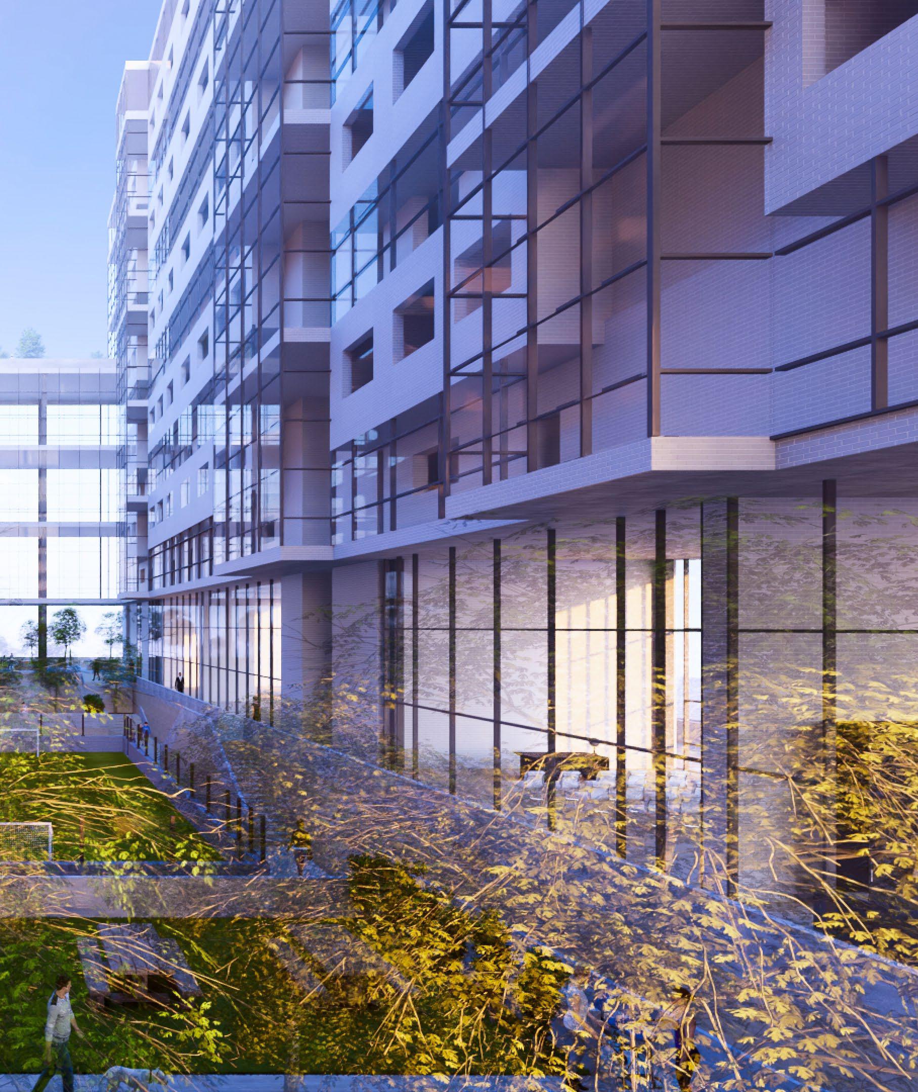
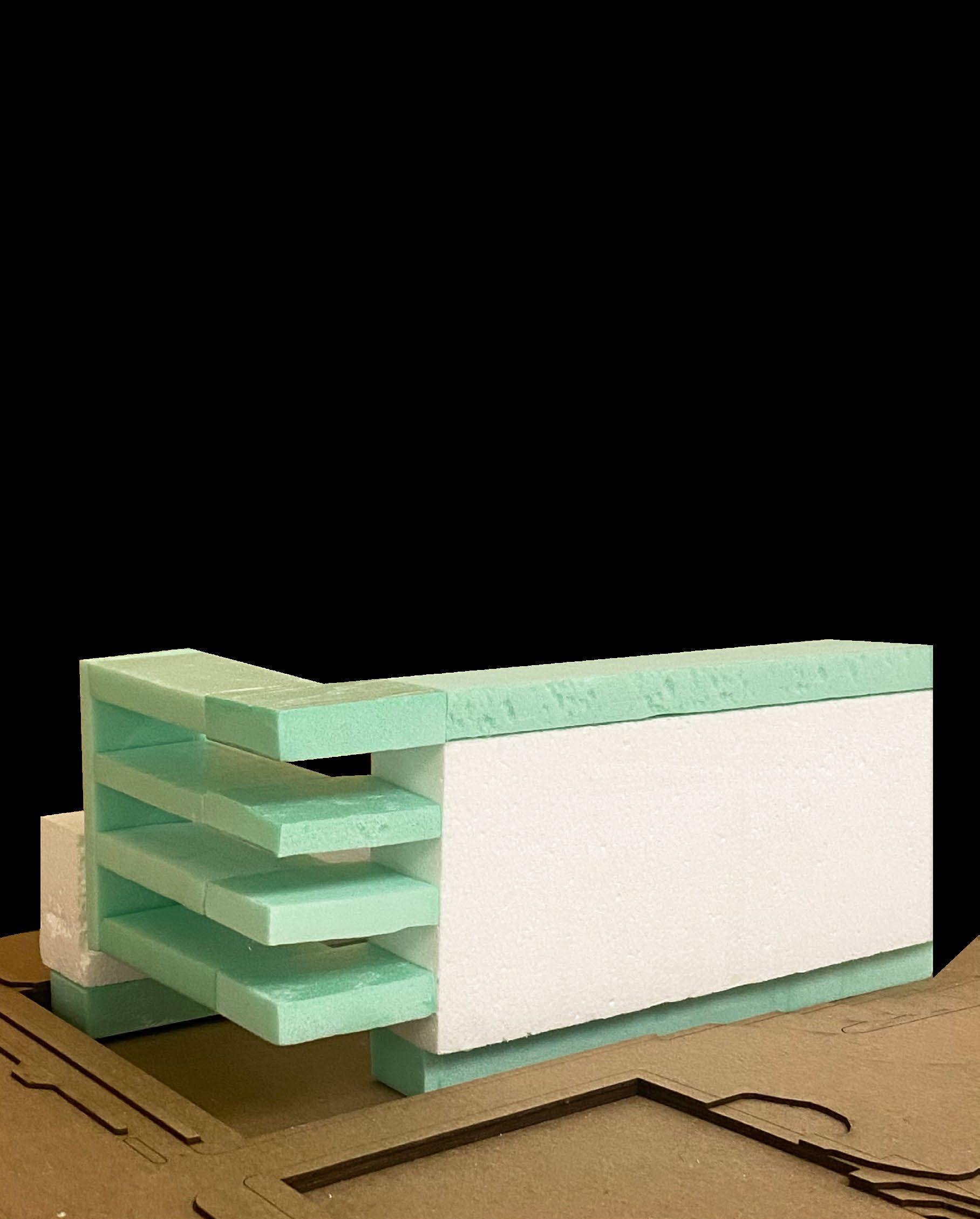
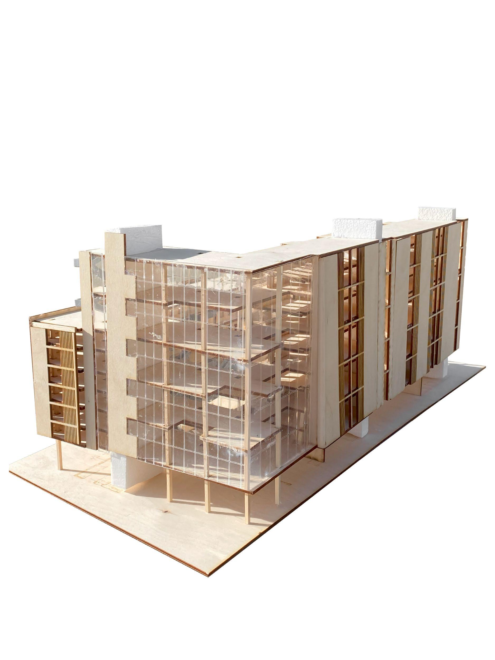
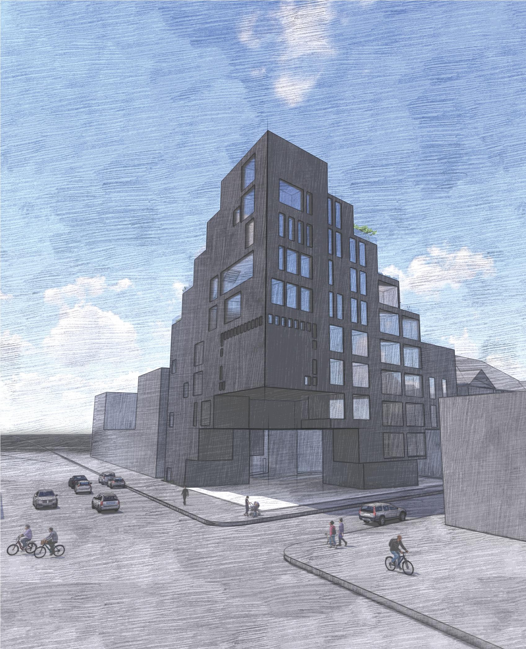
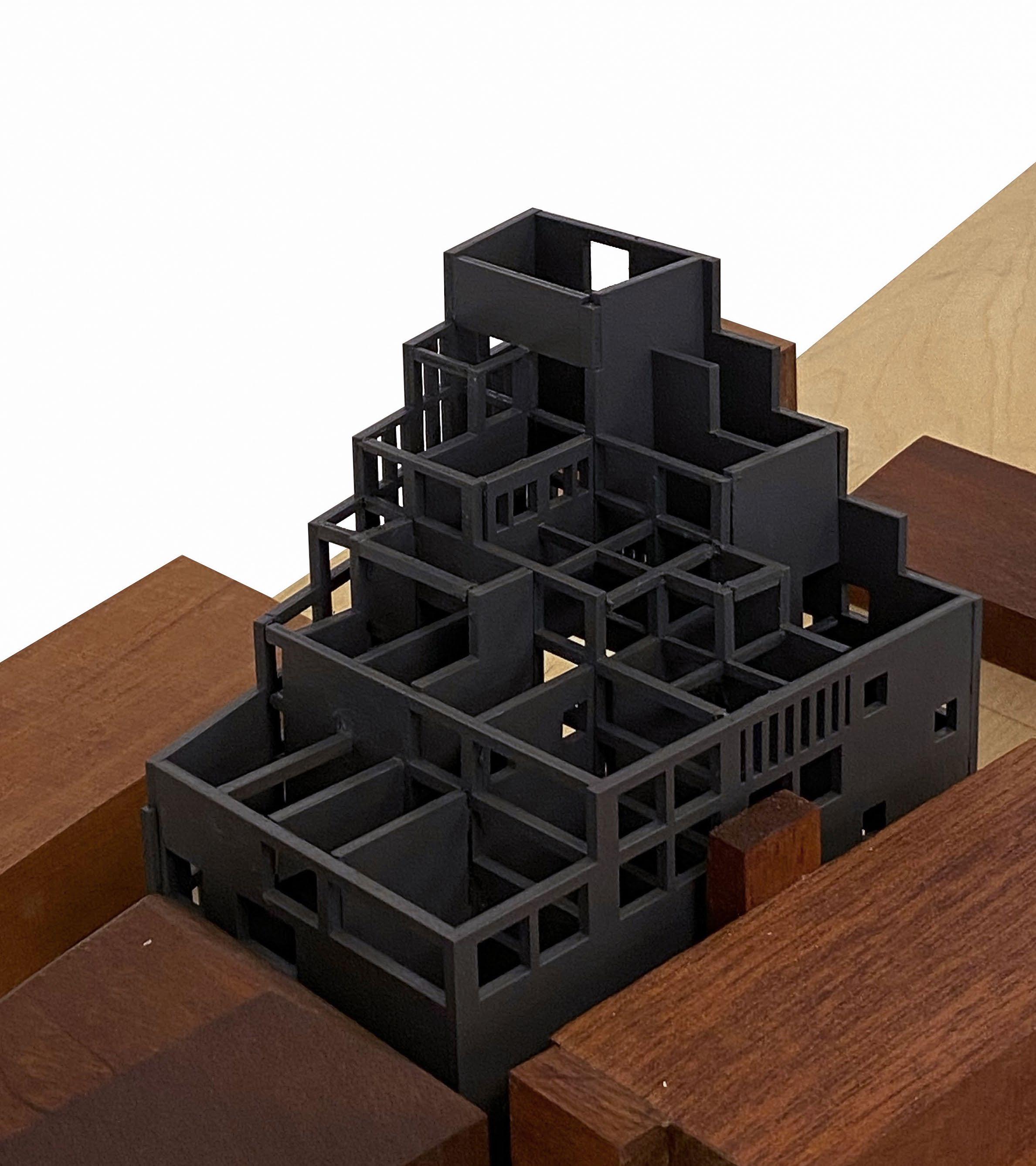
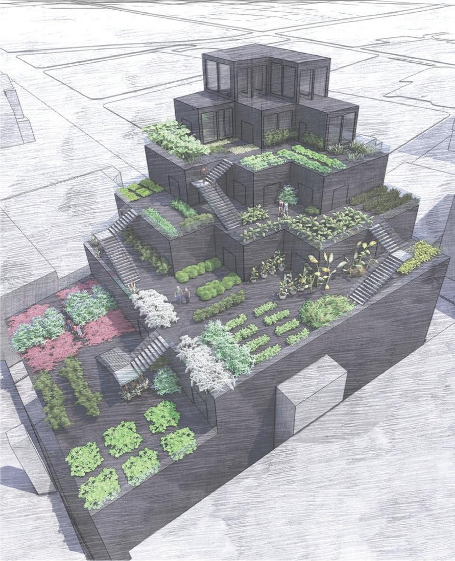
Our architectural project aims to establish rooftop terraces as growing spaces for the community , enabling the sale of locally produced food at a weekly farmers market located on the ground floor
To achieve this, we have designed an enclosed ground floor area with a captivating glass facade , enticing people to explore the market inside where community-grown produce is available for purchase.
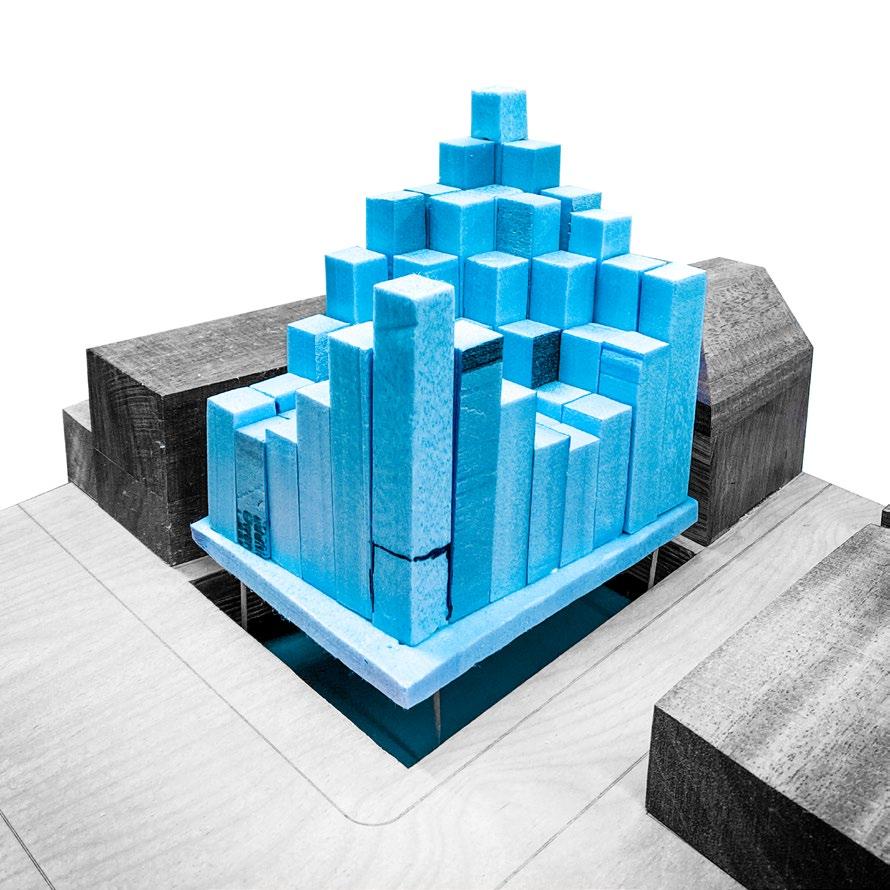
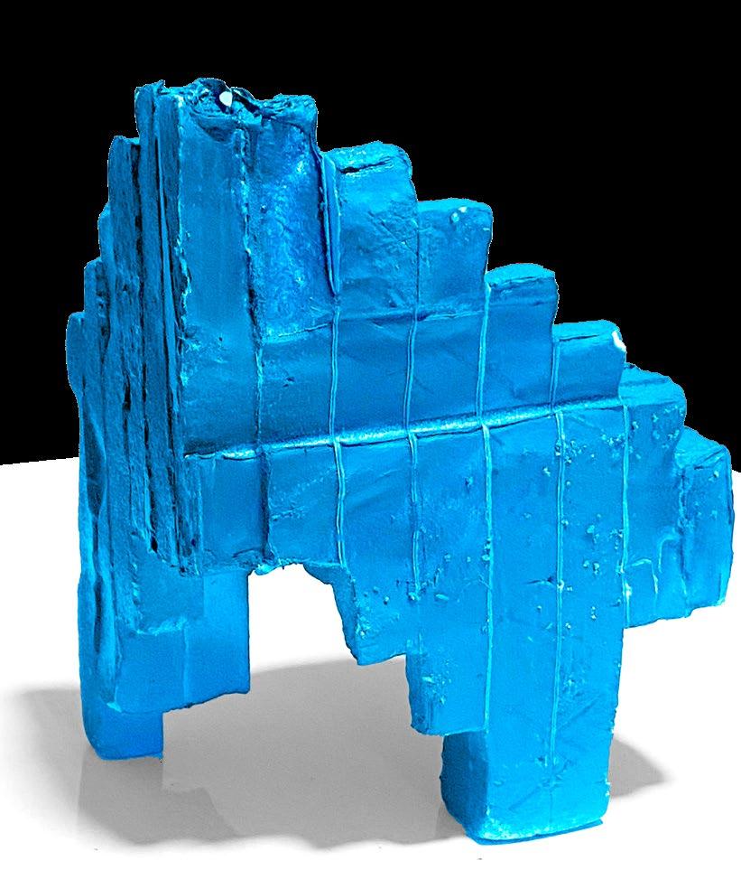
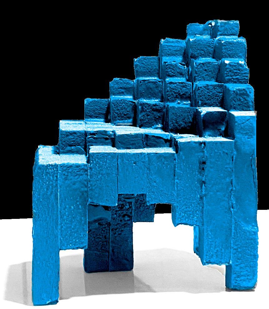
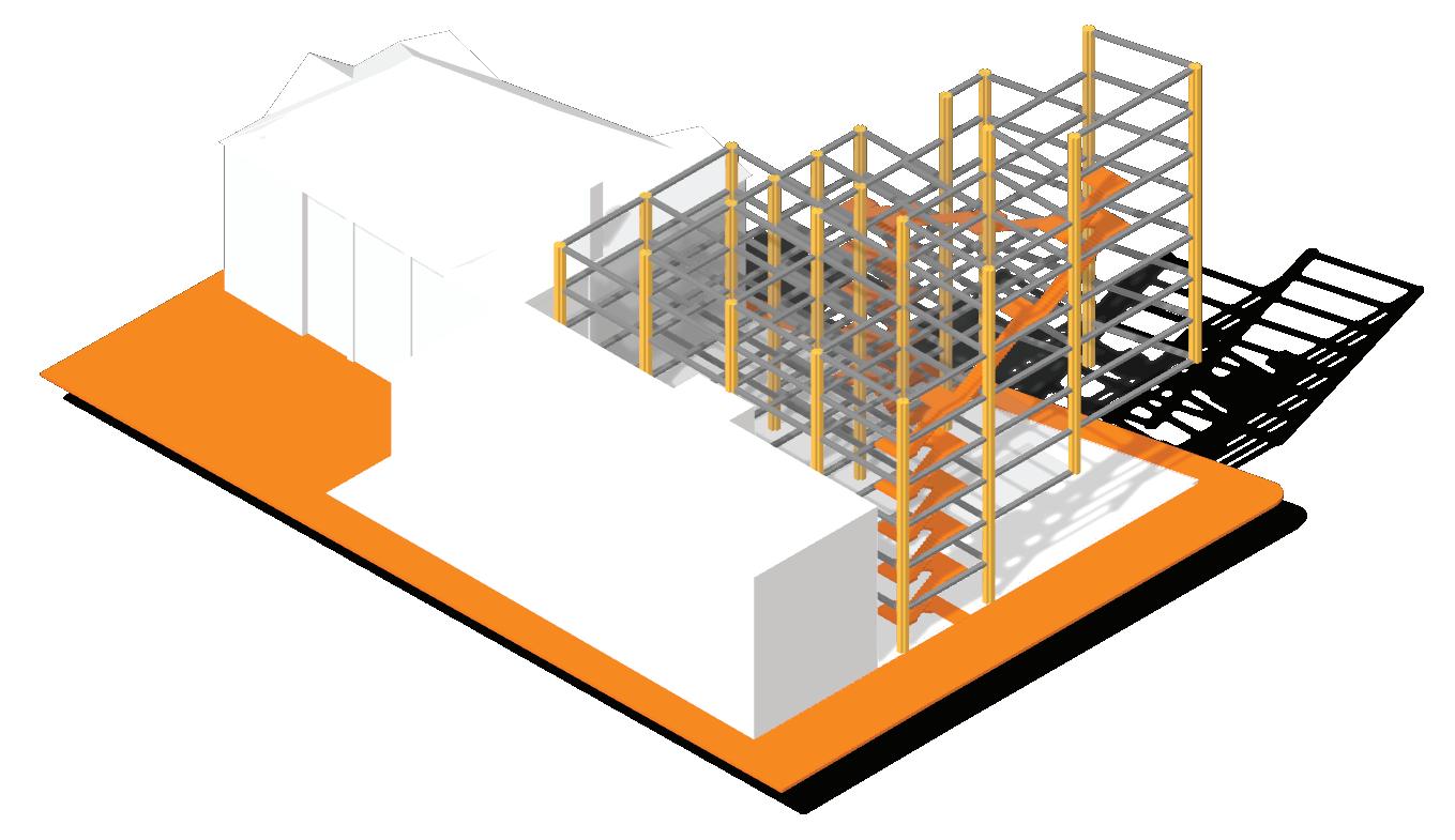
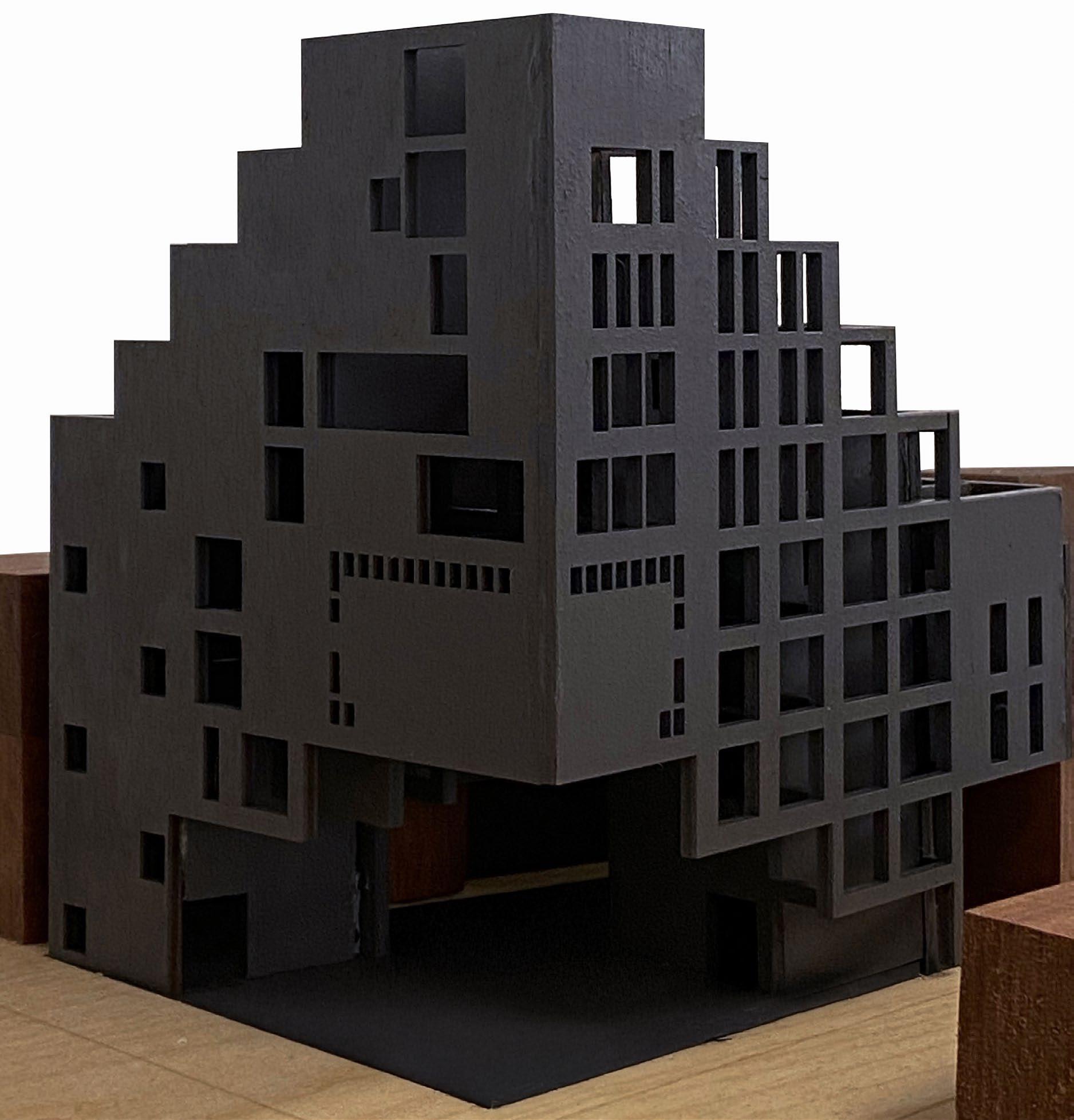
To optimize efficiency , we employed a stepped massing approach that repeats throughout the project. Our structural grid follows a 30-foot oncenter configuration, with a sub-planning module of 15 feet. This layout ensures a harmonious repetition of elements while supporting the overall functionality of the building.
For the structural integrity of the project, we utilized 4-way piers with cast-in-place (CIP) walls, serving as lateral bracing elements. To enhance insulation and protection, the exterior of the building is enveloped with insulation and cladding .
Concept Models
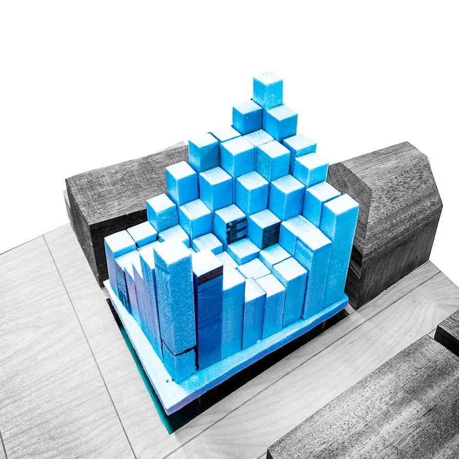
Chosen Concept Model


North Street
THIRD FLOOR PLAN
SECOND FLOOR PLAN



















SOLAR PANELS
52 39”x 78”
Angled towards the south for optimal sun absorption
RAINWATER COLLECTION
Cistern located on the fourth floor holds rainwater. Pipes distribute water throughout the building and to the growing spaces on the upper levels.
MARKET SPACE
GROWING SPACES
Rooftop gardens use the south-facing form of the building and the rainwater distribution system to grow crops that can be sold in the market space on the ground floor.


The open lobby space on the ground floor leaves room for venders to set up tables and sell produce from the rooftop gardens.
GENERATOR
Generator room located on the main floor connects to the solar panels on the roof to provide power in emergency situations an power outages.
VENTILATION WINDOWS 24” ventilation windows 6’ up provide ventilation to spaces that don’t require larger windows.

EXTERIOR WALL DETAIL
8 Inch cast-in-place concrete
6 Inch insulation
2 Inch concrete panels
FLOOR DETAIL
2 1/2 Inch concrete topping slab 1/2 Inch radiant floor heating tubes
6 Inch reinforced cast-in-place concrete
24x36 Inch beam
CEILING DETAIL
Wood panel dropped ceiling Exposed cast-in-place beams
8 Inch exposed spiral ducts
COLUMN DETAIL
28 Inch concrete beam
4 Inch insulation


FLOOR/WALL DETAIL


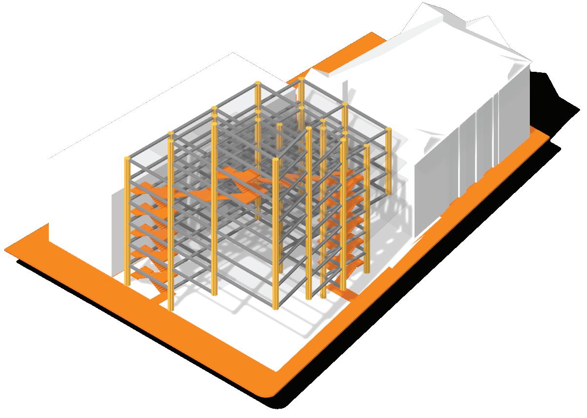
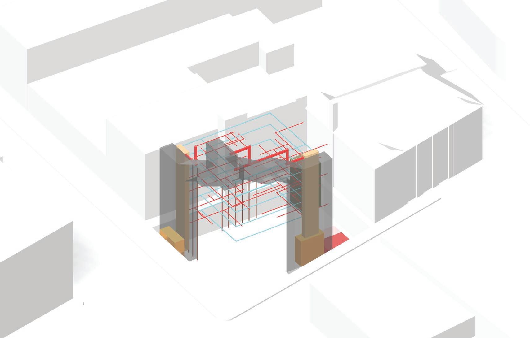
MECHANICAL AXONOMETRIC
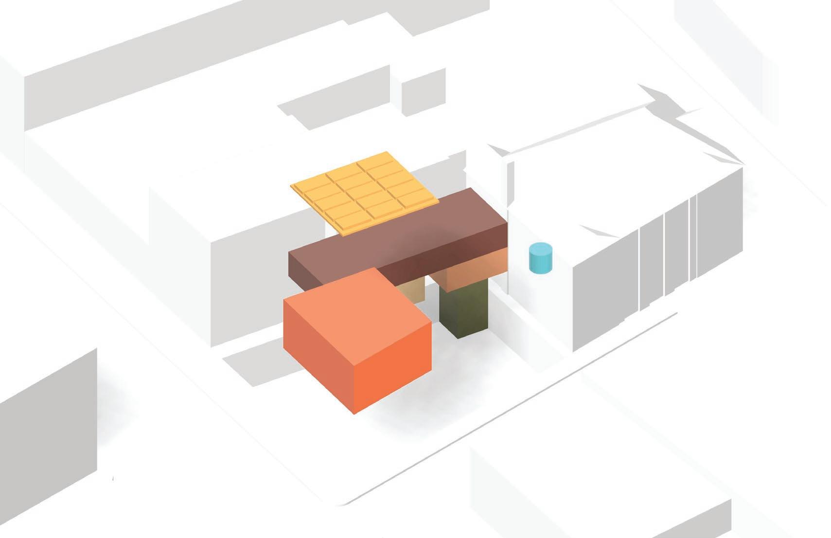
RESILIENCY AXONOMETRIC
Structural Model Photos

TOWN HALL IN FREIBURG
Ingenhoven Architects
SPECIFICATION NOTES:
1. ROOF
70 mm (3inch) gravel
4 mm (1/8 inch) building protection mat
Two-ply elastomeric bitumen
membrane
300 mm (12 inch) PIR thermal insulation
vapour barrier
320 mm (13 inch) reinforced concrete slab
2. TYPICAL FLOOR
Raised floor panels on pedestals for services distribution
Reinforced concrete slab
3. COLUMN
320 mm (13 inch) reinforced concrete column
4. EXTERIOR ENVELOPE (INNER LAYER)
WINDOW:
Triple glazing with 2x4 mm laminated safety glass
14 mm (1/2 inch) cavity
6 mm (1/4 inch) cavity
14 mm (1/2 inch) cavity
2x4 mm laminated safety glass
130/60 mm (5/2 inch) aluminum mullion-transom system
OPEN VENT:
3 mm (1/8 inch) aluminum sheet, powder coated
80 mm (3 inch) mineral wool thermal insulation
3 mm (1/8 inch) aluminum sheet, powder coated
SPANDREL CLADDING:
3 mm (1/8 inch) aluminum sheet cladding, powder coated
5. EXTERIOR ENVELOPE (OUTER LAYER)
12 mm (1/2 inch) mono-crystalline photo-voltaic module
45 mm (2 inch) back ventilation space
18 mm (3/4 inch) three-ply larch panel
PANEL SUPPORT:
80/12 mm (3/ 1/2 inch) aluminum frame, powdercoated
60/4 mm (2- 3/8 / 1/8 inch) aluminum tube as sleeve
Extruded section 5 mm (1/4 inch) aluminum sheet, powder coated + 20 mm (3/4 inch) air gap + 5 mm (1/4 inch) aluminum sheet, powder coated

MENEFEE CABIN
Clark & Menefee Architects
SPECIFICATION NOTES:
1. FOUNDATION
42”x12” Site Cast Concrete #5 Reinforcement Bar
2. EXTERNAL WALL BELOW GRADE
CMU 8”x16”x16” Rigid Board Insulation 1” Draining Tube
3. EXTERNAL WALL AT GRADE
CMU 8”x8”x16” Inner Wythe Rigid Board Insulation 2” Vapor Barrier
CMU 4”x8”x4” Outer Wythe
4. EXTERNAL WALL AT UPPER FLOORS
CMU 8”x8”x16” Rigid Board Insulation 2” Vapor Barrier
CMU 4”x8”x4”
5. GROUND FLOOR
Compacted Gravel 4” Vapor Barrier
Site Cast Concrete Slab w/ Reinforcement
6. SECOND FLOOR
Site Cast Concrete #4 Reinforcement at 12” OC Each Way #5 Reinforcement at 48” OC Hook Into Slab
7. LOFT FLOOR
Steel I-Beam W 12”x14” at 36”
OC 3”x10” Wood Framing at 16”
OC 2”x6” Tongue and Groove Wood Floor Finish
8. ROOF
2”x10”x2” Wood Framing at 16”
OC
6” Batt. Insulation
Plywood Sheathing Metal Roof
SKETCHES