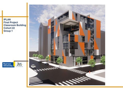
IPLAN Final Project Classroom Building Cohort 22 Group 1
Project Overview
OBC Analysis 2.1 Introduction 2.2 General Information 2.3 Building Occupancy 2.4 Building Classification 2.5 Occupant Load 2.6 Fire Separation and Fire Resistance 2.7 Exits and Egress 2.8 Exit through Lobby 2.9 Fire Alarm Systems 2.10 Fire Fighting Provisions 2.11 Standpipe and Hose System 2.12 Spatial Separation 2.13 Health Requirements 2.14 Mezzanine and Interconnected Floors 2.15 Barrier Free Requirements 2.16 Conclusion
1.1. Project Brief 1.2 Team 1.3 Approach and Work Strategy 1.4 Timelines and Meetings 1.5 Site and Urban Context 1.6 Site Analysis and Design Intent 1.7 Program Allocation
Materials and Methods Analysis 3.1 Introduction 3.2 Structure 3.3 Building Envelope 3.4 Façade Materials 3.5 Green Roof
BIM Analysis 4.1 Introduction 4.2 Process 4.3 Project Development 4.4 Visualization 4.5 BIM 360 Challenges 4.6 Conclusion
Conclusion References Appendix
1.1 Project Brief 02 The project was to design a classroom building on the Ryerson campus. The brief defined the building to be in concrete, clad with fiber cement panels as a rain screen system.
Wala Ibrahim OBC Lead
The goal of this assignment was to create a building designed to • illustrate compliance to the OBC. • use the given materials and methods and exhibit the proper use of technology • illustrate these concepts utilizing Revit. • synthesize the concepts taught in the IPLAN program and to be able to successfully express these them in both presentation and written format.
Wala Ibrahim
1.2 The Team
Vandana Prakash Materials Lead
We are a team of five internationally trained architects participating in cohort 22 of IPLAN, a bridging program provided by JVS and Ryerson University. With diverse experiences from Sudan, Ethiopia and India, along with the knowledge and skills gained in OBC, Materials and Methods and Revit, we were able to collaborate successfully to complete this final integrated project.
Ridhi Shah BIM Lead
Each member of the team was a lead of a section and responsible for its design. This report is a result of strong teamwork skills, collaborative workshops, dedicated schedules and timelines and intense research and analysis. Nevertheless, we worked in close collaboration on all aspects of design to develop this project.
Fitsum Berhe BIM Lead CLASSROOM BUILDING
01. INTRODUCTION
Harsimran K Arora Project Lead
Project Background & Overview
June29-july6
July 20-27
Practice run WEEK 5 July 27-Aug 3
4. Revit Work-sharing: That information was then implemented to a 3d model.
Phase 6- compilation
WEEK 4
3. Designing and Planning: Vigorous brainstorming was done in workshops to plan layouts in compliance to the codes and fit in the defined program. Designing elevations as per the code was completed.
Phase 5-detailing the model
Draft report
Phase 4- Revit
July 13-20
2. Research, study and calculations: The next steps were OBC calculations and compiling codes affecting the building. Also, data on materials was conducted to understand assemblies and structure.
Phase 3-designing
WEEK 3
1. Site: A site visit and analysis was conducted to have a better understanding of the surroundings.
5. Detailing the model: Assemblies and materials then were added to Revit as researched and calculated to achieve the desired thermal and sound insulation. 6. Compilation: The last step was to prepare a report and presentation to demonstrate the learning
1.4 Timelines and Meetings We had regular meetings and collaborative workshops to implement data collected on the OBC and materials. With different perspectives, team members brought to the table diverse solutions to challenges faced in integrating codes and materials with design. Meeting agendas were passed on before the meetings and every topic was discussed as scheduled. Meetings were concluded by collectively laying down the next steps for every member and scheduling the next meeting. Timelines were laid out to achieve the milestone submissions and were respectfully followed
WEEK 6 Aug 3-10
Final presentation CLASSROOM BUILDING
01. INTRODUCTION
July 6-13
Phase 2-research and calculations
WEEK 2
03
The approach to the project was divided into 6 phases. All sections were undertaken concurrently in phases.
Phase 1-site
WEEK 1
1.3 Approach and Work Strategy
04
1.6 Site Analysis and Design Intent
▪
▪ The skyline of the neighbourhood expresses mostly high-rise and mid-rise buildings. The site is overshadowed by a high-rise on the eastern façade. The neighboring highrise buildings along with Allen Gardens and green spaces such as Ryerson Community Park assist in reducing the heat island effect. ▪ The site is zoned as institutional education. Identifying the neighbourhood as predominantly residential and commercial, the heart of the neighborhood contains many intuitional buildings belonging to Ryerson University. Being at the main intersection, the site serves as an onset to the campus, the idea was to design a landmark for Ryerson. ▪ Gerrard Street is a heavy traffic street. Having an advantage of accessibility on all sides, loading and parking access was provided through the internal lane on the west.
▪ ▪
▪
The site is located at the intersection of 101 Gerrard Street east and 111 Mutual Street East in downtown Toronto Ward 13.The 13m &12m wide main streets are along the north and the west façade. It also shares 6m wide concrete lanes with adjacent buildings which allows it to be accessible from all facades. There are two existing Ryerson buildings on the site- Cooperative Education building and Graduate Studies building but for the assignment it is a vacant plot. The setbacks of the plot are 2m from the north on Gerrard Street ,1m from the west on Mutual Street, 2m from the east and 3m on the south.
Heavy traffic Gerrard street
High rise overshadowing Ryerson University buildings the eastern facade
towards the west of the site
6m lane
Mutual street
Gerrard street
6m lane
sun path
Existing site with two Ryerson buildings
Site at the intersection of 13 m Gerrard Street and 12m wide Mutual Street
6m wide internal windows in concrete
11:00 AM
4:30 PM
SITE
Jarvis St Baptist Church
CLASSROOM BUILDING
01. INTRODUCTION
1.5 Site and Urban Context
Elevations
Green roof and mechanical room
Elevations designed to break the monotony of simple glass glazing, by using patterned fibre cement panels. The play between complete solid panel and solid cut into half angles sharply contrast the promenade to strike a sense of magnetism. Also the use of ochre colour makes its symbolic to Ryerson with its logo colour.
7th Floor Offices for admin & professional teaching staff: private offices, workstations. Lightwell cut-out into 6th floor 5th & 6th Floors Faculty rooms & staff support: private offices, workstations, lounges, meeting rooms, webinar rooms, copy room , IT room, storage. Lightwell from the 7th floor.
2nd , 3rd & 4th Floors Classrooms: 16 seat classrooms, 30 seat classrooms, breakout rooms. Mezzanine Lounge and resource center
West Elevation
1st Floor Entrance and Reception: Reception, reception workstations,100 seat classroom, food service, waste recycling room 4 storey Basements Parking: 96 car parking with 4 barrier free parking, mechanical rooms, custodial &, long term storage, storm water collection.
North Elevation CLASSROOM BUILDING
05
01. INTRODUCTION
1.7 Program Allocation
Ontario Building Code 06
2.5 Occupant Load
The building is designed to comply with the latest amended version of the Ontario Building Code. To navigate the building code, a road map was determined. As per Clauses 1.1.2.1.(1)&(2) and Sub-clauses 1.1.2.2.(1)(a)(i) & (b)(ii) the Parts 1,7,12,3,4,5 and 6 shall be applied.
Occupant load for classrooms is calculated as per Sub-clause 3.1.17.1.(c)(i). Occupant load for offices and food services is determined as per Table 3.1.17.1. Refer to table 2. Space
Occupanc Net Area/ Occupant Code y Sq. m Load Reference Type
2.2 General Description Site area: 1248 .3 sq. m Building Area: 986.9 sq. m. As per Article 1.4.1.2 Defined Terms - Building area Gross Area: 6460 sq. m. As per Article 1.4.1.2 Defined Terms-Gross area Building Height: 7 storeys . As per Article 1.4.1.2 Defined Terms - Building Height.
Classrooms
A2
2102
795
3.1.17.1.(c) (i)
Food Services
A2
141
128
Table 3.1.17.1
Offices
D
876
94
Table 3.1.17.1
3119
1017
Total
Figure 1. building occupancy in each building’s floors. Table 2. Occupant load per spaces
2.3 Building Occupancy The building has a major occupancy of Group A Division 2 Assembly occupancy, subsidiary occupancy of Group D Business and Personal Services, and Group F Division 3 Low Hazard Industrial use. As per Tables 11.2.1.1.C, 11.2.1.1.J and 11.2.1.1.M. Refer to Figure 1
2.4 Building Classification According to the project height and area, the building is classified as per Article 3.2.2.23 Group A Division 2 Any Height Any Area, which requires the building to be sprinklered and noncombustible. Refer to table 1
Element
Fire Separation
Fire Resistance
Construction Type
Sprinklered
Code Reference
Floors
Yes
2 hr
Noncombustible
Yes
Article 3.2.2.23
Mezzanine
No
1 hr
Noncombustible
Yes
Article 3.2.2.23
Columns
-
2 hr
Noncombustible
-
Article 3.2.2.23
Roof
No
N/R
Noncombustible
-
Article 3.2.2.23
Table 1. Building classification
CLASSROOM BUILDING
02. OBC ANALYSIS
2.1 Introduction
07
2.6 Fire Separation and Fire Resistance
02. OBC ANALYSIS
As per articles 3.1.3.1 and 3.3.1.1 fire separation and fire resistance between building occupancies has been determined. In addition, fire separation is required around the exit stairs, elevator hoist-way and service room shafts. Refer to table 3.
Figure 2. Fire separation and fire resistance
2.7 Exits and Egress 2.7.1 Number of Exits Number of exits is determined upon Table 3.3.1.5B egress For Sprinklered Floor, giving that area of classrooms is more that 200 sq. m and offices is more than 300 sq. m 2.7.2 Distance between Exits Building diagonal is 43 m, as per Clause 3.4.2.3.1.(b) the distance between exits shouldn’t be less than 9m. Figure 5 & 6 2.7.3 Location of Exits As required by Clause 3.4.2.5.1(b) &( c ) the travel distance to any of the exits shouldn’t exceed 40 m in offices and 45 m in occupancies other than high hazard industrial occupancy. Refer to figure 3 & 4.
Figure 3. Travel distance in level 1. Element
Fire Resistance
Enclosure Table 3.1.8.4
Code Reference
A2-D
1 hr
45 min
Table 3.1.3.1
A2-A2
1 hr
45 min
Sentence 3.3.1.1.(1)
D-D
N/R
-
Sentence 3.3.1.1.(1)
Exits
2 hr
1.5 hr
Sentence 3.4..4.1.(1)
Elevator shaft
1.5 hr
1 hr
Table 3.5.3.1
Mechanic-al shaft
1 hr
45 min
Table 3.6.3.1
Table 3. Fire separation between occupancies
Figure 4. Travel distance in level 5.
CLASSROOM BUILDING
2.7.4 Exit Width
2.9 Fire Alarm system: The building shall include two stage fire alarm system complying with Clause 3.2.4.1.(1).(C) & (d) and Clause 3.4.2.3.(1).(e)
2.9.1 Fire Department connection: Complying with sentence 3.2.4.15.(1) , a fire department connection for the standpipe system shall be provided within 45m from nearest fire hydrant.
2.10 Fire Fighting Provision:
Figure 6. Handrail
2.8 Exit through lobby: Figure 5. Exit stair width
2.7.5 Handrail: A handrail on both sides of the stairs with a height of 900 mm is provided, complied with Sentence 3.4.6.5.(1). And Clauses 3.4.6.5.(5).(a) &(b). Refer to figure 6
Exit through lobby is provided, fulfilling the criteria required by Article 3.4.4.2, floor area is sprinklered, path of travel not more than 15m to outdoor and lobby is not in an interconnected area. Refer to figure 7
The building is sprinklered , therefore it is not required to comply with Articles 3.2.5.1 access to above grade storeys and 3.2.5.2 Access to basements. The building roof is accessible by staircase complied with Clause 3.2.5.3.(1)(a) Access route for fire department vehicle is provided for the building complying with Clause 3.2.5.4.(1)(a) located at the principal entrance of the building.
2.7.6 Risers and Treads:
2.11 Standpipe and Hose System:
Riser and treads are designed as per coming amendment in 2022 in Sentence 3.4.6.8.(1)& (2). Maximum riser is 180 mm and tread is not less than 280 mm.
The building shall include a standpipe system , as it is more than 3 storeys in height complying with Clause 3.2.9.1.(1)(a)
2.7.7 Direction of Door Swing: Exits doors swing in the the direction of travel as per Clause 3.3.1.10.(2)(a)
Figure 7. Exit through lobby
CLASSROOM BUILDING
08
02. OBC ANALYSIS
As required by 3.4.3.2.(1)(b), the exit stair width for an assembly building should be 8 mm per person. Maximum occupant load per floor is 260 persons. Required exit width is (260 x 8=) 2080mm. Two exits are provided; each exit width should be 1040 mm. However, the minimum required exit width is 1100 mm as per 3.4.3.2.(7)( c). Refer to figure 5.
2.12 Spatial Separation and Unprotected Openings
As per Article 1.4.1.2, the definition of limiting distance is taken from the center of the street in the north and west elevation, and the center of the lane in the east and north elevation. The exposed building façade is calculated level by level and UPO percentage is determined as per Table 3.2.3.1.D. Unprotected openings are limited for buildings or fire compartment that are sprinklered. Fire resistance of façade is determined as per Table 3.2.3.7. the building is required to be of non-combustible structure as per Article 3.2.2.23 , therefore type of façade construction and cladding also comply. Refer to table 4 and figure 8.
Figure 8. Unprotected openings
LD/m
EBF/sq. m
UPO%
allowed
provided
FFR
Code Reference
North
11.8
998.1
100%
48.50%
N/R
Table 3.2.3.1.D.
South
6
1035
70%
38.80%
45 min
Table 3.2.3.1.D.
East
5
1040
55%
45%
45 min
Table 3.2.3.1.D.
West
9.5
1127
100%
45.60%
N/R
Table 3.2.3.1.D.
Table 4. Unprotected openings calculations
2.13 Health Requirements Number of required washrooms is calculated as per occupant load for each floor in reference to Table 3.7.4.3 A & 3.7.4.3 D for assembly occupancy and Table 3.7.4.7 for offices, considering 14 sq. m per person as required by Sentence 3.7.4.2.(1). Two thirds of male washrooms are replaced by urinals as per Clause 3.7.4.2.(3)(b). Three barrier free washrooms are required as per Table 3.8.2.3A. Refer to table 5 Level
Code Reference
1st Floor
3
5
1
-
Tables 3.7.4.3 A &D, 3.7.4.7, 3.8.2.3.A
2nd Floor
3
5
-
1
Tables 3.7.4.3 A &D, 3.7.4.7, 3.8.2.3.A
3rd Floor
3
4
1
-
Tables 3.7.4.3 A &D, 3.7.4.7, 3.8.2.3.A
4th Floor
3
4
-
1
Tables 3.7.4.3 A &D, 3.7.4.7, 3.8.2.3.A
5th Floor
3
2
1
-
Tables 3.7.4.3 A &D, 3.7.4.7, 3.8.2.3.A
6th Floor
3
2
-
1
Tables 3.7.4.3 A &D, 3.7.4.7, 3.8.2.3.A
7th Floor
-
-
1
1
Tables 3.7.4.3 A &D, 3.7.4.7, 3.8.2.3.A
Table 5. Washroom count
CLASSROOM BUILDING
09
02. OBC ANALYSIS
Percentage of unprotected openings in the building is subject to the limiting distance and exposed building façade.
Elevations
2.14 Mezzanine & Interconnected Floors
The building is required to comply with all barrier free requirements as per Sentence 3.8.1.1.(1). Refer to table 6 which Shows barrier free application considered in the building. Element
Requirement
Code Reference
Entrance
1 pedestrian entrance is required to be barrier free
Table 3.8.1.2
Path of travel
Unobstructed path of travel not less than 1600 mm
Sentence 3.8.1.3.(4)
Barrier free washrooms
1 barrier free washroom is required in each 4-9 washroom stall
Table 3.8.2.3. B
Universal Washrooms
3 plus universal washrooms for over 6 floors
Table 3.8.2.3. A
Doorways
All doors in path of travel have clear width of 860 mm
Sentence 3.8.3.3.(1)
02. OBC ANALYSIS
Mezzanine area was determined as per Clause 3.2.1.1.(3)(a) , 40 % of the open area of first floor. Refer to figure 8 & 9 Figure Interconnected floors are provided in different parts of the building. Between Mezzanine and third floor with a cut out on slab less than 20 m2 complied with City of Toronto requirements and no fire separation is required. 6th and 7th interconnected floors have a cut out with area of 112 m2 , sprinklered glass is provided around the cut out. Refer to figure 10
10
2.15 Barrier Free Design
Table 6. Barrier free requirements
2.16 Conclusion: The building is complied with latest amendment of Ontario Building Code, and that shaped some of building fundamentals such as : Construction type: Non-combustible structure Façade design: fenestration percentage, and Space planning: Dimensions and fire separation between spaces. Figure 8. Mezzanine plan
Although the restrictions that Building Code imposed to avoid fire hazard such as interconnected floors, mechanical solutions such as sprinklered glass is provided to meet client’s requirements. Figure 9. Mezzanine view
Figure 10. Interconnected floors
CLASSROOM BUILDING
Materials & Methods 3.1 Introduction
11
Green roof - Improvising the microclimate
Skylight - daylight into the building
Building
Exterior walls Metal stud wall Rain screen system cladded with cement fiber panels
Concrete slab supported with concrete beams & columns
Building Materials play a significant role in achieving an equilibrium between aesthetics and practicality of the structure while withstanding the harsh weather constraints. Our design approach is to provide student centric & barrier free spaces in a seven-storey classroom building, our focus was to provide a well lit and well-ventilated interior space, reducing the usage of artificial lighting during maximum hours of the day making it energy efficient building. The most important aspect in protecting the built form is to have a series of climatic barriers both internal & external to protect the structure against any type of failure. These components and barriers in the right proportion provide an insulation and the desired R value rating to the built form creating a comfortable environment for the inhabitants.
Raft foundation Slab on grade
Figure 01. Building envelope details Components
Double glazed tempered glass panels
R-Value
Roofs
R-25 ci
Walls
R-13 + R–13 ci
Walls below grade
R–10 ci
Floors
R–12.5 ci
Slab on grade
R–10
Vertical fenestrations
0.35
Skylight
0.36
Figure 02. Minimum requirement of insulation as per SB-10
Figure 03. Zones As per MMAH SB-10 our site is Zone 5 based on the heating degree-days of 3520 as per MMAH SB-01
CLASSROOM BUILDING
03. MATERIALS & METHODS
Structure Building Envelope Skeleton Skin Beams, Columns & Exterior walls, slabs roof & slab on grade - Strength & - Aesthetics Stability - Physical separator
3.2 Structure Soil type: The site is located in the heart of Toronto’s downtown near lake Ontario.
Figure 04. Geological map
As per our analysis of the geology of this area, it contains Lake Iroquois soil, sand and silt sand with a shallow water deposit. Soil having a water table at a depth higher than the foundation level will have low bearing capacity (capacity of soil to support the loads applied to the ground) This type of soil has a tendency to retain moisture; the soil is cold and drains poorly. This causes the silty soil to expand, putting pressure against the foundation and weakening it, which is not ideal to support a foundation. Hence the buildings in such soil must be well reinforced & waterproofed
Retaining Wall : Walls in the basement have been constructed with 200 mm CMU protected with rigid insulation, damp proofing and a waterproofing system.
12
Figure 06. Structural layout
Columns: 300mm x 700mm Varying grid to accommodate the spaces. Floating columns: 300mm x 450mm in the 6th & 7th floors Beams: 300mm x 700mm including the slab thickness Slabs: 200mm thickness 2- way slabs with varied spans as per the column grids.
Retaining wall Lift shaft Cement screed Rigid Insulation Raft foundation beams Raft foundation base slab Slab footing Lift pit Lift pit footing Figure 05. Raft foundation detail
CLASSROOM BUILDING
03. MATERIALS & METHODS
SITE
Foundation: As we are proposing to construct a building having a mass that is seven storeys above grade and four storeys below grade in this type of soil, the building requires a stable foundation. We decided to build with a raft foundation which would give more stability to the structure and reduce the load on the soil as this building floats on the ground as a raft floats on water. There is a 200mm of concrete slab extending over the entire building stiffened by 600mm x 400mm of inverted beams with an infill of rigid insulation covered with 75mm of floor screed.
3.3 Building Envelope:
13
Components
Metal cap flashing Cap sheet mod bit roofing membrane Flexible membrane Base sheet modbit roofing membrane High density cement fiber panels Mineral fiber rigid insulation Air / Water barrier OSB
Thickness
R-Value
Interior Type X gypsum board
16 mm
0.56
Metal studs with batt insulation
152mm
13.00
Exterior grade gypsum sheathing
16mm
0.56
Batt insulation between metal studs Vapour barrier Type X gypsum board
Self adhered Air/Vapor barrier
40mils
0.01
EXP insulation
Mineral fiber insulation
76mm
12.6 ci
Vapor Retarder
Air space
38mm
1.00
Concrete Slab
Fiber cement cladding
8mm
0.38
2° slope
Figure 08. Roof to wall junction detail also showing the parapet wall detail
Table shows R values and thickness for the materials
High density cement fiber panels Air gap with Z channel to fix the cement fiber panels Mineral fiber rigid insulation Air / Water barrier OSB Type X gypsum board Vapour barrier Batt insulation Light metal framing Wooden flooring Furring purlin Extruded polystyrene Insulation Concrete floor slab
Basement retaining wall Air / Moisture barrier Ddrainage mat Rigid Insulation Cement screed Insulation Foundation base slab Damp proofing membrane
Figure 07. Floor Slab to wall junction detail
Figure 09. Slab on grade and retaining wall junction detail
Rigid Insulation Layered gravel Weep tile Raft foundation & wall footing
CLASSROOM BUILDING
03. MATERIALS & METHODS
Building Façade: We aimed to beautifully blend different materials and textures in the façade detailing, by having solid opaque cement fiber panels which contrasted with the glazing, creating a seamless visual connect between the interior & exterior spaces.
3.4 Façade Material
14
Cement Fiber Panels:
Advantages of fiber cement products • Maximum protection against weather •Excellent longevity • Easy installation in any climate • Almost no maintenance required • No cracks, paint or sealant problems • High sustainability • Noncombustible Lightweight panels and joints deflect most of the rainwater Ventilated cavity eliminates the remainder of the moisture by natural drainage and evaporation
Glazing Figure 11. Rainscreen working system Air cannot exit Closed at top
Air enters Open at bottom
Figure 12. Typical idea of the rain screen system
Glazing :
High density cement fiber panels
Building façade has an extensive use of doubleglazed fritted panels. Low E, tinted, fritted glass of helps in reducing glare, lowers the danger to birds.
Air gap with Z channel to fix the cement fiber panels
Provides better insulation value. Increases acoustical control. It creates an interesting visual interfaces between the interior and exterior. Light when passed through these patterns it creates a dramatic play of light and shadows in the interior spaces.
Figure 10. North Elevation
03. MATERIALS & METHODS
Cement fiber panels - Rain screen system
Fiber cement is a composite material with a cement base reinforced with cellulose fibers.
Mineral fiber rigid insulation
Figure 14. Double glazing U-value : 0.25 R-value : 4 Heat from sun passes into the room
Heat from room refracted back due to the coating
Air / Water barrier OSB Light metal framing Batt insulation Vapor barrier Type X gypsum board
Figure 15. Cement fiber panel fixing detail
Figure 13. Exterior wall assembly
CLASSROOM BUILDING
3.5 Green Roof System
Figure 16. Perspective of the proposed Skylight and green roof
Figure 17. Sectional perspective of proposed Skylight and green roof
Vvegetation Vegetation blanket Filter fabric Drainage layer Filter fabric Rigid insulation Root barrier Separation sheet Roofing membrane Concrete roof slab Figure 18. Green roof assembly
CLASSROOM BUILDING
03. MATERIALS & METHODS
The green roof, as an insulation system made of natural local materials, took shape in a variety of vernacular architecture. • It’s a complex layered system that helps in the better performance of the building along with giving an aesthetically pleasing appearance. •Green roofing system improves the Macro climate & urban ecosystem •vegetation and layers composition benefits the quality of life by delaying peak flood while retaining rainwater, reducing CO2 while producing oxygen and recreating biodiversity. •Reduce pollution, water retention. •Reduces heat island effect in urban areas. •Extends roof lifespan by reducing daily temperature fluctuations and provides shading from ultraviolet light. •Provides energy savings from additional insulation & evaporative cooling.
15
BIM Analysis 16
4.1 Introduction
Another important step was linking both 2D and 3D AutoCAD files to the project which helped us to facilitate the initial design process. We linked some rough design ideas and sketches in addition to the 3D massing of the surrounding area acquired from the City of Toronto website .
BIM/ Revit
BIM Lead
Setup
BIM Lead collaborate with each team members Design development - Site Context - Design Program - Application of the research Data from OBC & Material and Methods Collaboration
Work-sharing
BIM Lead + Each Team member
-
Production of drawings Plans, Elevations, details, 3D Models In-house Production
Communication Figure 2.. Stages of the design process
The next stage was the collaboration-work-sharing part of the deign process, where all members of the team participated on the Revit design model while conducting the research on requirements of OBC, Material and methods, and the Revit software itself. With continuous communication among all team members, we collaborated in developing the design working on the same model at the same time. The last stage was the in-house production where we produced various architectural drawings such as; plans sections, elevations, details, and visualization Figure 1. Potentials of BIM
CLASSROOM BUILDING
04. BIM A NALYSIS
We started the design aspect of our BIM process by setting up the Revit platform organized by the BIM leads. This setup stage consisted of some basic and important settings within the Revit file such as adjusting project unit, creating levels, creating work sets and so on. After that we uploaded the file to the cloud-based collaboration and work-sharing platform formerly known as Autodesk BIM 360 recently rebranded as Autodesk construction cloud.
We used BIM in creating an integrated building design through information management, collaboration, and work-sharing among the team members. Using Revit as a BIM tool facilitates in creating a platform for each team member to work collaboratively but at the same time work independently. With the help of Revit cloud work-sharing, each team member was able to work on the same model at the same time, maintaining proper communication.
4.2 The process
17 Creating Levels
4.2.1 Setup Linking AutoCAD
Figure 03.. Levels and imported 2D AutoCAD file
This setup stage was mainly coordinated by the BIM-Revit team leads to reduce errors related to such as; working on the wrong level, duplication of linked files, and work sets
We have started the collaboration and work-sharing by fixing some of the design elements those could be taken as datum. At the early stages of the design there were different ideas on the functional layouts. After discussions on the location for the core, the BIM team leads fixed the core (vertical circulations) so that all team members can work of developing the functional layout and other aspects of the design. To achieve the best result out the collaboration on the same model, we decided to use the combination of two methods. The first one is each member of the team works on separate levels of dealing with such as; functional layouts, furnishing, and finishing materials
Figure 06. Uploading file to BIM 360
Figure 07. Fixing core
Figure 04. Linked 3D AutoCAD file
Figure 05. Work set creation
Figure 8. Working on different floor levels and work sets
Sharing some Revit tool tips among the team The second method was working on different work sets. In this case one team members members helped considerably in acquiring focuses on one single work set but with continues to review other members’ work. Some of common understanding on using the software these work sets we created were the structural system, core and the facade design. when working on the same model. CLASSROOM BUILDING
04. BIM A NALYSIS
Creating Work sets
4.2.2 Collaboration / Work-sharing
OBC
18
4.3 Project development: Tools and elements
4.2.3 Production Revit
Load Family
Edit Type
• •
Duplicating the original wall type Adding core, substrate, etc. with relative thicknesses
•
Stair
All furniture families were edited using this tool and were customized as per required sizes
• •
The staircases were grouped and then pasted at selected levels The arrow adjusts the risers, the dot adds/subtracts risers
Figure 09. Revit used for Path Travel tool and speed
Materials and Methods
Revit
Figure 10. Revit used for Displacement tool and calculation of R values
Displacement tool feature helped us create exploded views to demonstrate our use of materials on the façade. Also R values were fed in properties while wall assemblies were created for each wall type, to calculate the R value of the whole assembly.
Figure 11. render of interiors expressing different elements of Revit used during the process
CLASSROOM BUILDING
04. BIM A NALYSIS
With the help of Path of travel tool and speed, we measured distances from the nearest exit to the corners of every room, to ensure that they are within the code requirements.
Modelling a complex building in Revit gave us an opportunity of understanding the building clearly and in more detail. It has lot of useful tools that allowed us to create a realistic building model.
4.4 Visualization
19
04. BIM A NALYSIS
Figure 12. Sectional axonometric showing tools and elements of Revit
CLASSROOM BUILDING
20
4.5 Challenges Façade deign
Work-sharing Challenges
Independent elements Created on each floor
Curtain wall with some panels converted to solid element
Edit Profile tool
Work-sharing allowed all members to use the same file at once and coordinate seamlessly. However there were some challenges involved with it. The software needed to be synchronized regularly and sometimes the process became very slow when trying to grant for access and that made us lose time in design. To avoid this issue we made sure we synchronized with central file and relinquished the ownership more often. Sometimes the model would give error lowering the speed as the project got more detailed and heavy. Since Revit persists the model in cloud, we encountered difficulties such as very slow data transferring. To speed up the workflow, we tried to work in turns.
Figure 13. Facade design experiment
As shown in figure 13, we tried different methods and tools. Finally, we explored a better one that suits our design. This is done using a curtain wall tool hoisted on to a solid wall and further editing the profile of the curtain wall in the desired pattern. This method gave us a continuous curtain and solid wall elements having a separate area calculation parameters. In addition, it is possible to dismantle these two elements separately without affecting their individual shapes. Furthermore, finishing materials can be applied to the solid wall elements by splitting the surface into smaller panels.
4.6 Conclusion BIM 360 has been a great software that allowed us to continue to be efficient and work remotely as an impact of Global Pandemic. Apart from a few challenges that we faced, the outcome was satisfactory and we were able to create a high quality project with a set of drawings and visual effects.
CLASSROOM BUILDING
04. BIM A NALYSIS
Our idea of creating a facade with a combination of solid, transparent and void elements to break down the big mass into smaller elements was on of the challenges. Moreover, we wanted these elements to have an independent character but at the same time coexist. These characters helped us in the UPO calculation, and the application of materials, and while using the displacement tool to create some graphical models.
Conclusion
21
Being Internationally trained architects, it was a unique opportunity for us to use our diverse skills and knowledge, and work in cohesion. The Ontario Building Code and Materials & Methods were the drivers of our design and Revit was used to demonstrate our understanding of these subjects.
Materials and Methods brought to light how to correspond construction methods with the building codes.. The permissible percentage of the Unprotected Openings helped us design and assess different materials accordingly. The selection of materials for the wall assemblies was carefully considered. R values were calculated for all materials, that gave us the total R value of the wall, roof and other assemblies. The assignment helped us explore innovative qualities of simple materials such as fiber cement panels and concrete. Revit helped us execute OBC and Materials & Methods. It acted as a generator of our design and spaces. Work-sharing and collaboration on BIM 360 was challenging at the beginning. However, with better organization and management, constant communication, the process was much smoother. Designing the envelope was one of the challenges. Each one of us sharpened our skills in Revit by pushing our limits and overcoming trouble shooting issues. We all got hands-on experience by being a part of the back-and-forth process, amidst different areas of Revit, which is used intensively in Architectural practice today. It was indeed a wholesome experience to collectively work on the classroom building through the spectrum of all three courses learnt in the program.
CLASSROOM BUILDING
05. CONCLUSION
The 2020 edition of Ontario Building Code permits the use of noncombustible material which is sprinklered for group A2 – Assembly occupancies. With the aim of meeting the requirements of OBC, the client’s program has been subjected to a few modifications. Some of the many things we considered are exit widths, travel distances, barrier free circulation, water closets, and an exit through the lobby. Thanks to the knowledge we gathered through the program, we were able to decode, analyze and design a structure which was legal and code compliant.
References
22
5.1 Books & Legal Documents
5.2 Websites Mid-Rise Buildings – City of Toronto Search GeologyOntario (gov.on.ca) Maps – City of Toronto LEEsystem | U.S. Green Building Council (criticalconcrete.comD rating) Fire Rated Gypsum (certainteed.com) The insulation building code 2021 | Ecostar Insulation building_manual_ap_1.pdf (ahfc.us) Tables for Calculating Effective Thermal Resistance of Opaque Assemblies (nrcan.gc.ca) Concrete Walls_EN.pdf (tboake.com) Wall Footing Section with "fiber Cement Board" Cladding. There is a basement. - CAD Files, DWG files, Plans and Details (planmarketplace.com) Panels | The Building Enclosure (wordpress.com) Health Dashboard - External prd (autodesk.com) Help - Revit Forum
5.3 Credits David Hine- OBC Instructor, Ryerson University Patrick Saavedra- Materials & Methods Instructor, Ryerson University Sean Robbins- Revit Instructor , Ryerson University Philip Hollet- IPLAN program Manager,JVS toronto Diane Brockman- Program Facilitator, JVS Toronto Andrew Aziz- Teaching Assistant (Revit), Ryerson University
CLASSROOM BUILDING
05. REFERENCES
Ontario Building Code 2012 Building Construction Illustrated- by D.K.Ching Construction Handbook-Chudley MMA Supplementary Standard SB -10
Appendix OBC Matrix
05. APPENDIX
CLASSROOM BUILDING
OBC Matrix
05. APPENDIX
CLASSROOM BUILDING
OBC Matrix
05. APPENDIX
CLASSROOM BUILDING
OBC Matrix
05. APPENDIX
CLASSROOM BUILDING
Net to gross area Ratio Calculation Floor area
Fire rating for external walls
Circulation Area
Percentage
Level 1
452.63 sq.m
944 sq.m
Mezzanine Level
197.464 sq.m
197 sq.m
Level 2
180.00 sq.m
944 sq.m
20%
Level 3
185.27 sq.m
968 sq.m
20%
Level 4
169.17 sq.m
968 sq.m
18%
169.17 sq.m
968 sq.m
18%
Level 6
260.39 sq.m
897 sq.m
30%
Level 7
346.19 sq.m
908 sq.m
38%
Total
1959 sq.m
6595 sq.m
30%
Levels Level 1 Mezz. Level 2 Level 3 Level 4 Level 5 Level 6 Level 7
Required FRR
North 1-1.02
Not Required Not Required
South 1-1.02
45 min
Combustible or Combustibleor Non Non Combustible Combustible
East 1-1.01
45 min
Combustible or NonNon Combustible Combustible
West 1-1.01
Not Required Not Required
47%
Level 5
Gross area 944 sq. m 197 sq. m 944 sq. m 968 sq. m 968 sq. m 968 sq. m 897 sq. m 908 sq. m
Net area 843 sq. m
6879.6sq. m
5186 sq. m
Construction Cladding Type Type
Façade L/H-H/L
764 sq. m 782 sq. m 799 sq. m 799 sq. m 637 sq. m 562 sq. m
CLASSROOM BUILDING
Not Required
Not Required
05. APPENDIX
Levels
Spatial separation calculation 11.8 6 5 9.5
UPO (Unprotected Openings) North 100% South 52% East 40% West 100%
11.8 6 5 9.5
100% 55% 40.70% 100%
11.8 6 5 9.5
100% 55% 40.70% 100%
11.8 6 5 9.5
100% 55% 40.70% 100%
11.8 6 5 9.5
100% 55% 40.70% 100%
Spatial Separation
Wall
Level 1(A2) Level 2(A2) Level 3(A2) Level 4(A2) Level 5(D) Level 6(D) Level 7(D)
Total
EBF ( Exposed Building Façade) North
156
140.4
140.4
140.4
140.4
140.4
140.4
998.4
South
156
140.4
140.4
140.4
140.4
140.4
140.4
998.4
146.25
146.25
146.25
146.25
146.25
146.25
146.25
146.25
146.25
146.25
146.25
146.25
East
157.5
West
157.5
1035 1035
100% 55% 40.70% 100%
11.8 6 5 9.5
100% 55% 40.70% 100%
Building Height Level 1 6m Mezz. 3m Level 2 4.5m Level 3 4.5m Level 4 4.5m Level 5 4.5m level 6 4.5m level 7 4.5m Total 33m Basements Basement 1 3m Basement 2 3m Basement 3 3m Basement 1 3m
CLASSROOM BUILDING
05. APPENDIX
LD (Limiting Distance) North 11.8 South 6 East 5 West 9.5
Interior and Exterior Finishes
05. APPENDIX
Interior finishes Components
Materials
Walls
Metal stud walls with batt insulation and Type X gypsum board
Floors
Concrete slab with extruded polystyrene insulation
Floor finish
• • •
Vinyl flooring Carpet Wooden floor finish
Ceilings
• •
Exposed ceiling False ceiling with acoustically perforated panels
Exterior finishes Components
Materials
Exterior façade
Fibre cement panels
Glazing
Fritted double glaa
Fritted Double glass
False ceiling with acoustical panels
Fiber cement panels
Metal stud wall with batt insulation with type X gypsum board
Wooden flooring
Carpet flooring
Tile flooring
CLASSROOM BUILDING
LEED -Sustainability Initiatives
Location and transportation Project is located on land that has been previously developed The site is not defined as sensitive land (Prime farmland, floodplains, habitat, water bodies, or wetlands
1 Point
LTc4 Surrounding Density and Diverse Uses
The site is located in Downtown Toronto and is surrounded by densely developed residential areas. The site is within walking distance to multiple publicly available diverse uses
5 Points
LTc5 Access to Quality Transit
The site is within proximity to multiple transit nodes including TTC buses, streetcar and metro A bus rapid transit stop: Less than 0.25 mile from 2 bus stops which are Jarvis street and Dundas Street at 0.2 miles and Jarvis street and Carlton which is 0.17 miles
5 Points
LTc7 Reduced Parking Footprint
Parking is less than minimum local code requirement thereby reducing the footprint associated with single vehicle use
1 Point
LTc8 Green Vehicles: Electrical parking
we provided 7 parking of total car parks for electrical vehicles
1 Point
Sustainable site SSp1 Construction Activity Pollution Prevention
provided specification on construction to avoid erosion and sedimentation
1 Point
SSc1 Site Assessment
site analysis is provided on the section of material and methods
3 Points
SSc4 Rainwater Management
rainwater is considered by providing catchment basins for rainwater and storm water tank in the basement
1 Point
SSc5 Heat Island Reduction
SSc5 Heat Island Reduction: green vegetated roof is provided for 50% of roof area to reduce heat island effect. Parking spaces are underground and solar panels are provided on mechanical penthouse to give a reflective roof
3 Points
CLASSROOM BUILDING
05. APPENDIX
LTc2 Sensitive Land Protection
LEED -Sustainability Initiatives Water Efficiency Landscape planted with native vegetation and requires minimal irrigation and maintenance. Landscape doesn’t require permanent irrigation beyond 2 years of establishment
2 Points
WEp2 Indoor Water Use Reduction
50% reduction in water consumption by using water conserving fixtures. All water fixtures are water sense labeled and water appliances and energy start labeled
6 Points
WEp3 Building-Level Water Metering
we applied 2 permanent sub metering for water end uses for irrigation and domestic use
1 Point
Energy and Atmosphere EAc1 Enhanced Commissioning
An individual commission agent will be appointed to conduct commissioning for mechanical , electrical and plumbing systems. The authority will a report a design review of the OPR, review contractor submittal. Building operation reviewed within 10 moths of substantial completion
6 Points
EAc2 Optimize Energy Performance
energy model will be conducted at detailed design phase. Will meet SB10 requirements. Walls and roof are properly insulated. Glazing area reduced to 45% of total wall area specifying efficient double wall glazing. Efficient HVAC equipment and water boilers would be installed. Efficient office equipment and LED lighting fixtures are installed
13 Points
EAc3 Advanced Energy Metering
It requires client decision and electric design to incorporate submeters. advanced energy metering for whole-building energy sources and individual energy sources that represent at least 10% of the total annual consumption are installed. All meters are capable of reporting hourly, daily, monthly, and annual energy use
1 Point
EAc5 Renewable Energy Production
PV generation will be provided on the roof top
1 Point
CLASSROOM BUILDING
05. APPENDIX
WEp1 Outdoor Water Use Reduction
LEED -Sustainability Initiatives Energy and Atmosphere (contd.) low impact refrigerant will be used as part of HVAC equipment's selection that minimize emission of compound that contribute to ozone depletion.
3 Points
EAc7 Green Power and Carbon Offsets
Green Power and Carbon Offsets: this will be deferred to design development phase and requires client decision
2 Points
Materials and Resources MRp1 Storage and Collection of Recyclables
recyclable storage room is provided on level 1
1 Point
MRp2 Construction and Demolition Waste Management Planning
demolition waste management plan will be implemented. specification will be provided to contractor
1 Point
MRc1 Building Life-Cycle Impact Reduction
option 4 , a LCA will be conducted during DD for the project structure and enclosure to demonstrate a minimum 10% reduction compared with a baseline building
5 Points
MRc2 Building Product Disclosure and Optimization - Environmental Product Declarations
we will specify that at least 20 different permanently installed products sourced from at least five different manufacturers that have an Environmental Product Declaration
2 Points
MRc3 Building Product Disclosure and Optimization - Sourcing of Raw Materials
we will specify that least 20 different permanently installed products from at least five different manufacturers that have publicly released a report from their raw material suppliers
2 Points
MRc4 Building Product Disclosure and Optimization - Material Ingredients
we will specify that least 20 different permanently installed products from at least five different manufacturers that demonstrate the chemical inventory of the product.
1 Point
MRc5 Construction and Demolition Waste Management
Will Divert minimum 75% of the total construction and demolition material using four material streams.
1 Point
CLASSROOM BUILDING
05. APPENDIX
EAc6 Enhanced Refrigerant Management
LEED -Sustainability Initiatives Indoor Environment Quality calculation will be conducted by mechanical engineer to demonstrate compliance with ASHRAE 62.1
1 Point
IEQp2 Environmental Tobacco Smoke Control
Signage will be provided prohibiting smoking within 7.5 m of building entrance
1 Point
IEQc1 Enhanced Indoor Air Quality Strategies
3 entry way grilles will be provided at building entrance
2 Points
IEQc2 Low-Emitting Materials
Specification of interior finishes to meet low VOC content requirements. Materials for flooring, walls, ceilings, thermal and acoustic insulation, composite wood, furniture, paints and coatings, adhesives and sealants will be complaint to CDPH standards
3 Points
IEQc3 Construction Indoor Air Quality Management Plan
Contractor will provide specifications to meet SMACNA guidelines
1 Point
IEQc4 Indoor Air Quality Assessment
testing/ IAQ testing will be provided after construction
2 Points
IEQc5 Thermal Comfort
Design HVAC systems and the building envelope to meet ASHRAE 55-2010, Thermal Comfort Conditions for Human Occupancy, with errata
1 Point
IEQc6 Interior Lighting
Providing induvial controllers for 90% and also for shared multi occupant spaces to enable adjustments that meet their need and preferences
2 Points
IEQc7 Daylight
Daylight model will be conducted during DD phase to assess the required daylight parameters . Double glazed fritted glass used to meet the lux level of sunlight exposure
3 Points
IEQc8 Quality Views
Analysis will be conducted at DD phase to assess achievement of 75% clear view for all regularly occupied floor area
1 Point
IEQc9 Acoustic Performance
acoustic analysis will be conducted at DD phase to select finishes with adequate acoustic performance . Sound attenuation will be provided to reduce background noise from HVAC
1 Point
CLASSROOM BUILDING
05. APPENDIX
IEQp1 Minimum Indoor Air Quality Performance
“I don’t think that architecture is only about shelter, it is about a very simple enclosure. It should be able to excite you, to calm you, to make you think”.
Zaha Hadid
CLASSROOM BUILDING
Gerrard St E Approx 13.0Mts wide
01
02
03
04
ENTRY
A1
EMERGANCY ENTRY
Green roof
Private property
6.0Mts wide side road
C1
ENTRY
Approx 11.0Mts wide
Mutual St
B1
Consultant Address Address Phone Fax e-mail No.
Description
Ryerson University
D1 Green roof
Classroom Building Site plan
E1 11032
Date
ENTRY
Project number Date
6.0Mts wide side road
1
Drawn by Checked by
Site plan 1 : 200
A100 Private property
Scale
1:150
01
02
03
04
A1 LIFT
LIFT
Lift lobby
Consultant Address Address Phone Fax e-mail
B1
No.
Description
Date
C1
Lift lobby
Ryerson University Classroom Building
LIFT
D1
Basement B1 floor plan Car lift 01
Car lift 02
Project number Date
E1
Drawn by Checked by
1
A101
Basement B1 floor plan 1 : 150
Scale
1:150
01
02
03
04
A1 LIFT
LIFT
Lift lobby
Consultant Address Address Phone Fax e-mail
B1
No.
Description
Date
C1
Lift lobby
Ryerson University LIFT
Classroom Building
D1 Car lift 01
E1
Car lift 02
Basement B2 floor plan Project number Date Drawn by Checked by
1
A102
Basement B2 floor plan 1 : 150
Scale
1:150
01
02
03
04
A1 LIFT
LIFT
Lift lobby
Consultant Address Address Phone Fax e-mail
B1
No.
Description
Date
C1
Lift lobby
Ryerson University LIFT
Classroom Building
D1 Car lift 01
E1
Car lift 02
Basement B3 floor plan Project number Date Drawn by Checked by
1
A103
Basement B3 floor plan 1 : 150
Scale
1:150
01
02
03
04
A1 LIFT
LIFT
Lift lobby
Consultant Address Address Phone Fax e-mail
B1
No.
Description
Date
C1
Lift lobby
Ryerson University LIFT
Classroom Building
D1
Basement B4 floor plan Car lift 01
Car lift 02
Project number Date
E1
Drawn by Checked by
1
A104
Basement B4 floor plan 1 : 150
Scale
1:150
Gerrard St E
Approx 13.0Mts wide
01
02
11090
03
8200
04
11000
ENTRY
A1 LIFT
Vestibule
LIFT
Work room
10300
Lift lobby Reception
Waiting room Lobby
Work room
EMERGENCY EXIT
Up
Food service
No.
Male W/c Barrier-free W/c
LIFT
6270
D1
Recycling
Garbage
Car lift 01
Classroom Building Main floor plan Project number
Car lift 02 EXIT
Classroom 100 Seating
Date Drawn by Checked by
ENTRY
1
A105
Main floor plan 1 : 150
Date
Ryerson University
Lift lobby Female W/c
E1
Description
Corridor 1.8 mts wide
Corridor 2.3 mts wide
FIRE EXIT
EXIT
5890 ENTRY
C1
8200
Mutual St
Approx 11.0Mts wide
B1
Consultant Address Address Phone Fax e-mail
Scale
1:150
01
02
03
04
---
A1
-
UP
---
Dn
B1 Up
Consultant Address Address Phone Fax e-mail No.
Longue
Description
Date
C1
Ryerson University LIFT
D1
Classroom Building Mezzanine Floor Plan Project number Date
E1
Drawn by
1
Mezzainine Floor Plan
Checked by
A105-A
1 : 150 Scale
1:150
01
02
03
11090
04
8200
11000
A1
Corridor 2.0 mts wide
10300
LIFT
60 Seating
B1
LIFT
Lift lobby
Break-out room
5890
Corridor 1.8 mts wide
Consultant Address Address Phone Fax e-mail No.
60 Seating
Description
Date
8200
Lobby Lift lobby
Corridor 2.2 mts wide
C1 60 Seating
Ryerson University Classroom Building
D1 Sencond floor plan 6270
Barrier-free W/c
Female W/c
E1
60 Seating
Project number Date
Male W/c
Drawn by Checked by
1
A106
Second floor plan 1 : 150
Scale
1:150
01
02
03
11090
04
8200
11000
A1 Corridor 2.0 mts wide
LIFT
10300
16 Seating 16 Seating
16 Seating Corridor 1.8 mts wide
Lift lobby
16 Seating
Corridor 2.5 mts wide
C1
Corridor 2.5 mts wide
5890
B1 16 Seating
LIFT
16 Seating
Consultant Address Address Phone Fax e-mail No.
Description
Date
8200
16 Seating Lift lobby 16 Seating
Ryerson University
Corridor 2.0 mts wide
Classroom Building
D1 30 Seating
Third floor plan
6270
16 Seating
Female W/c
E1
Barrier-free W/c
Male W/c
Project number Date Drawn by Checked by
1
A107
Third floor plan 1 : 150
Scale
1:150
01
02 11090
03
04
8200
11000
A1
16 Seating
16 Seating
Corridor 2.0 mts wide
10300
LIFT
16 Seating
16 Seating
Corridor 2.5 mts wide
Corridor 2.5 mts wide
5890
16 Seating
8200
Lift lobby
Consultant Address Address Phone Fax e-mail
B1
C1
LIFT
No.
Date
16 Seating
16 Seating
Lift lobby
Description
Ryerson University
16 Seating
Classroom Building
D1 6270
16 Seating
Fourth floor plan
30 Seating
Project number Female W/c
E1
Barrier-free W/c
Male W/c
Date Drawn by Checked by
1
A108
Fourth floor plan 1 : 150
Scale
1:150
01
02
03
11090
04
8200
11000
A1 LIFT LIFT
10300
Small staff lounge
Reception
LIFT LIFT
Lift lobby
Accessible terrace
B1
8200
C1
Corridor 1.8 mts wide
Corridor 2.5 mts wide
5890
Large meeting room
Consultant Address Address Phone Fax e-mail No.
LIFT
Ryerson University Classroom Building
D1 6270
Date
Lift lobby Webinar room
Barrier-free W/c
Fifth floor plan Drinking water
Male W/c
E1
Description
Female W/c
Copy room IT room
Project number Date Drawn by Checked by
1
Fifth floor plan 1 : 150
A109 Scale
1:150
01
02
03
11090
04
8200
11000
A1 LIFT
LIFT
10300
Lift lobby
Small staff lounge
Meeting room
C1
8200
Yueli director office
skylight ablove
Corridor 2.5 mts wide
Staff room Corridor 2.5 mts wide
5890
B1
Consultant Address Address Phone Fax e-mail No.
Ryerson University Classroom Building
D1 6270
Date
Lift lobby Lounge
Barrier-free W/c
Drinking water
Male W/c
E1
Description
Female W/c
Sixth floor plan
Yueli director office
EAP office
EAP office
EAP office EAP office
Project number Date Drawn by Checked by
1
A110
Sixth floor plan 1 : 150
Scale
1:150
01
02 11090
03
04
8200
11000
A1 LIFT
LIFT
Lobby
10300
Lift lobby
Consultant Address Address Phone Fax e-mail
8200
C1
skylight ablove
No.
Description
Date
Corridor 3.0 mts wide
Corridor 3.0 mts wide
5890
B1
Lift lobby
Ryerson University Classroom Building
6270
D1 Barrier- Barrierfree W/cfree W/c
Seventh floor plan kitchennete
Project number Date
E1
Janitor
drinking water
Drawn by Checked by
1
A111
Seventh floor plan 1 : 150
Scale
1:150
01
02
03
04
A1
B1
Consultant Address Address Phone Fax e-mail No.
Description
Date
C1
Ryerson University
D1
Classroom Building Roof plan Project number Date
E1
Drawn by Checked by
1
A112
Roof Plan 1 : 150
Scale
1:150
01
02
03
04 2 hr FRR Wall 1.5 hr FRR Wall 1 hr FRR Wall
A1
1.5 hr FRR door 1 hr FRR door 45 min FRR door
7m
18 m
FRR legend
20 m
1 : 150 35 m
5m
B1 33 m
1
5m
Consultant Address Address Phone Fax e-mail No.
Description
Date
.4 D 4
C1
m
15 m 17 17
m
m
Ryerson University Classroom Building
D1
Fire seperation -First Floor Project number
19 m
E1
Date Drawn by Checked by
1
FRR-1st Floor Plan 1 : 150
A119 Scale
1:150
01
02
03
11090
11000
17
A1
04
8200
2 hr FRR Wall
LIFT
1.5 hr FRR Wall 1 hr FRR Wall
LIFT
m Corridor 2.0 mts wide
31
m
1.5 hr FRR door 1 hr FRR door 45 min FRR door
10300
18 m
60 Seating
B1 5890
Corridor 1.8 mts wide
32 m 60 Seating
Lift lobby
FRR legend 1 : 150 Consultant Address Address Phone Fax e-mail No.
Description
Date
C1
D1 6270
Barrier-free W/c
Female W/c
Break-out room Male W/c
E1
Ryerson University Classroom Building
22 m
17 m
Lift lobby
60 Seating
m
8200
Lobby
43
Corridor 2.2 mts wide
35 m
60 Seating
32 m
Fire seperation-2nd Floor Plan Project number Date Drawn by Checked by
1
FRR-2nd Floor Plan 1 : 150
A120 Scale
1:150
01
02
03
04
2 hr FRR Wall 1.5 hr FRR Wall 1 hr FRR Wall 1.5 hr FRR door 1 hr FRR door 45 min FRR door
A1 23
FRR legend
m
1 : 150
m
Consultant Address Address Phone Fax e-mail
m
29
42
35 m
B1 33 m
21
C1
34
m
No.
Description
Date
20 m
m
25 m
19
1
6m
17 m
15 m
D1
m
30 m
Ryerson University Classroom Building Fire seperation- 5th Floor Plan Project number Date Drawn by
E1
Checked by
1
A121
FRR-5th Floor Plan 1 : 150
Scale
1:150
04
03
02
01 Roof Plan 35500 Mechanical Penthouse 33000
Seventh floor plan 28500
Sixth floor plan 24000
Fifth floor plan
Consultant Address Address Phone Fax e-mail No.
Description
Date
19500
Fourth floor plan 15000
Ryerson University Third floor plan
Classroom Building
10500
North elevation Second floor plan 6000 Level 1.5 Mezzanine 3000
Project number Date Drawn by Checked by
Main floor plan
1
North Elevation 1 : 150
A201
0 Scale
1:150
A1
B1
C1
D1
E1 Roof Plan 35500 Mechanical Penthouse 33000
Seventh floor plan 28500
Sixth floor plan 24000
Fifth floor plan
Consultant Address Address Phone Fax e-mail No.
Description
Date
19500
Fourth floor plan 15000
Ryerson University Third floor plan
Classroom Building
10500
West elevation Second floor plan 6000 Level 1.5 Mezzanine 3000
1
West Elevation 1 : 150
Project number Date Drawn by Checked by
Main floor plan
A202
0 Scale
1:150
01
02
03
04 Roof Plan 35500 Mechanical Penthouse 33000
Seventh floor plan 28500
Sixth floor plan 24000
Consultant Address Address Phone Fax e-mail No.
Description
Date
Fifth floor plan 19500
Fourth floor plan 15000
Ryerson University Third floor plan
Classroom Building
10500
South elevation Second floor plan 6000 Level 1.5 Mezzanine 3000
Project number Date Drawn by Checked by
A203
Main floor plan
1
South Elevation 1 : 150
0 Scale
1:150
E1
D1
C1
B1
A1 Roof Plan 35500 Mechanical Penthouse 33000
Seventh floor plan 28500
Sixth floor plan 24000
Consultant Address Address Phone Fax e-mail No.
Description
Date
Fifth floor plan 19500
Fourth floor plan 15000
Ryerson University Third floor plan
Classroom Building
10500
East elevation Second floor plan 6000 Level 1.5 Mezzanine 3000
Project number Date Drawn by Checked by
Main floor plan
1
East Elevation 1 : 150
A204
0 Scale
1:150
01
02
03
04 Roof Plan 35500 Mechanical Penthouse 33000
Seventh floor plan 28500
Sixth floor plan 24000
Fifth floor plan 19500
Fourth floor plan 15000
Consultant Address Address Phone Fax e-mail No.
Description
Date
Third floor plan 10500
Second floor plan 6000
Ryerson University
Level 1.5 Mezzanine 3000 Main floor plan
Classroom Building
0 Basement B1 floor plan
Project number
-5000 Basement B3 floor plan
Date
-7500 Basement B4 floor plan
Drawn by
-10000
1
Section 01
-2500 Basement B2 floor plan
Checked by
A301
Section 1-1 1 : 200
Scale
1:150
01
02
03
04 Roof Plan 35500 Mechanical Penthouse 33000
Seventh floor plan 28500
Sixth floor plan 24000
Fifth floor plan 19500
Consultant Address Address Phone Fax e-mail
Fourth floor plan 15000
No.
Description
Date
Third floor plan 10500
Second floor plan 6000
Ryerson University
Level 1.5 Mezzanine ---
3000
Classroom Building
Main floor plan
0 Basement B1 floor plan -2500 Basement B2 floor plan
1
1 : 200
Project number
-5000 Basement B3 floor plan
Date
-7500 Basement B4 floor plan
Drawn by
-10000
Section 2-2
Section 02
Checked by
A302 Scale
1:150
Consultant Address Address Phone Fax e-mail No.
Description
Date
Ryerson University Classroom Building Exterior Perspective Project number Date Drawn by Checked by
Exterior Perspective
A401 Scale
1:150
Consultant Address Address Phone Fax e-mail No.
Description
Date
Ryerson University Classroom Building Exterior Night View Project number Date Drawn by
Exterior Night View
Checked by
A402 Scale
1:150
Consultant Address Address Phone Fax e-mail No.
Description
Date
View of the entrance lobby
Ryerson University Classroom Building Interior Views Project number Date Drawn by Checked by
A405 View from the mezzanine
Scale
1:150
Consultant Address Address Phone Fax e-mail No.
Description
Date
View of the classroom
Ryerson University Classroom Building Interior Views Project number Date Drawn by Checked by
A406 View from the meeting room in the 6th floor
Scale
1:150