DECAY AND DEPLOYMENT
AUTOMATED MANUFACTURING OF NATURAL RUBBER IN DEGRADABLE AND ADAPTIVE BUILDING SKINS
Harry Hinton-Hard
MArch Thesis
Decay and Deployment
Automated manufacturing of natural rubber in degradable and adaptive building skins
Harry Hinton-Hard
18062467
Thesis tutor: Zoe Laughlin
Robotics supervisor: Pradeep Devadass
MArch Thesis 2020/2021
Bartlett School of Architecture
Unit 20
Word count: 9230
1.1 Rubber in Architecture 1.2 Controlled degradation 1.3 Manufacturing focus 2.1 Origins and harvesting of natural rubber 3.2 Filament dispensing in robotics 3.1 Flexible filigree 4.3 Deformation via pneumatics 4.1 Adaptive scaffolding 4.2 Variance in stiffness through incisions 4.4 Ribs as anchor points 4.6 Robotic simulation 4.7 Post removal form 4.5 Genetic algorithm of filament path 4.5 Assembly of components 2.4 Degradation 2.2 Processing & vulcanisation 3.3 Enabling six axis rotation 2.3 Additives & blends 3.4 360o continuous rotation end effector 3.5 Filament dispenser 3.6 coordination of tools 3.6 Adaptable jig 2.5 Internal environment degradation 2.6 External environment degradation 2.8 Elasticity_ Young’s modulus test 2.9 UV degradation 2.7 Natural rubber composite selection 7 1 9 5 11 13 44 42 76 64 70 17 15 48 78 19 50 54 60 62 92 96 98 102 104 21 25 32 36 31 88 86 0.1 INTRODUCTION 0.0 ABSTRACT 1.0 ARCHITECTURAL CONTEXT 5.0 DISCUSSION 6.0 CONCLUSION 7.0 REFERENCES 2.0 NATURAL RUBBER 3.0 FLEXIBLE FABRICATION 4.0 ADAPTIVE ASSEMBLY
CONTENTS
ABSTRACT
This thesis focuses on developing an automated manufacturing methodology for a biodegradable and deformable natural rubber building skin through scaled prototyping.
Natural rubber is introduced as a permeable and adaptive construction material that can effectively be programmed to deteriorate in a controlled manner via mediating its exposure to degradation initiators such as UV light and oxidants.
Analysis of natural rubber composites is undertaken to understand the materials response to degradation initiators over a 40 year documented un-weathered lifespan and predicted 54 year weathered lifespan.
Robotic filament dispensation is introduced as the chosen method of manufacturing in order to fabricate a deformable and time sensitive facade, through which the design is subsequently informed from a series of analogue experiments based on natural rubbers behavioural characteristics.
The methodologies and techniques used in the production of the systems proposal is then documented and reviewed.
The final component designed through this sequence is used to demonstrate a series of parameters in which to operate within when scaled and applied to an architectural skin.
1 2
“The question for architecture thus becomes not what is a material but when is a material; when does it change from one state to another, and how may its dynamic behaviour be designed and experienced in the space of architecture?”(1)
Schröpfer and Carpenter
3 4
This thesis aims to make the case for an architectural system and fabrication methodology that designs for ‘decay’ and ‘adaptivity‘ through catering to the multiple stages of a materials deformation.
The chosen material for this experiment is Natural Rubber, which offers the unique material quality combination of both elasticity and biodegradability.
Natural rubber has not been previously introduced within an architectural context in part due to the materials short lifespan. The materials degradation is initiated whence exposed to UV light or extreme heat (2,3), whereby a deterioration of the materials elastic and tensile properties are triggered by the subsequent oxidisation of the material.
Hence the proposed research frames the application and use of natural rubber as a temporal building facade within the context of the design studios architectural proposal. The degradable qualities of the material are embraced and controlled through mediating the rate of degradation of the material through moderating the materials exposure to UV light via a multi layered configuration of the material (where the most inner of the multiple layers are not initially exposed to UV light) resulting in a gradual and predictable deterioration of the skins layers.
Through embracing a time based decay as a design approach we open up a potential discourse on the practical applications of the alteration and allocation of purpose to space in response to a change of its surrounding conditions. This transition is hence manifested through a gradual change of occupancy from the insulated human inhabited anthropocentric architecture to a non-human anthropocentric architecture.
Within the context of the design studio project this change in occupancy is reflected in the altering needs of a city experiencing a decrease in population, whereby the architecture subsequently mirrors its environments through transitioning eventual unused space to externally occupied space, colonised by vegetation.
In addition to its long term deformable qualities, triggered by its biodegradation, natural rubber acts on a second time scale, that of the immediate, which is subsequently enabled through the elastic qualities of the material, such as pneumatically driven inflation.
Beyond understanding the rate and manner of deformation of both time scales experienced by the material, this thesis focuses on developing a series of parameters in order to inform a succinct manufacturing methodology tailored to the behaviour of the material.
In order to ground this research within a tailored framework, the proposed fabrication focuses on a specific component of a facade developed within the authors design studio project that would require a developed computational driven method of manufacture.
Hence robotic manufacturing is chosen as the tool of focus. Harnessing the capabilities of modern manufacturing to enable a ‘flexible fabrication‘ process whereby the particular material qualities unique to natural rubber are fed into the developed manufacturing methodology developed throughout this thesis.
0.0 INTRODUCTION
5 6
1.1
RUBBER IN ARCHITECTURE
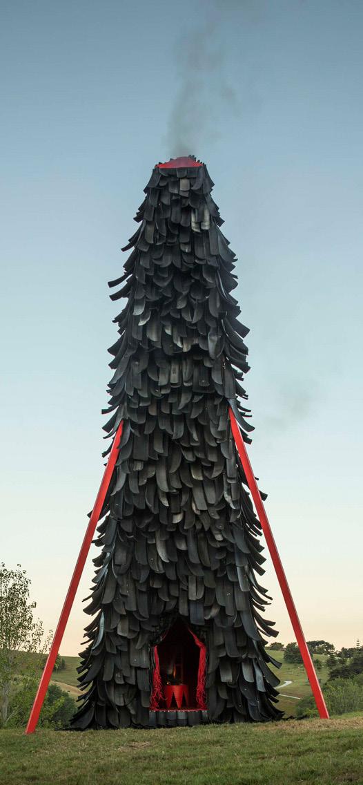
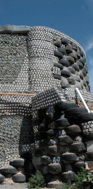
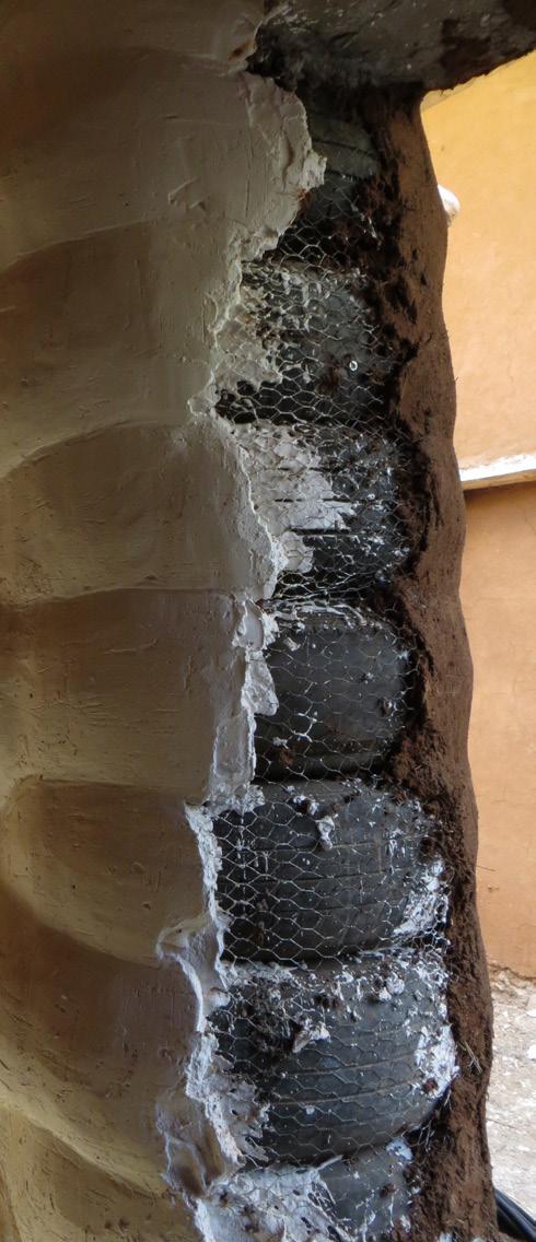
Natural rubber provides two of the core function sought within an architectural skin, waterproofing and insulation. Natural and synthetic rubber are renown for being proficient flexible insulators of heat and electricity, natural rubber having been used for these purpose since the 1800’s(4). Although natural rubber is not used in an insulation capacity within most buildings due to cheaper and function tailored alternatives, re-appropriated tyres (natural/ synthetic rubber blends) are commonly used as insulation in Eartship designs due to its economical and environmentally appropriate manner of achieving both thermal mass and structure in an actively thermal dynamic building (5,6).
Additionally its applications as a weatherproofed skin has been neglected due to its biodegradability. However if the rate of natural rubbers degradation can be controlled, and subsequently designed for the change induced by the removal of a materials mass or failure over time, spaces can be designed to be temporal and metamorphose the purpose of its space over time.
In order to determine the materials ‘habitability‘, the width required for a fully insulated wall can be calculated, by taking vulcanised natural rubbers thermal conductivity of 0.15 (W/mK) at 250C (7) and calculating the resulting U value.
R- VALUE = ( THICKNESS OF MATERIAL / (THERMAL CONDUCTIVITY OF MATERIAL)
U- VALUE = ( 1 / (R) (8)
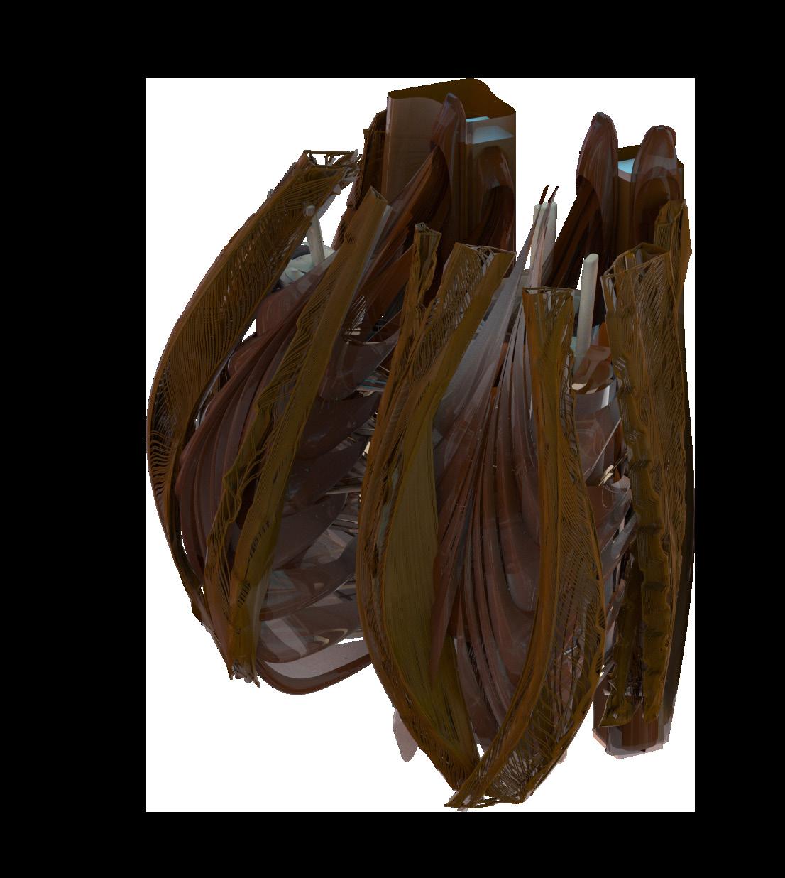
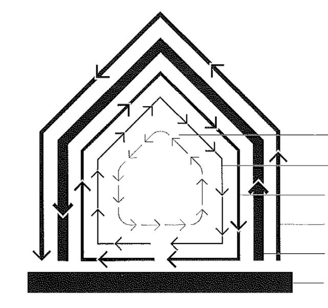
For a vulcanised natural rubber external wall to reach a U value appropriate to that of a domestic building in a temperate climate (0.18 W/m2 K)(9,10), a wall would have to be up to 800mm thick (excluding insulation from air cavities). Hence within the system proposed in this thesis and studio design project, the insulation requirements for a housing unit is spread across multiple individual layers that mediate the rate of degradation of the external skin (Figure 4).
1.0 ARCHITECTURAL CONTEXT
Figure 3: Earthship constructed with rubber tyres
Figure 2: Earthship wall section using tyres for thermal mass
Figure 4: Authors image. Spreading of walls
7 8
Figure 1: Belly of the Beast, shredded rubber tyre skin for temporary pavilion in new Zealand, by Declan Burn & Matt Ritani, 2015
CONTROLLED DEGRADATION
The rate of degradation of natural rubber can be controlled through manipulating the materials exposure to UV light as its sequence of degradation only begins once sufficient energy is provided to brake the material surfaces bonds (usually UV light) (2,3), following this the materials properties such as its tensile strength, significantly decrease through degradation by oxidisation(11,12).
By mediating a rubber layers exposure to UV light each layer in turn gradually fails (tearing or snapping of natural rubber fibre), exposing its neighbouring layer to UV light, in turn initiating its process of degradation.
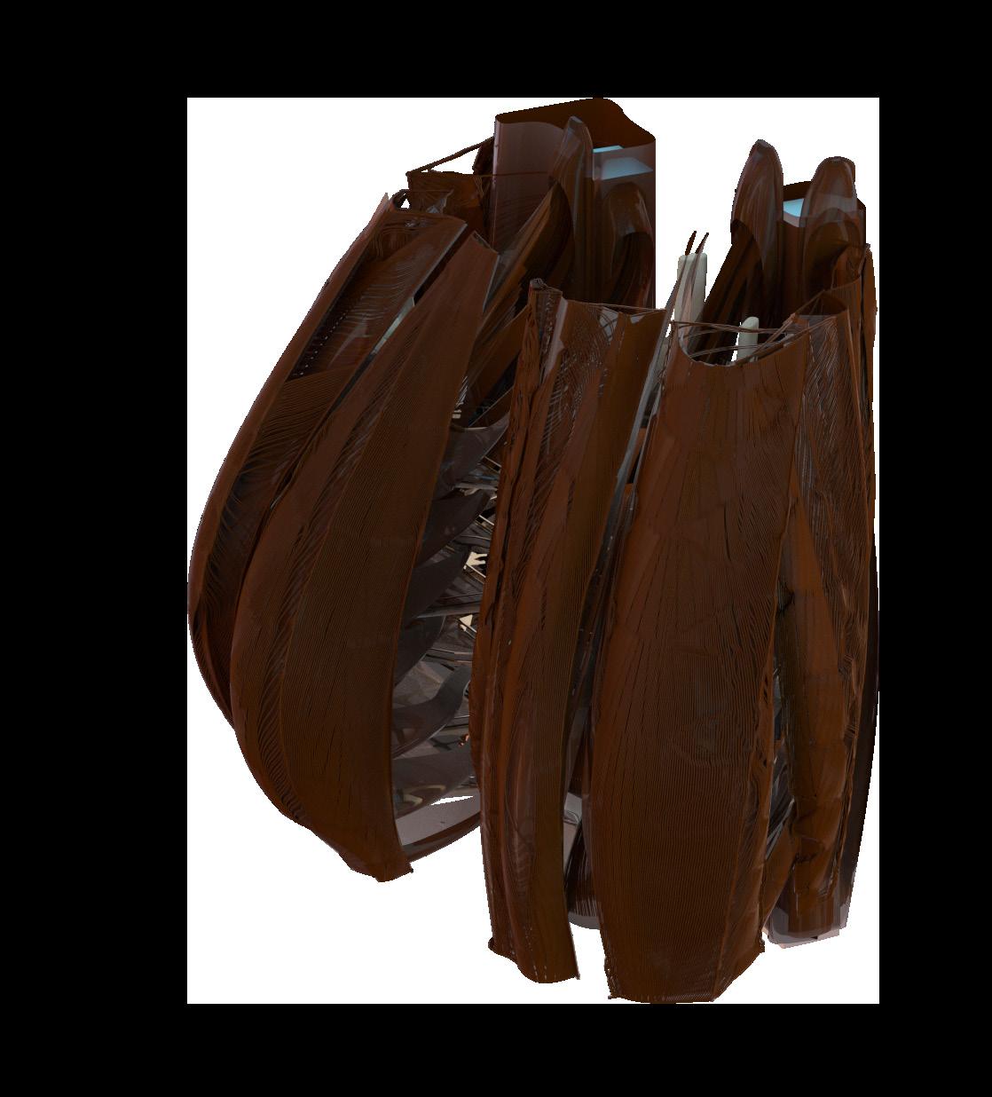
Multi layered degradation is in fact observable in every building in the last century, whereby the multi material build up of a traditional wall results in various rates of change of its components, “a building is always tearing itself apart”(13), as illustrated in Frank Duffy’s “shearing of layers” diagram in Figure 5. Steward Brand further explains this concept in his book How buildings learn, whereby he builds upon Frank Duffy’s well known statement:
“There isn’t such thing as a building. A building properly conceived is several layers of longevity of built components” (13)
The proposed system builds off this principal through situating the building within the context of the authors studio project in Japan, Tokyo. Where the average building life-cycle is 22.5 years(14), and the residing population is predicted to decline by one third in the next 80 years(15,16).
These two factors have informed an architectural strategy of a series of building skins that ‘shed‘ every 18 years ( based on analysis in chapter 2), reducing the inhabitable space in relation to a decrease in population, subsequently giving way for the space to become occupied by harvestable vegetation.
1.2
Initial state of the facade, un-aged
18 years weathering, outer layer begins to warp and fail, revealing the layer beneath
36 years weathering, second layer warps and fails, revealing the next layer beneath
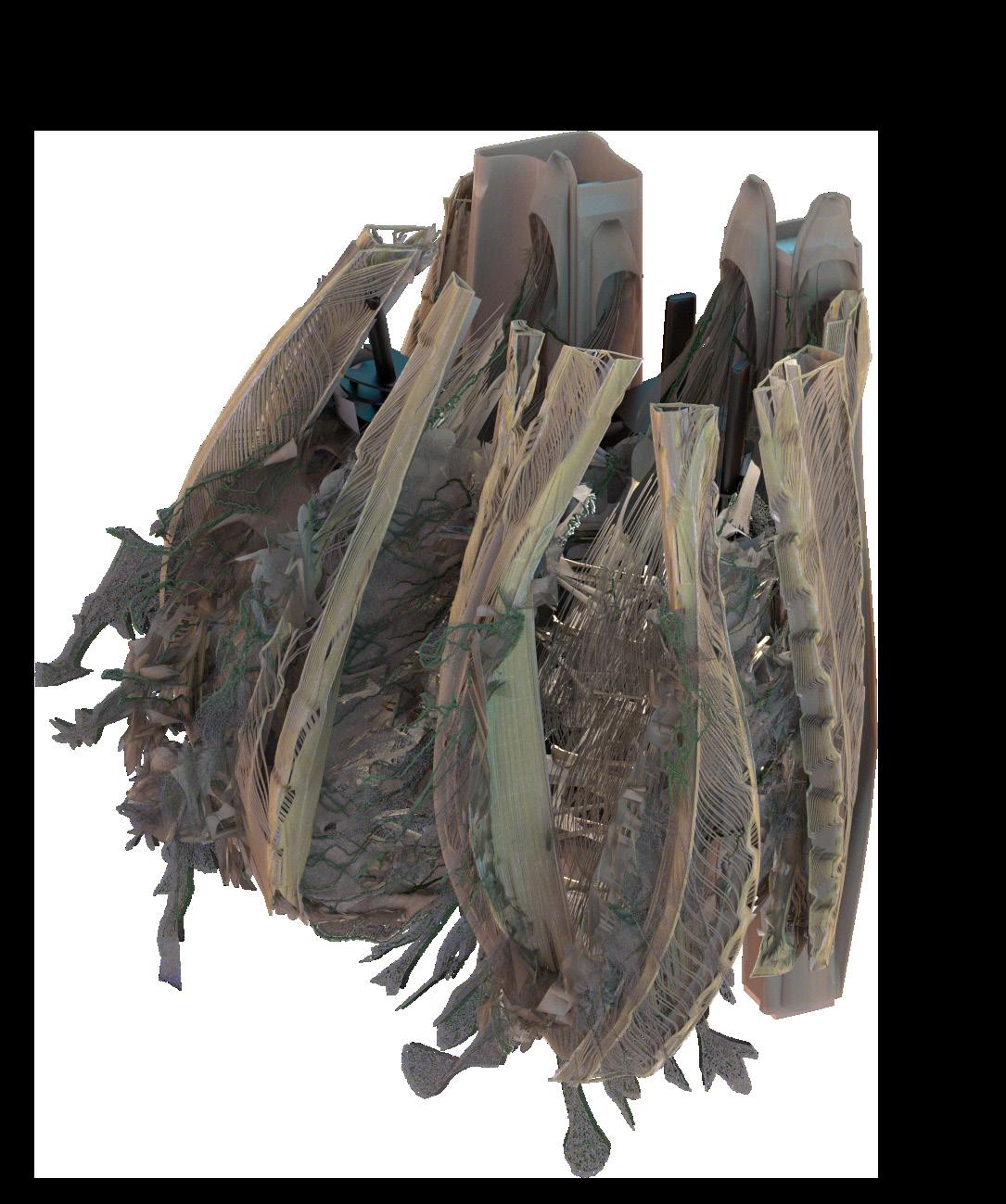
54 years weathering, the subsequent failed layers result in the outer space no longer being thermally insulative or protected from the elements, hence transitioning from the human occupation to that of a vegetal occupation.
Figure 6: Authors image. Fragment of authors design studio project, depicting gradual degradation of a multi skinned facade
STUFF SPACE PLAN SERVICES SKIN STRUCTURE SITE
Figure 5: Frank Duffy’s “shearing of layers diagram” Because of the different rates of change of its components, a building is always tearing itself apart. 1994 (13)
9
MANUFACTURING FOCUS
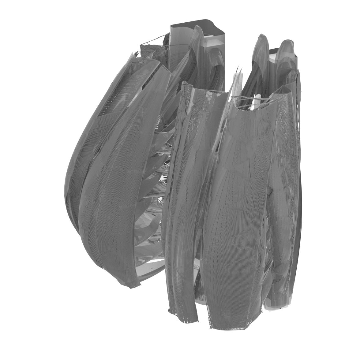
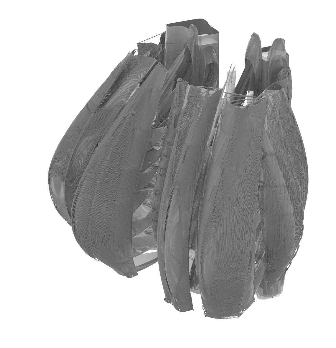
To enable the second time frame of operation of natural rubber, the material uses its elastic qualities to inflate through a pneumatic system, whereby the spacing of fibres along the skin dictate the amount of light which can pass through the semi opaque skin beneath, thereby altering the internal environment of the building.
The manufacturing methodology developed within this thesis will be tailored in developing a technique to construct the most outer skin within the proposed scheme (Figure7). Composed of a multitude of fibrous strands that are deformed via an internally placed balloon.
The strategies developed through the automated manufacturing of the proposed system within this thesis are envisioned to broadly apply and potentially influence future technicalities of constructing with natural rubber.
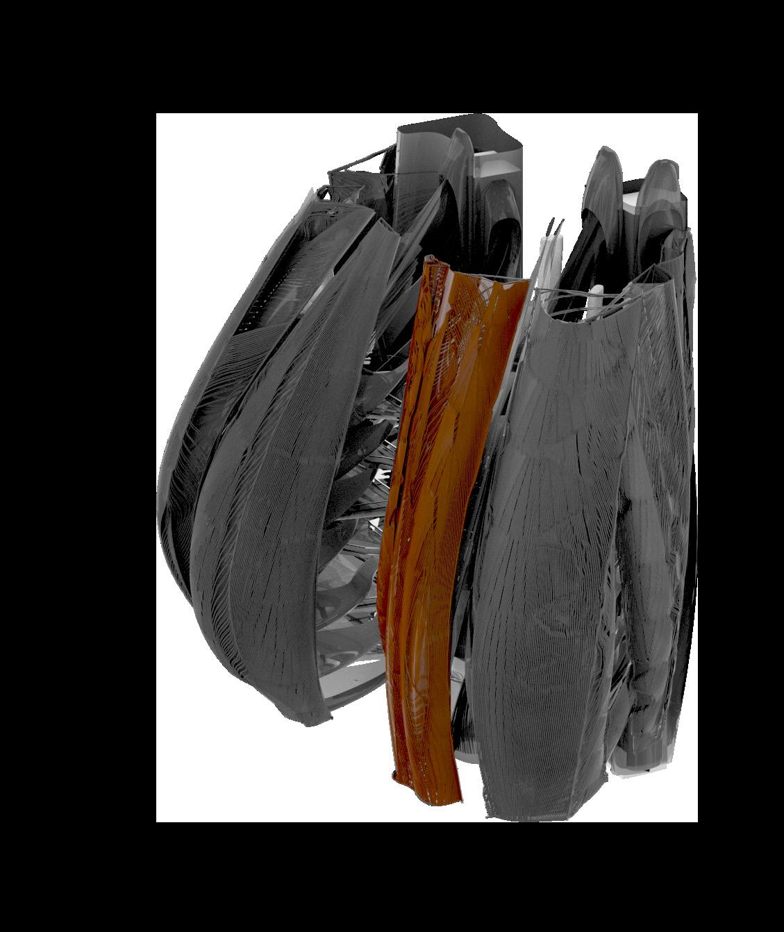 FOCUS OF MANUFACTURE
Figure 7: Authors image. Design studio project, focus of manufacture
1.3 11 12
Figure 6: Authors image. Design studio project, facade fragment Inflated with natural rubber balloon and wires
2.1
2.0 NATURAL RUBBER
ORIGINS & HARVESTING OF NATURAL RUBBER
Natural rubber is the oldest known polymeric material on earth and is profusely used commercially due to its high tensile strength and elasticity (17,18).
Unlike synthetic polymers, the raw material used in the fabrication of natural rubber is harvested from plants, such as the Hevea brasiliensis tree (19). Whereby through creating an incision along the outer bark, a milky colloidal suspension sap called latex, ‘bleeds’ from tree and is subsequently harvested(11,20).
Although over 2, 500 species of plants produce latex, (19,21) The most commonly harvested source is the Hevea brasiliensis due to its commercial viability in terms of production and the quality of latex harvested (19).
Following the first incision along the trees bark, it is left to ‘bleed‘ for up to four hours, after which the liquid sap is collected, strained of impurities and coagualted through the addition of formic or acetic acid (20). In this state its rubber constitution (known as Isoprene) is only around 30–40%, with the remaining percentage constituting mainly of water containing substances, proteins, carbohydrates, lipids and inorganic salts (21).
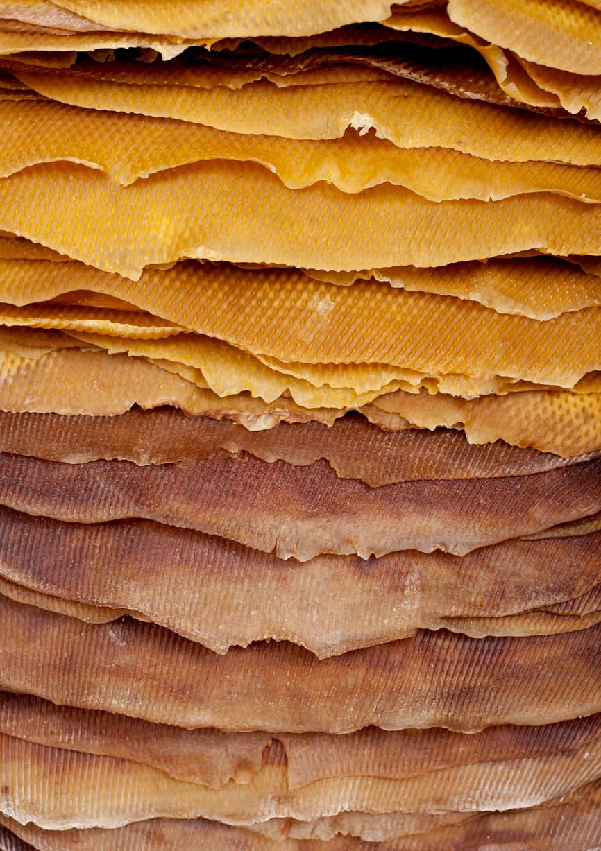
In order to extract non-desired constituents from the isoprene, the coagulated rubber is pressed between rollers to shape the rubber into 3–5 mm thick slabs , removing any excess water. It is then washed of the formic acid and either air dried (ADS) or smoke-dried(RSS) (20). The sheets produced from this process contain around 95% rubber constitution and are subsequently very elastic (21).
Alternatively, if desired to be kept in its liquid latex state, (which is common in the production of thin and highly elastic products such as medical gloves, condoms and balloons). Natural rubber can be exported as concentrated latex, which through a process of continuous centrifugation, the latex is condensed to a 60% rubber constitution (a lower percentage than air and smoke dried to maintain its liquid state) (21,22).
13
Figure 8: Walter A. Staked ribbed smoked sheets (RSS). 2011
2.2
PROCESSING & VULCANISATION
In its raw unprocessed state, natural rubber displays considerable physical instability, eventually rotting when exposed to UV light and oxygen, hence losing its elastic qualities. Additionally whence exposed to substantial heat it would become soft and sticky or whence exposed to cold temperatures becomes hard and brittle (17, 21 11).
This issue of natural rubbers physical instability is overcome through vulcanising the material. Vulcanisation is achieved through the application of intense heat (140-160oC at pressure (18,11)) to a natural rubber compound embedded with sulphur, activators and accelerators.
The combination of sulphur with natural rubber at hight temperature, creates cross-links within the materials long chains, subsequently increasing the materials tensile strength and resilience as well as the maintenance of these properties over a large temperature range (11,23). As the process of vulcanisation is irreversible and effectively ‘solidifies‘ the final form, this stage is performed last in the fabrication of rubber products.
Within the stage of processing and manufacturing rubber products, natural rubber can be either processed in its liquid state latex or with ‘dry‘ rubber such as ADS and RSS sheets.
Dry rubber is priorly embedded with additives for tailored properties through mastication of the rubber, it is then calendered, extruded or moulded before its vulcanisation (20, 24). Whereas in its liquid state latex, additives are directly mixed into the liquid, whereby a mould is then dipped into the latex mix, (which adheres and sticks to the form whence retracted). Its is then vulcanised in its moulded state(11, 25).
Unlike the gradual addition of additives in the mastication process used in dry rubber. In the case of a centrifuged latex concentrate, these agents are directly mixed into the liquid, where a mould is then dipped into the latex mix, the latex adhering to the form is then heated and vulcanised.(11)
Mastication consists of passing rubber through mechanical rollers to render it softer and hence more workable whilst additives are poured in between the rollers(11). Finally, the rubber is either Calendered, Extruded, or Moulded depending on the specification of the product prior to its vulcanisation.(11)This process is widely used in the production of tyres. (24)
TAPPING LATEX COLLECTED COAGULATED ROLLED DRIED AIR DRIED (ADS) QUALITY GRADED ADDITIVE MIX MASTICATED DIP COATED VULCANISED AMMONIA ADDED SMOKE DRIED (RSS) HEAT BLENDED COMPRESSION MOULDING CALENDERED WASHED Four to five hours Five to ten days Refer to appendix for quality grade system Additives added to liquid latex Masticated for malleability and addition of additives Moulds dipped in liquid latex compound Heated between 150-160OC at high pressure Ammonia added between 0.2 to 0.7 % to prevent coagulation Two to five days at 50 to 60 C Heated at high temperature and pressure to blend additives Washed of impurities from exterior Remove excess water content Formic acid mixed with latex Collected after four hours Tree is ‘tapped‘ for latex
INJECTION MOULDED
15
Figure 9: Authors image. Processing of natural rubber
2.3
ADDITIVES & BLENDS
In addition to the additives used in vulcanisation, during the processing of the rubber, additional additives are implemented into the mix to further tailor the rubber for particular properties and specifications. Vulcanised rubber mixed with additives is refereed to as a compound.
To prolong the materials longevity and resistance to weathering, anti-degradent additives such as UV absorbers are used to either absorb, reflect or refract damaging UV rays (26). Alternatively, antiozonants and antioxidants can be used to build up a protective film which mediates the rate of oxidisation, and subsequent degradation (11,26).
Fire retardation can also be implemented through a combined composition of organoclay, zinc hydroxystannate (ZHS) and chlorinated paraffin (CP) (27).
Unfortunately the implementation of most additives, reduces the elastic properties of the rubber as well as increases the complexity of its recycling and biodegradability(11). Natural rubbers biodegradability properties are further complicated when blended with synthetic rubbers such as Butadiene rubber (BR) and styrne butadiene rubber (SBR).
These general synthetic purpose rubbers which display similar qualities to that of natural rubber but with much higher impact strength, resistance to ozone cracking and resistance to degradation by oils, do not have the same elastic qualities as that of natural rubber(21,11,28). Hence synthetic/ natural rubber blends are created for tailored purposes such as tyres.
17 18
RUBBER BLENDS FILLERS PLASTICIZERS VULCANISING AGENTS REINFORCING FILLERS ACTIVATOR S ACCELERATORS SULPHUR DILUENTS UV ABSORBERS ANTI- OZONANTS ANTI- OXIDANTS ANTI DEGRADANTS ANTI FLAMABLES
ADDITIVES SYNTHETIC
NITRILE,
-Sulphur -MBT - zinc oxide -
- Carbon Black - Silica - Carbon Black - Titatium oxide - Zinc oxide - 6PPD - DPPD - ETMQ - 6PPD - DPPD - ETMQ - Range of oils & Paraffin - ZHS - CP - DBBO -Sb2 O3 - Clay - Calcium carbonate - GDPG - MBT - ZDRC
BUTADIENE RUBBER (BR) STYRNE BUTADIENE RUBBER (SBR)
POLCHLOROPENE, ETHYLENE PROPYLENE, POLYBUTADIEN...
stearic acid
Figure 10: Authors image. Common additives and synthetic blends
2.4
DEGRADATION
In its raw state natural rubber will degrade rapidly whence weathered. Subsequently UV absorbers, antioxidants and antiozonants are used to contribute in prolonging a vulcanised rubber compounds service life by preserving their elastic and resilient properties over a longer time frame.

The service life and durability of rubber is dependant on its exposure to oxygen, ozone, UV light and heat, which all contribute to its ageing process and subsequent degradation due to natural rubbers high unsaturation(29,25). The major cause of degradation is caused by the rubbers exposure to oxygen. However prior to the commencement of its degradation by oxidisation, energy is required to break the carbon-carbon or carbon-oxygen bonds in the polymer chain. This energy usually originates from prolonged exposure to UV but can also be caused by applied stress or extreme heat (2,3). Hence when natural rubber is protected from these degradation initiators, Its mechanical properties are preserved for significantly longer periods of time.
However through prolonging its lifespan through the inclusion of fillers (in particular carbon black), certain accelerators and synthetic rubbers, natural rubbers biodegradable properties are undermined (29). Hence, their inclusion must be minimised throughout its processing if biodegradtion of the material is required.
19
Figure 11: Hesse E. 30 year degradation of Latex work titled “Aught“ by Eva Hesse . 1968
2.5
INTERNAL ENVIRONMENT DEGRADATION
Authors review on data collected by Rapra technology Ltd on the Natural ageing of rubber: changes in physical properties over 40 years.

The rate of a rubbers degradation, is dependant on various factors such as the grade of natural rubber sourced, the vulcanization system and the type of antidegradant agents used. Due to the complexity of predictive ageing with the various blends of compound rubbers, a natural ageing programme was developed in 1958 with rubber and polymer testing company Rapra technology Ltd to determine the natural alteration in physical properties in rubber compounds over a 40 year period.(30)
The test consisted of placing 19 different test samples of varying blends of natural and synthetic rubber within internal environments in which the pieces were placed unstrained (with the exception of a long term compression set samples) with free access of air but excluding light to simulate shelf storage. (30)
Although the placing of the sample pieces internally (due to the erratic nature of external conditions over this time period) only provides relevant data for unlit conditions, sample rubber composites were placed in 3 different climates to account for the effect of climatic variance such as temperature and humidity. The three climates consisted of one temperate climate in Shawbury England(average indoor temperature range between 18-25oC). One hot and dry climate in Clonacurry Australia(average daily minimum, mean and maximum temperatures were 18oC, 25oC, 32oC). As well as one hot and wet climate in Innisfail Australia(average daily minimum, mean and maximum temperatures were 19.8oC, 23,6oC and 28.2oC)(30).
Sample composites were tested bi-annually for changes in mechanical properties. Of the 19 pieces sample blends tested, four of these were natural rubber composites, of which the first, compound A, contains the least amount of additives to natural rubber proportion therefore this composite was selected as the sample of my review.
Although multiple properties were tested for, such as tensile strength, hardness, modulus 100% and modulus 300%, the authors focus lies in the performance of the materials elongation at break as these results will most significantly affect the intended deformation of the architectural facade.
21 22
Figure 12: Rapra Technology Ltd. 40 year natural ageing data of natural rubber compound A. 2000
The results displayed that compound A’s elongation at break, in a temperate climate (TC) decreased by 48% after a 40 year period. In the hot and humid climate (HWC) decreased by 71 %, and in the hot and wet climate (HDC) 81%.
Overall the tests show that over time the materials elasticity decreases at a fairly constant rate, however it is evident that an increase in temperature drastically increases the rate of its deterioration. Although not mentioned in the report by Rapra technology Ltd, it might be assumed the increase in temperature, provided sufficient energy for the breaking of the bonds and subsequently dictates the rate and extent degradation by oxidisation occurs. As well as oxidisation, the natural occurrence of crystallisation in natural rubber, caused by changes in temperature would have increased the hardness of the material (and subsequent decrease of elasticity)(2,31,32,33).
These assumptions correlate with polymer conservationist notes, which state that chemical reactions are doubled with each 10oC increase(2,32). For optimal preservation conditions, it is suggested to store polymers away from UV emissions, with a maximum 100 lux, at 10oC and 50% humidity and preferably lower levels of oxygen. This is standard procedure for most conservation of polymer artwork or museum pieces (2,31,32,34).
Once the rubber composites were collected after the 40 year test, most of the samples were considered to still be in ‘usable’ condition (apart from the test pieces in stretched conditions) by Rapra technology Ltd (35). Due to the lack of UV emitted onto the pieces or any other weathering exposure, the performance of the material sample in these conditions can be compared to that of the materials performance in internal conditions of a building not exposed to natural lighting (UV) over a similar time frame.
Its worth of note, as to the artificial lighting of internal rooms, incandescent bulbs have little to no UV radiance (36), therefore due to its minimal effect degradation by artificial lighting is not accounted for.
Natural Ageing(Years) Temperate Climate Hot & Wet Climate Hot & Dry Climate Elongation at Break (%) 100 200 300 400 500 600 700 5 10 15 20 25 30 35 40
23 24
Figure 13: Redrawn from, Rapra Technology Ltd. Elongation at break of 40 year natural ageing data of natural rubber compound A. 2000
EXTERNAL ENVIRONMENT DEGRADATION
Authors review on data collected by Rapra technology Ltd on the Ageing of rubber: accelerated Weathering and Ozone test results & Ageing of rubber: accelerated heat ageing test results.

Forty two years after the natural ageing of rubber test began, Rapra technology Ltd conducted follow up experiments, whereby accelerated heat ageing and artificial weathering and ozone experiments of the same rubber compounds were tested for the same alteration in mechanical properties but over a different time frame(37, 38).
The pieces were tested over a period of 6 months in an artificial heated climate (air exchange oven for heat) that simulated 23oC temperature over 40 years. The accelerated weathering climate (UVA 340 lamps with a black panel temperature of 45 °C, cycle of 4 hours condensation and 4 hours dry) experiment was also run over a 6 month time frame to simulate an accelerated weathered 23oC environment (37,38).
Once the experiment concluded and the data collected, the results were then extrapolated to provide a future time based prediction using the Arrhenius equation which was simultaneously compared to the results against the natural ageing tests (37,38).
The age accelerated heated results show that to reach the same 47.9 % decrease in elongation at break in the temperate climate of the natural ageing test, it would take 17.5 years in the artificially simulated 23oC climate. This difference in time can be attributed to its exposure to a UV source, as well as well as discrepancy and inaccuracies of a simulated environment over such a short time frame.
However, in order to obtain a weathered prediction over a future time frame, this data is then intended to be compared against the accelerated weathering and ozone tests, as per Rapra technology Ltd reviews instructions in Ageing of rubber: accelerated Weathering and Ozone test results (37).
The results of the weather experiment provide the order of magnitude of the effects of weathering in comparison to those from heat ageing over a predicted time frame.
2.6
25 26
Figure 14: Rapra Technology Ltd. Accelerated heat ageing test results of compound A. 2001
If an acceleration factor due to the higher irradiance in the weathering apparatus compared to natural sunlight is assumed it is possible to estimate the effects of weathering at 23 °C under natural exposure to light (37).
Although it can only be estimated due to variations in solar radiation, the equation below can be used to give an estimate of the order of magnitude of change that might be expected from weathering. Acceleration factors were derived from quoted irradiance and annual solar radiation figures (37). The factors used for the artificial weathering tests were conducted under UVA 340 lamps for a London climate, quantified at 14.0 (This weathering factor can be altered depending on location) (29).
C is the net change due to weathering after 6 months.
The year factor period is equivalent to only a relatively modest extrapolation of the 6 month exposure graphs(37), because of the uncertainty in the acceleration factor, the figures can only be considered an approximation of the predicted result.
In the table the estimated time frame is calculated for 10 years in a UK climate. However the equation provided in the paper allows for the author to conduct the same test at 17.5 years (the time frame estimated for the artificially heated simulation) .


Weathering estimated factor is 15%
223% elongation at break after 17.5 years from heat ageing (Figure 14).
15% of 223 =33.5
223-33.5= 189.5
Subtract the equivalent weathering degradation factor from the elongation at break recorded at that time frame.
428% initial elongation at break(Figure 12).
428 to 223 shows a decrease of 48% of its elongation at break
428 to 189.5 shows a decrease of 55.7% of its elongation at break
55.7-48= 7.7
7.7% difference in elongation at break
The calculated difference between the natural ageing test and the estimated predicted weathering test shows an 7.7 % difference in the effect on elongation before break whence exposed to UV after 17.5 years. Although the UV degradation should have lead to a higher number than 7.7% , which can be attributed to the inaccuracy of the prediction method. The result is extremely close to the to the percentage at the 10 year UK where a prediction 8% is recorded.
This might suggest the actual UV degradation is almost negligible over the 7.5 years (10 to 17.5 year calculation).
C 6 15 % % Change due to 17.5 years in UK 7.7 x x x x = Years 17.5 1 1 0.5 0.5 Acceleration factor 14 Authors calculation 27 28
Figure 15: Rapra Technology Ltd. Accelerated weathering ageing test results of compound A. 2001
This discrepancy can be partially explained when looking at the elongation at break graphs over the 6 month period heat ageing tests. Within all the rubbers, the elongation at brake graphs show a sudden dip in the first 30 days which accounts for about 10% of decrease in elongation at break (similar to the 8% and 7.7% in this case).


The dip is then followed by a seemingly constant rate of degradation. It is therefore assumed that based on the data collected, the energy provided by the UV exposure in the first month initiates the ‘braking of the bonds’ that allow oxidisation to commence and subsequently dictates the following rate of degradation once exposed (2,32). Therefore suggesting that UV degradation factor is only relevant in the first month which would explain the unchanging factor of 8% and 7.7% over a 7.5 year lifespan.
This analysis review of the experiments conducted by Rapra technology Ltd therefore concludes that UV exposure significantly effects the rate of degradation in the first month through the braking of the bonds (which can be similarly achieved with high temperature or stress), however based on the natural ageing test in figure 13, it is evident temperature determines the rate of degradation by oxidisation. This result supports observations made by polymer conservationists in museums (2,32,33,34). Additionally, it must be considered, that the equation, irradiance factors and other variable assumed factors only allow for an estimation at best, therefore the listed predictive numbers below are merely an approximation used to predict degradation as well as understated the principals and factors that drive its degradation (37).
The predicted behaviour of composite A with an estimated elongation at break of 190% after an averaged 18 years is therefore taken as the estimated lifespan for a single natural rubber layer of approximately 4mm tick (thickness of samples in the conducted test) and is hence used to determine the lifespan of the building at an estimated 54 life year cycle, with 3 cycles of shedding of layers.
29 30
Figure 16: Rapra Technology Ltd. 6 month weathering elongation at break results of compound A-H. 2001
NATURAL RUBBER COMPOSITE SELECTION
In order to determine the degradation behaviour for commercially available natural rubber compounds, three samples of varying blends were selected to cross reference their resistance to UV light and their individual elastic behaviour (relevant for the robotic manufacturing process)in relation to the results gathered from compound A Rapra technology Ltd accelerated ageing test.
The samples chosen were based on aspects such as, individual physical properties, commercial availability and application.
Linatex R was chosen based on its similar tensile strength to that of compound A, for long term comparison purposes as well the materials exceptionally high natural rubber content (95%) (39), making it an extremely high quality natural rubber with high elasticity, strength and resilience.

Para (shotblast/gum) rubber was chosen due to it also containing similar physical characteristics similar to that of compound A, however less expensive and more commercial available than Linatex R rubber
A natural/ synthetic rubber blend (NR/SBR Blend 70° Shore Rubber Sheeting) was selected as sample to be tested due to it being one of the most commercially used applications of natural rubber as well as being one of the cheapest, and low performing natural rubber blends.
2.7 PARA (SHOTBLAST/GUM) RUBBER PHYSICAL PROPERTIES: TENSILE STRENGTH 16 MPa 600 % 30 % Excellent 45o Sh.A -40 - +85oCTan 25 MPa 830 % 30% Excellent 38o Sh.A -40 - +70oC 0.96 g/cm3 Red 3 MPa 250 %Low 16 MPa -30 - +70oC 1.5 g/cm3 Black ABRASION RESISTANCE SPECIFIC GRAVITY ELONGATION AT BREAK HARDNESS RANGE COMPRESSION SET 22 HOURS @ 70OC TEMPERATURE RANGE COLOUR NR/ SR BLEND 70O LINATEX R
Figure 17: Authors image. Data sheet comparison of Para, Linatex and NR/ SR composite
31
Figure 18: Authors image. Photograph of Para, Linatex and NR/ SR composite sample materials.
The Young’s Modulus equation listed below is used to determine the stiffness of each sample material through determining the stress and strain from the data collected.
The results showed an expected linear behaviour as the jig and weight weren’t sufficient to reach the materials plastic stage (permanent deformation). As expected the LinatexR rubber which has the highest tensile strength displays the highest capability of withstanding load whilst the natural/ synthetic blend showed the least.
Therefore LinatexR would be the chosen composite blend in terms of commercially availability and application of high stress at a large scale application.
Force (N) (kg x 9.8ms-2) STRESS Nm-2 (Force/area) STRESS Nm-2 (Force/area) STRESS Nm-2 (Force/area) LINATEX LINATEX PARA NR/SR YOUNG’S MODULUS = STRESS 2 100 000 2 700 000 700 000 Force/ Area = STRAIN 4.2 4.2 4.9 5 x 10⁵ Nm -2 6.43x 10⁵ Nm -2 1.43x 10⁶ Nm -2 = = = Change in length/ initial length PARA NR / SR 15.827 318 916.666 1 978 375.000 7.987 665 583.333 998 375.000 887 444.444 23.667 972 250.000 2 958 375.000 4.067 338 916.666 508 375.000 451 888.000 19.747 645 583.333 2 468 375.000 11.907 992 250.000 488 375.000 17.787 1 482 250.000 2 223 375.000 9.947 828 916.666 1 243 375.000 214 111.1111 25.627 2 135 583.333 3 203 375.000 6.027 502 250.000 753 375.000 669 666.000 21.707 1 808 916.666 2 713 375.000 13.867 1 155 583. 333 1 733 375.000 16.807 400 583.333 2 100 875.000 8.967 747 250.000 1 120 875.000 996 333.333 24.647 2 053 916.666 3 080 875.000 5.047 420 583.333 630 875.000 560 777.777 20.727 727 250.000 2 590 875.000 12.887 1 073 916.666 1 610 875.000 18.767 563 916. 000 2 345 875.000 10.927 910 583.333 365 875.000 323 000.000 Failure 26.607 2 217250.000 3 325 875.000 7.007 583, 391.666 875 875.000 778 555.555 22.687 890 583.333 2 835 875.000 14.847 1 237 25.000 855 875.000
STRAIN (change in length/ Initial length) Change in length Change in length Change in length Stretched length Stretched length Stretched length STRAIN (change in length/ Initial length) STRAIN (change in length/ Initial length) LINATEX LINATEX PARA PARA NR / SR NR / SR 3.000 0.286 0.225 3.810 1.066 0.041 0.138 0.080 1.840 0.546 4.800 0.400 0.360 5.333 0.466 0.020 0.050 0.035 0.666 0.266 3.933 0.345 0.295 4.600 2.173 0.212 0.163 2.826 3.400 0.315 0.255 4.200 1.600 0.054 0.172 0.120 2.293 0.720 5.000 0.435 0.375 5.800 0.706 0.029 0.090 0.053 1.200 0.386 4.400 0.379 0.330 5.053 2.546 0.250 0.191 3.333 3.2533 0.304 0.244 4.053 1.266 0.046 0.155 0.095 2.066 0.613 4.933 0.416 0.370 5.546 0.586 0.025 0.075 0.044 1.000 0.333 4.133 0.365 0.310 4.866 2.386 0.231 0.179 3.080 3.640 0.326 0.273 4.346 1.866 0.195 0.140 2.600 Failure 5.1333 0.445 0.385 5.933 0.866 0.036 0.120 0.065 1.600 0.480 4.600 0.388 0.345 5.173 2.840 0.263 0.213 3.506 0. 300 0. 155 0. 435 0. 110 0. 370 0. 238 0. 330 0. 195 0. 450 0. 128 0. 405 0. 266 0. 319 0. 170 0. 445 0. 119 0. 385 0. 254 0. 348 0. 215 0. 460 0. 140 0. 420 0. 288 0. 361 0. 213 0. 475 0. 125 0. 420 0. 287 0. 390 0. 247 0. 510 0. 165 0. 454 0. 325 0. 379 0. 230 0. 491 0. 150 0. 440 0. 306 0. 401 0. 270 0. 520 0. 195 0. 463 0. 338 0. 116 0. 095 0. 129 0. 104 0. 121 0. 100 Failure 0. 111 Strain Strain Strain Stress x10 5 Stress x10 5 Stress x10 5 5 5 5 10 10 10 15 15 15 20 20 20 25 25 25 30 30 30 35 35 35 3 3 3 2 2 2 4 4 4 5 5 5 6 6 6 7 7 7 34 35
Figure 21: Authors image. Young’s modulus experiment, Para, Linatex and NR/ SR composite
Figure 22: Authors image. Young’s modulus experiment, Para, Linatex and NR/ SR composite
The results from the experiment showed that the Para and Linatex rubber stretched samples did not fail, in figure 27 a comparison can be seen between the stretched and non-stretched sample, the stretched Para rubber was permanently deformed, no longer displaying elastic behaviour but a plastic behaviour, whilst the Linatex rubber retained its elastic behaviour. The NR/ SR stretched samples failed after one hour into the experiment, due to its low tensile strength as opposed to the effect of UV degradation
After the one month test period, the Young’s modulus test was repeated on the un-stretched UV aged samples. The Linatex and NR/SR samples showed similar tendencies to their prior un-aged performance, however both showed a slight increase in stiffness. The Para rubber sample failed almost immediately, as seen in figure 27, this sample produced a hard outer surface displaying cracks, affecting the integrity of the material.
From this analysis, it can be determined that a high percentage natural rubber composite such as LinatexR rubber would be most suited to a long term performance over the time frame of a building skin due to a noticeable alteration of its properties consistent with that of the long term Rapra predictive experiment conducted. The Para rubber’s susceptibility to UV was too drastic to be considered and the NR/SR blend performed poorly overall.
LINATEX PARA NR/SR 2 200 000 1 000 000 5 1.5 4.4 x 10⁴ Nm -2 Neglectable 6.67x 10⁵ Nm -2 = = Strain Strain Strain Stress x10 5 Stress x10 5 Stress x10 5 5 5 5 10 10 10 15 15 15 20 20 20 25 25 25 30 30 30 35 35 35 3 3 3 2 2 2 4 4 4 5 5 5 6 6 6 7 7 7 1615 g 815 g 2415 g 415 g 2015 g 1215 g Initial length Length with bucket (315g) 1815 g 1015 g 2615 g 615 g 2215 g 1415 g 1715 g 915 g 2515 g 515 g 2115 g 1315 g 1915 g 1115 g 2715 g 715 g 2315 g 1515 g 75 LINATEX mm Elongation PARA mm Elongation NR / SR mm Elongation 255 0.255 0.18 145 0.145 0.07 0.007 330 0.330 0.255 98 0.098 0.023 0.002 0.045 292 0.292 0.217 208 0.208 0.133 93 273 0.273 0.198 175 0.175 0.1 352 0.352 0.277 120 0.120 0.045 0.004 310 0.310 0.235 230 0.230 0.155 265 0.265 0.19 168 0.168 0.093 0.01 340 0.340 0.265 105 0.105 0.03 0.003 301 0.301 0.226 215 0.215 0.14 285 0.285 0.21 195 0.195 0.12 365 0.365 0.290 132 0.132 0.057 0.005 321 0.321 0.246 242 0.242 0.167 75 120 0.120 107 Failure 75 82 0.082 77 0.077 75 Failure 79 0.079 85 0.085 78 0.078 80 0.080 Force (N) (kg x 9.8ms-2) STRESS Nm-2 (Force/area) STRESS Nm-2 (Force/area) STRESS Nm-2 (Force/area) 15.827 318 916.666 7.987 665 583.333 887 444.444 23.667 972 250.000 4.067 338 916.666 508 375.000 451 888.000 19.747 645 583.333 11.907 992 250.000 17.787 1 482 250.000 9.947 828 916.666 214 111.1111 25.627 2 135 583.333 6.027 502 250.000 669 666.000 21.707 1 808 916.666 13.867 1 155 583. 333 16.807 400 583.333 8.967 747 250.000 996 333.333 24.647 2 053 916.666 5.047 420 583.333 560 777.777 20.727 727 250.000 12.887 1 073 916.666 18.767 563 916. 000 10.927 910 583.333 Failure Failure 26.607 2 217250.000 7.007 583, 391.666 778 555.555 22.687 890 583.333 14.847 1 237 25.000 STRAIN (change in length/ Initial length) Change in length Change in length Change in length Stretched length Stretched length Stretched length STRAIN (change in length/ Initial length) STRAIN (change in length/ Initial length) 2.4 0.093 0.93 3.4 0.026 0.6 0.306 2.9 1.77 2.64 1.33 3.69 0.053 0.6 3.13 2.06 2.53 0.133 1.24 0.35 0.04 0.4 3.01 1.86 2.8 1.6 3.86 0.067 0.76 3.28 2.22
38 39
Figure 26: Authors image. Young’s modulus experiment, Para, Linatex and NR/ SR composite
Figure 27: Authors image. Young’s modulus experiment, Para, Linatex and NR/ SR composite
3.0 FLEXIBLE FABRICATION
FLEXIBLE FILIGREE
Following an analysis of the materials performance and predicted rate of degradation, the manner of manufacturing is considered in tandem with the flexible and deformable qualities of the material.
Hence an automated filament distribution method is selected as it enables multiple axis of flexibility and allows a full degree of elastic freedom, allowing the properties of the material to be exploited throughout the manufacturing process.
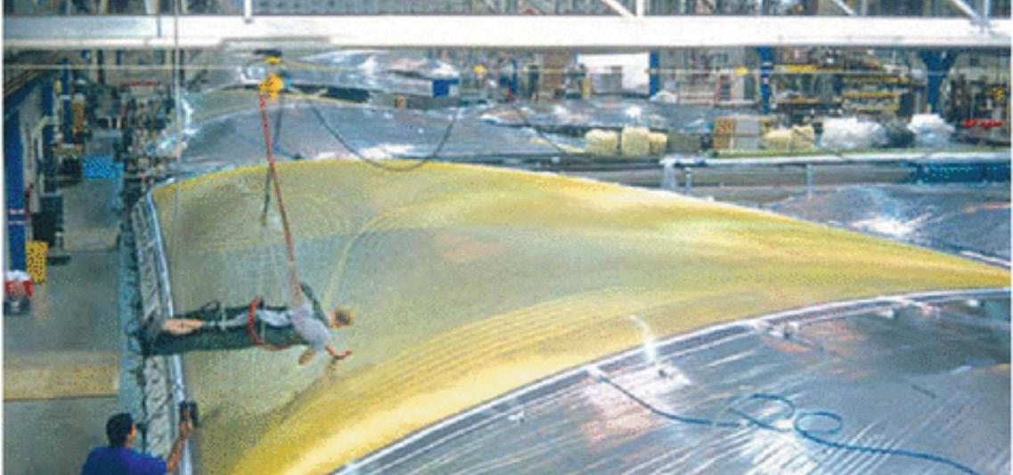
The application of fibres in creating complex curvatures that require a degree of freedom in their construction process can be observed in the manufacturing of 3DL (3 Dimensional Laminate) sails. Whereby through laminating high performance fibres, 3D aerodynamically shaped surface are created in accordance with tailored ‘load paths’(40). The scale of the production of sails would be similar to the scale required of the production of the proposed architectural facade.
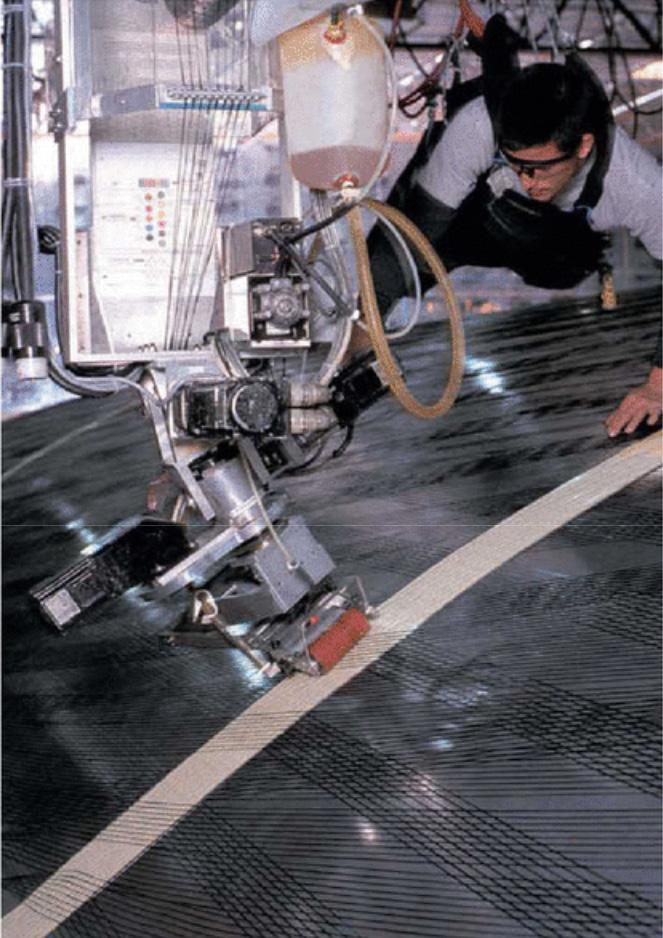
In order to manufacture complex large span curvatures formed of multiple strands as in the case of modern sails, robotics play a significant role in the coordination of multiple individual fibres in a complex multi axis environment, hence forms the focus of the developed designed manufacturing strategy.
3.1
Figure 33: North sails. Sail fabrication, fibre placement head following load path trajectories along large span double curved surface. 1998
42
Figure 32: North Sails. Sail fabrication on inflated mould.1997
ENABLING SIX AXIS ROTATION
Previously reviewed robotic weaving techniques use a ‘stationary’ rotational jig, constrained to a single axis of rotation, this system is known as a tool to piece system. However the constrained jig limits the use of the 6 axis degree of freedom of the robotic arm.
Therefore a Piece to tool system is opted for in this research project, whereby the filament dispenser is placed in a static position, and the rotational jig is attached to the robotic arm as the end effector. The proposed system is similar to that of the 2013-2014 ICD/ITKE research pavilion (43), where two robotic arms coordinate the placing of the jig in accordance to the position of the static filament dispenser.
A piece to tool system allows the jig to take on a range of angles, which for this project can then be programmed to be positioned in accordance with the location of the opened rib slits.
However in order to synchronise the 360o continuous rotation of the end effector, the positioning of the robotic arm must work in tangent with the driver of this rotation, which in this case is a stepper motor driven by an Arduino UNO board. To allow a dialogue between the rotational Arduino code and the robotic positioning, a Universal robot (UR 10) was selected due to its compatibility with an Arduino set up.
A6 A5 A4 A3 A2 A1
360 continuous rotation 360 continuous rotation 360o continuous rotation Figure 41:Authors image. 360o continuous
jig
rotational
placed onto robotic arm
3.3 48 49
Figure 42: Authors image. Universal robot, UR 10, six axis of rotation joined to continuous
360
o continuous rotation of the end effector
360O CONTINUOUS ROTATION END EFFECTOR
In order to enable a continuous 360o rotation of the jig to be wound upon, a Nema 17 Bipolar 0.9deg 46Ncm was chosen as the means by which to rotate the end effector. The set up consists of wiring up the stepper motor to a stepper driver which is then wired to an Arduino Uno board and an 24V 15 Amp power supply.
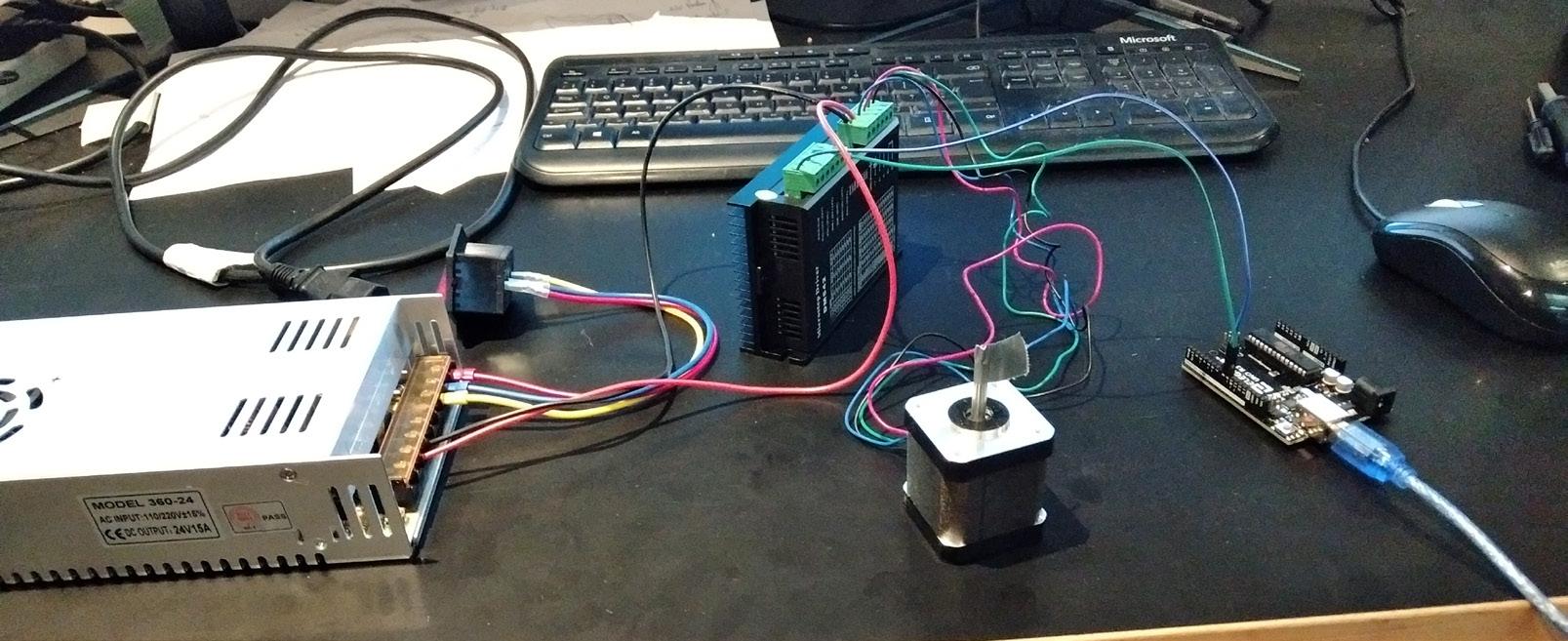
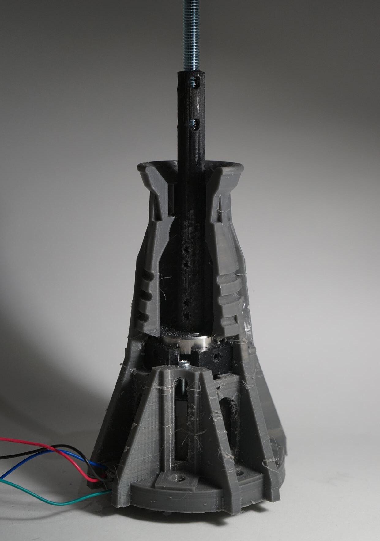
The stepper motor is then placed inside the end effector designed for this project which is subsequently attached to the flange of the robotic arm. The drive shaft of the stepper motor is then connected to a threaded rod placed inside of copper tubing, which in turn drives the entire rotation of the end effector.
Depending on the angle of the end effector in relation to an x, y, z coordinate system, the vertical load on the stepper motor shaft varies, hence the rotational speed slows down proportionally. Therefore the estimated variance in rotational speed is dependant on the end effectors position.
On Input AC L Input AC N Ground Output VPower supply 24 v, 15a Arduino Uno ST-M5045 Stepper motor Driver Stepper motor 360 continuous rotation Stepper motor Steel Threaded Copper Pipe Ball bearings M5 Gauges 3D print PETG 3D print PETG Flange M6 30mm M3 20mm END EFFECTOR PUL + PUL - DIR+ DIR- ENA+ ENAGND VCC A+ A- B + B DC Power USB Port 9 8 Output VOutput V+ Output VOutput V+ Output V+ Off
Figure 43: Authors image. Stepper motor connected to Arduino & stepper motor driver
Figure 44: Authors image. Wiring set up
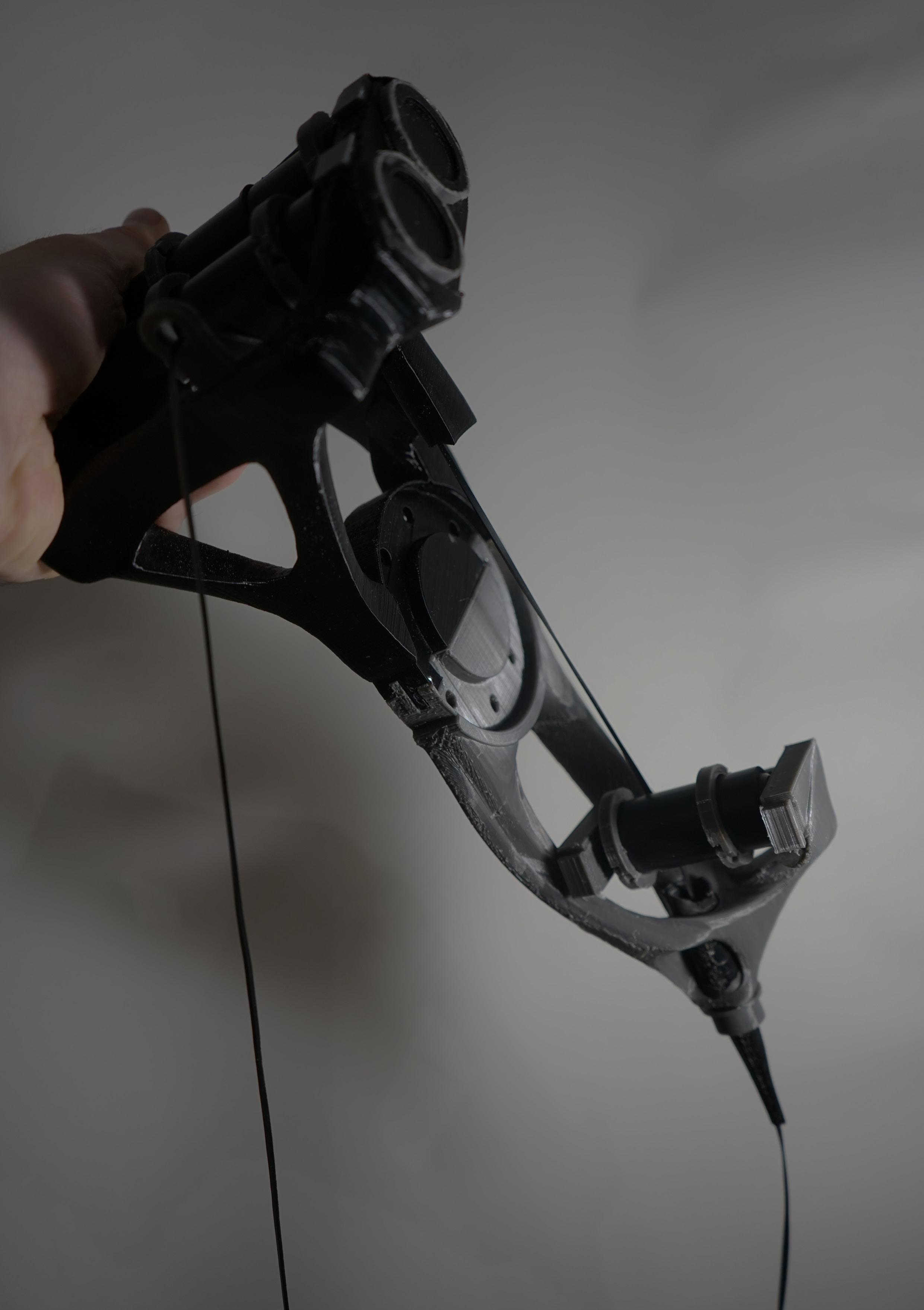
Figure 45: Authors image. End effector design Figure 46: Authors image. End effector prototype (next page)
3.4 50 51
Figure 47: Authors image. End effector prototype (next page)
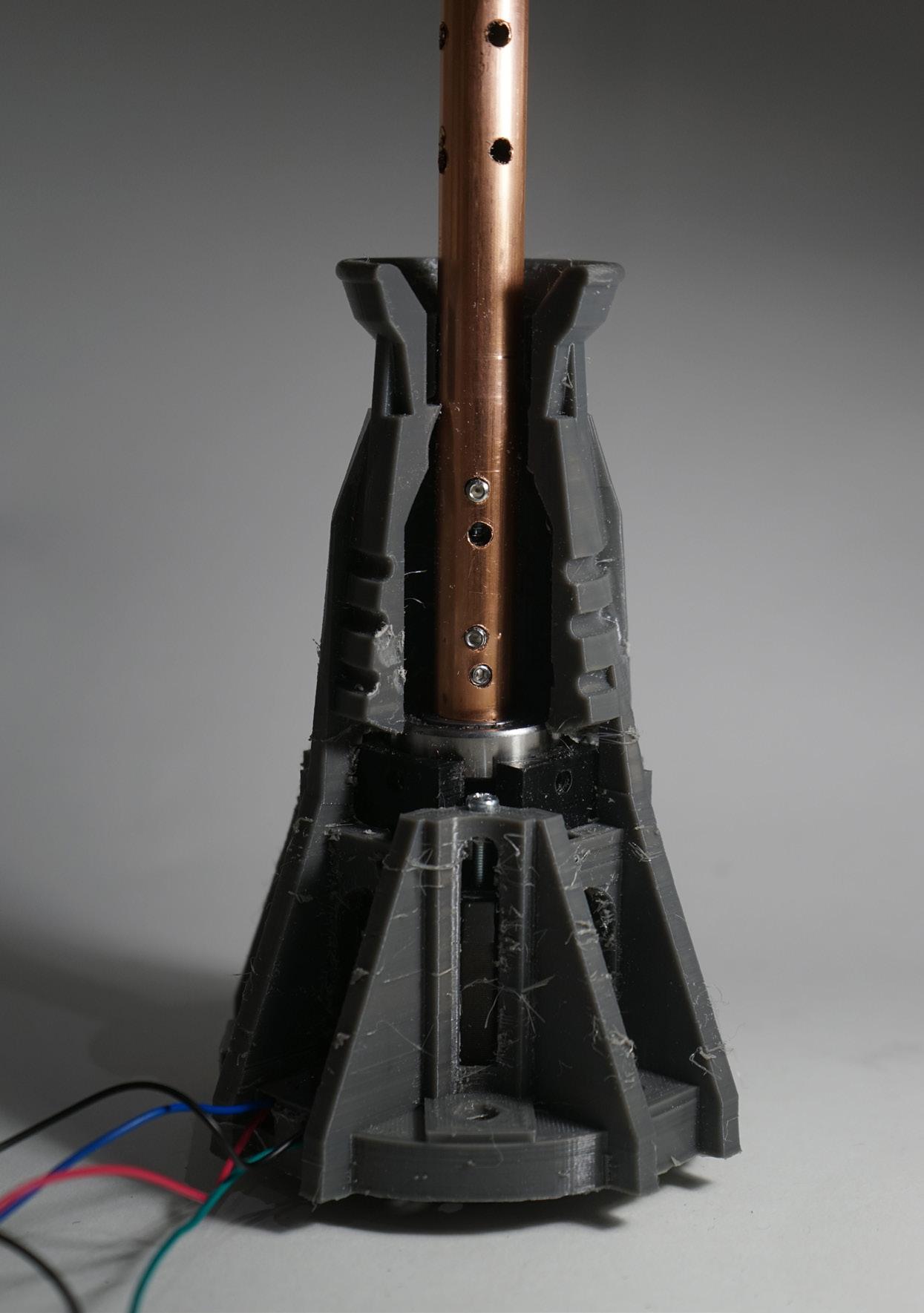
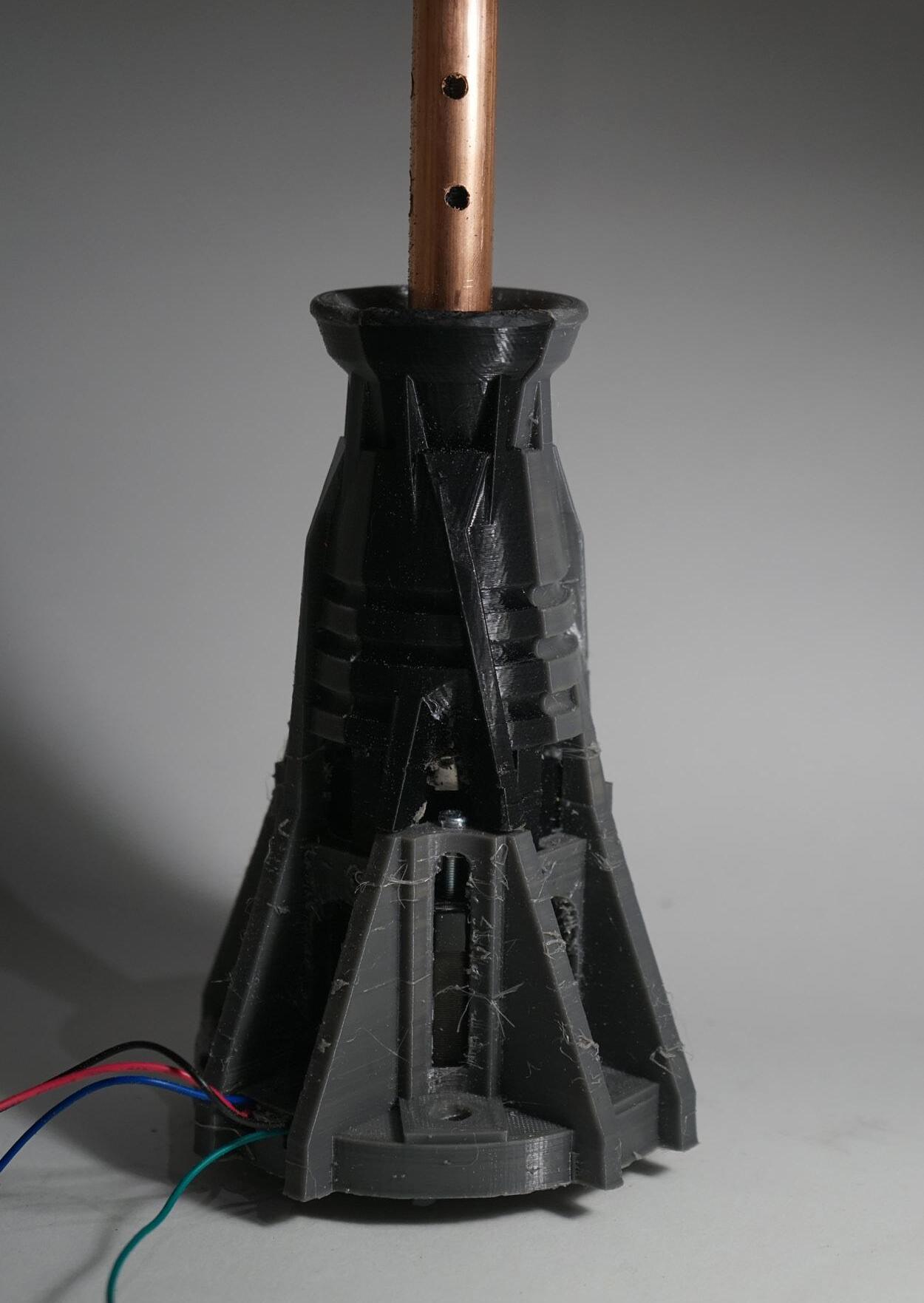
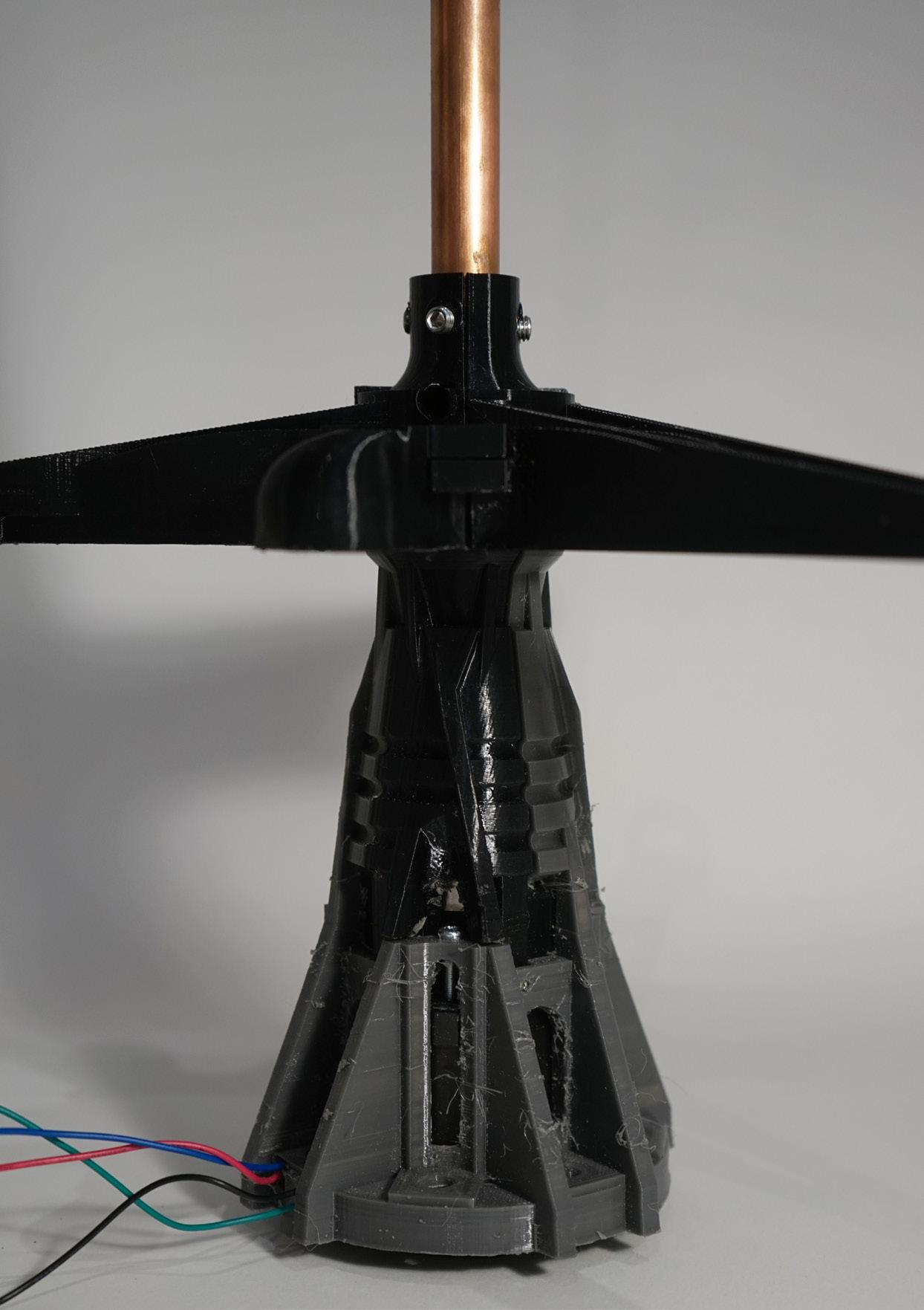
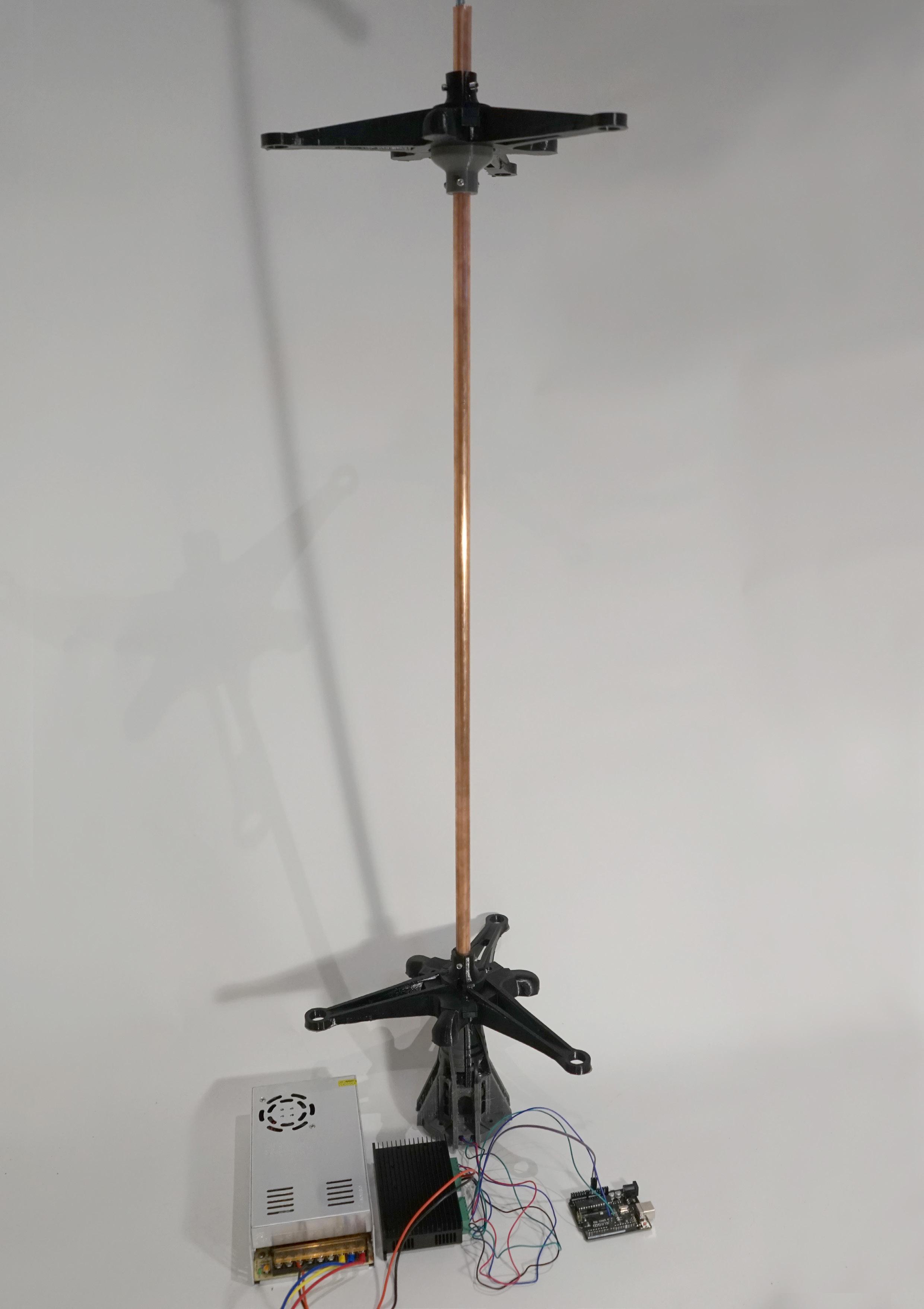
FILAMENT DISPENSER
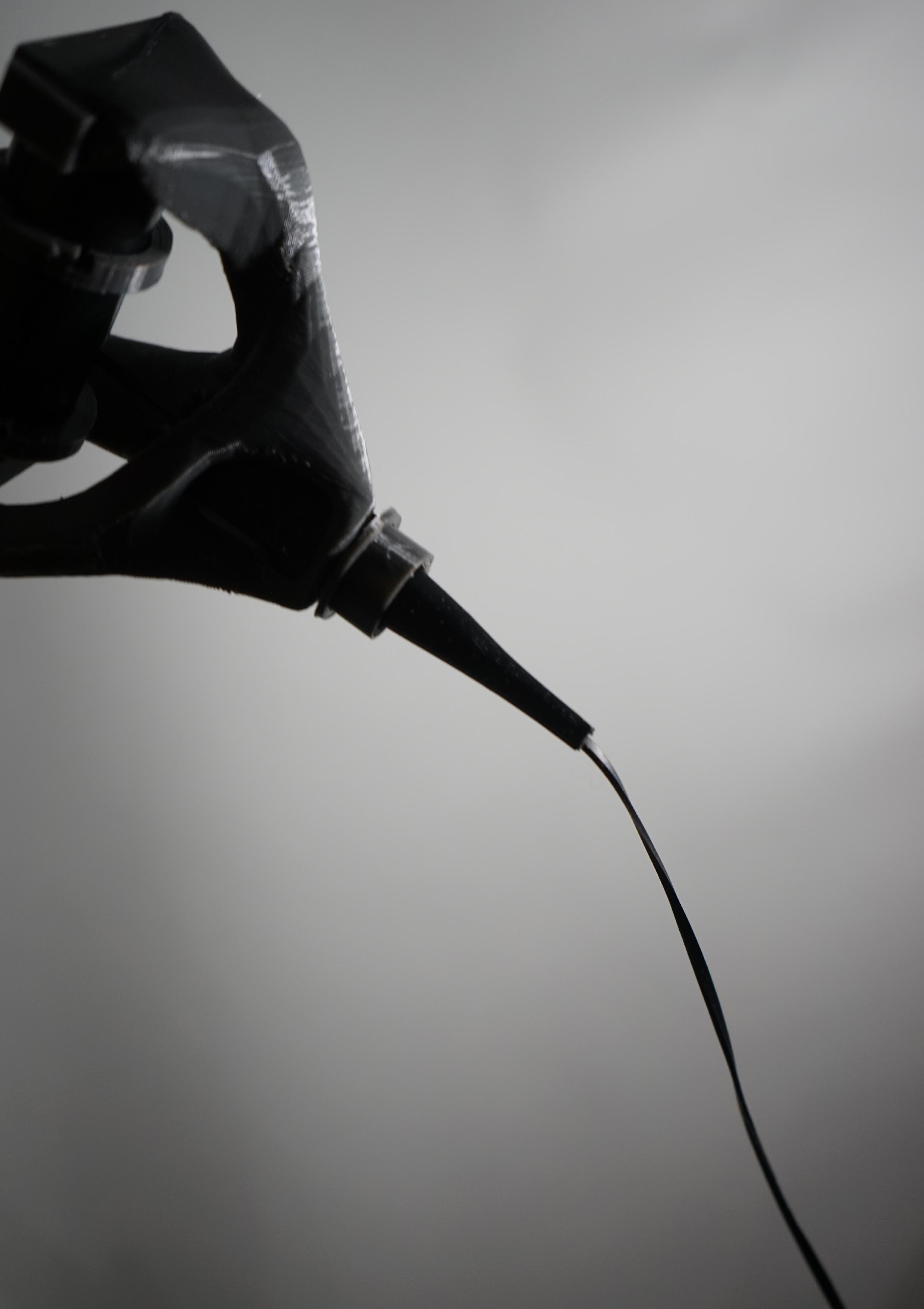
Whence dispensing filament, a continuous tension of the strand must be maintained throughout the distributive cycle to prevent slack which can cause an uneven rate of distribution. Tension is created through introducing 3 rollers which mediate the amount of tension in the natural rubber fibre through creating 3 rotational axis with which the fibre is constantly in contact with.
The tension created however is substantially different to the filament dispensers used in the Elytra pavilion by ICD Stuggart due to the elastic nature of the rubber, therefore the tension was diminished by reducing the axis of friction to 3 points.
Figure 48: Authors image. 3 axis of tension
Figure 49: Authors image. Filament dispenser annotation
Figure 50: Authors image. Filament dispenser prototype (next page)
Figure 52: Authors image. Filament dispenser prototype (next page)
Figure 51: Authors image. Filament dispenser prototype (next page)
Synthetic
3D print PETG Trackers Synthetic
M6 30mm Rubber filament Feeder 3.5 54 55
Figure 53: Authors image. Filament dispenser prototype (next page)
rubber coated rollers
rubber coated rollers
COORDINATION OF TOOLS
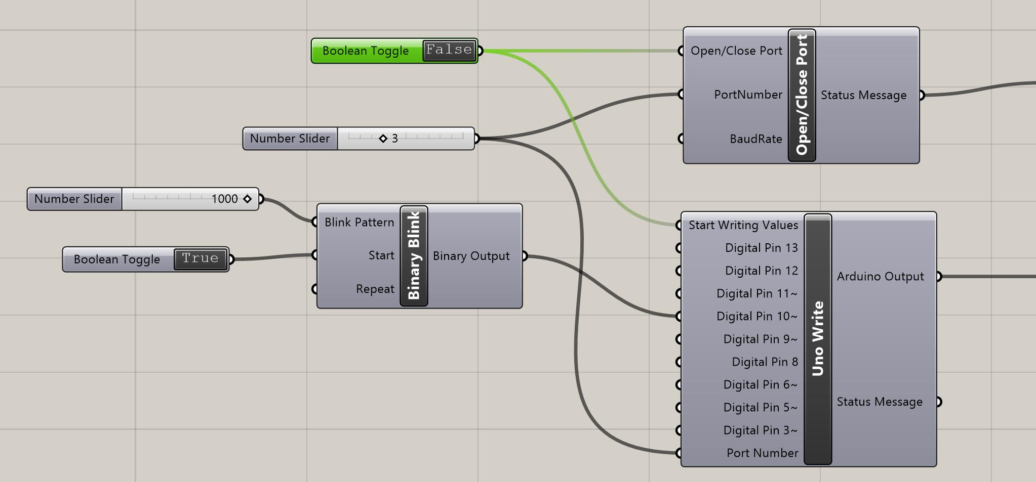
In order to coordinate the developed tools into a single synchronised path, the logic developed within the Arduino code driving the continual rotation of the stepper motor was implemented within Grasshoper using the open source plugin ‘Firefly‘.
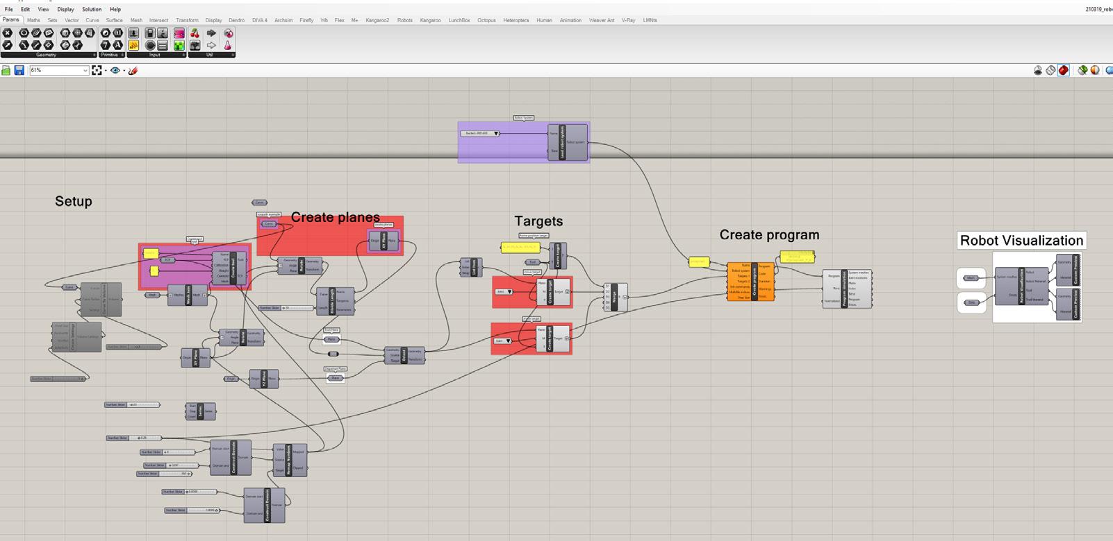
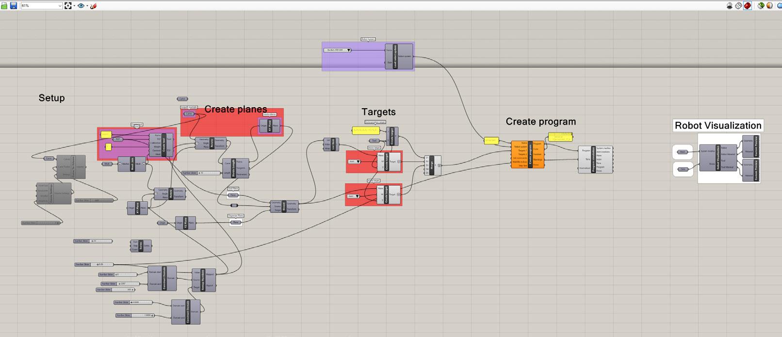
Hence through operating through a single software, the degree of rotation (controlled by the amount of ‘steps’ taken by the steeper motor) can be effectively tailored to adjust after each adjustment of the position taken by the robot arm. The overall script driving the path taken by the robot was achieved through the implementation of the ‘Robots‘ plugin for Grasshopper,
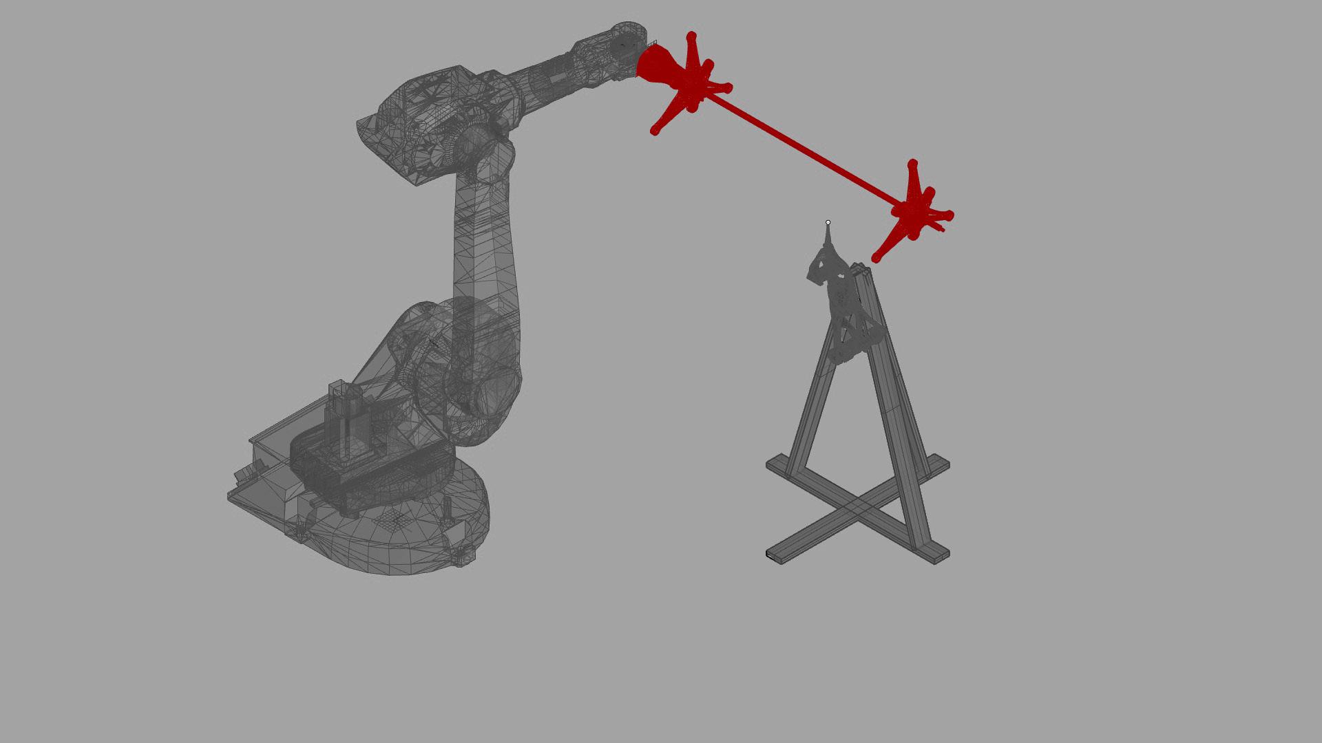
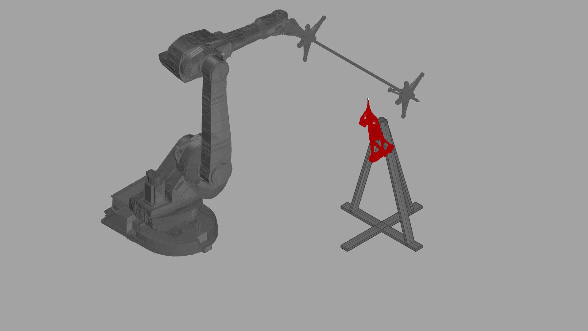
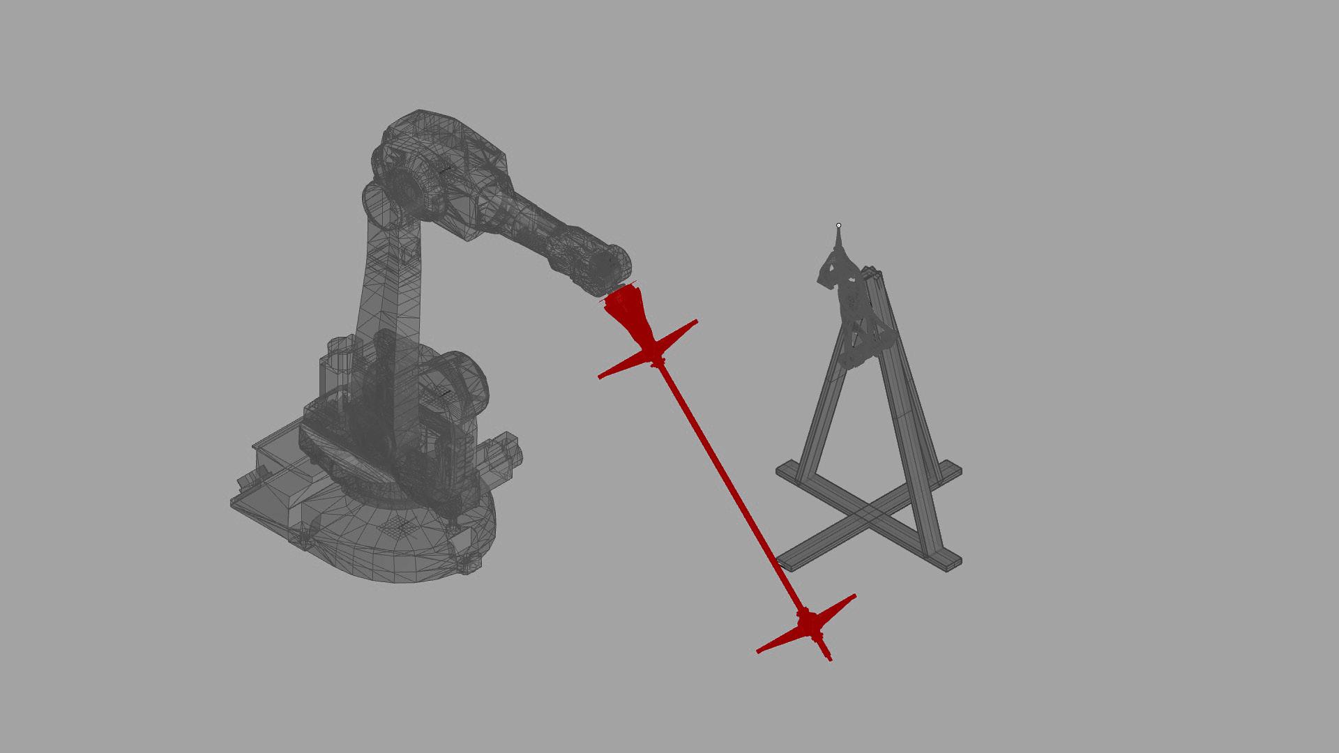
A1 A2 A3 TARGET POINT 3600 ROTATION AXIS
Figure 55: Authors image. Developed grasshopper script driving the tool path Figure 56: Authors image. Home position, first position for target plane, 360 degree rotation of stepper motor
3.6 60
Figure 54: Authors image. Firefly plug in to control steps rotation in stepper motor.
ADAPTABLE JIG
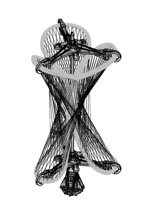
In order to fully embrace the qualities of the material and its elastic nature, the proposed prototype deviates from previous filament dispensing technique in that it proposes an adaptation of the form post manufacturing, though deforming the material via its elastic qualities.
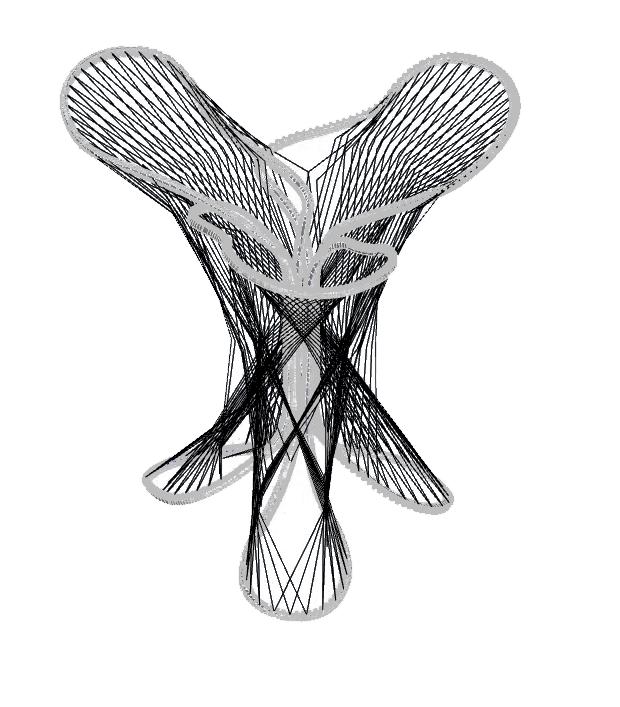
However in order to enable a flexible deformation of the prototype, the anchor points and jig upon which the filament is threaded must cater to the flexible nature of the material and post manufacturing sequence. Hence the following chapter investigates a series of analogue tests as to the flexible and elastic nature of an adaptive jig that subsequently impacts the logic developed for this manufacturing methodology.
3.7 62 63
Figure 57: Authors image. Elastic deformation post manufacture
4.1
ADAPTIVE SCAFFOLDING
In order to provide the rubber filament with a means of structure to support the overarching form whilst undergoing filament dispensation all whilst retaining the ability to flex and stretch post manufacture, an adaptive scaffolding method was opted for.
Existing controllable adaptive systems using flexible and elastic materials include ‘soft’ pneumatic designs such as soft robotics project spatial flux completed at MIT media lab by Carson Smuts et al (44). Whereby altering air pressure distributed into multiple pockets, alteration of the form can be proportionally controlled.
Soft robotics tend to use silicon as the core material to be inflated, due to its elasticity and ability to be cast from its liquid sate into solid. However as silicon is not biodegradable it was not considered as a viable material within this thesis. Therefore alternatively a ‘slit in tube‘ technique (45) was selected due to the ability of using pre cast & vulcanised natural rubber latex balloons.
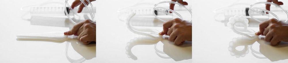
A review of ‘semi soft pneumatic actuators‘ research by Lee Beelding et al (45) displayed means by which inflating a latex tube enclosed by an external shell (a material with higher Young’s modulus) containing slits of different directions and lengths, produces a variety of motions, including bending, twisting, contraction, and elongation (45).
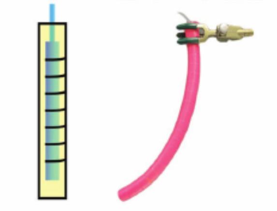 Figure 58: Carson Smuts et al. MIT media lab .spatial flux, soft robotics inflation. 2017
Figure 59: Lee Beelding et al. Slit tubes for semi soft pneumatic actuators. 2018
ADAPTIVE ASSEMBLY 64
Figure 60: Authors image. Single way air valve maintaining pressure of latex balloon inside of 3d printed ‘fila flex print. NR/ SR filament wrapped between ribs.
4.0
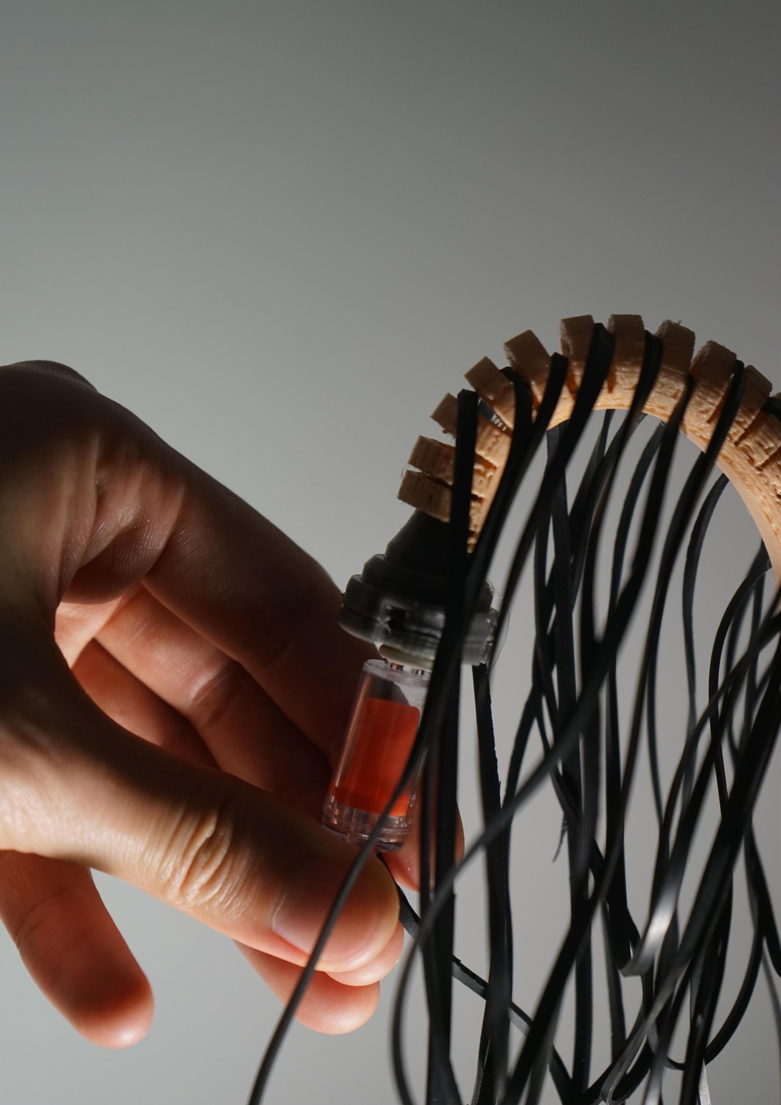
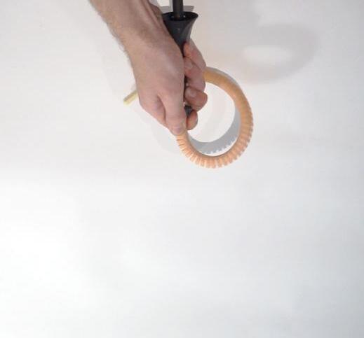
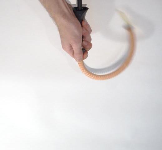
The ‘semi soft pneumatic actuators’ experiment was recreated using a natural latex balloon enveloped in a 3d printed ‘fila flex‘ rib to control the exact distancing of the slits (6mm). A constant increase in air pressure results in the deformation and subsequent bending of the enveloped balloon (Figure 61).
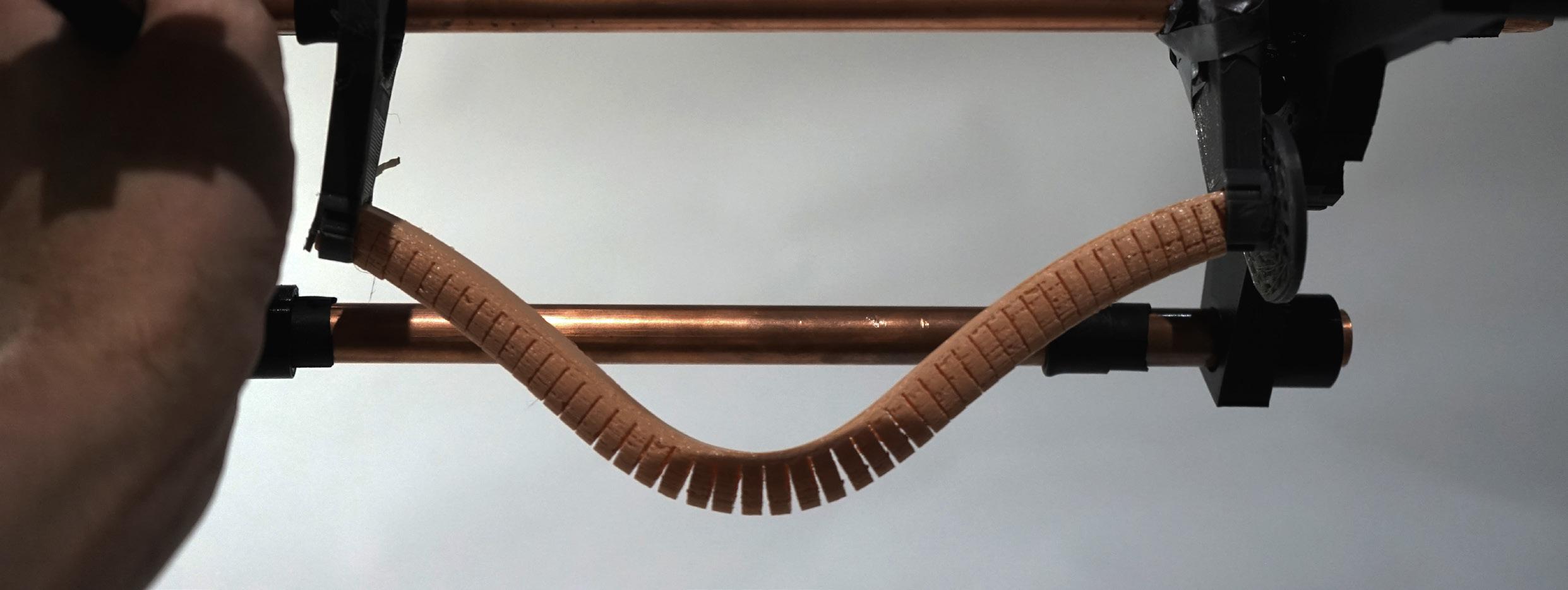
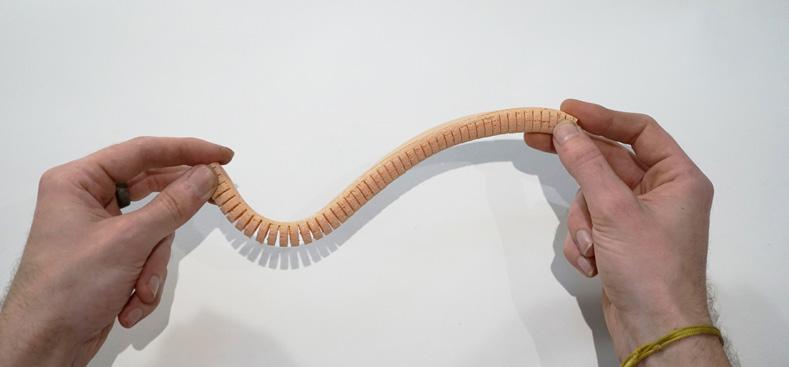
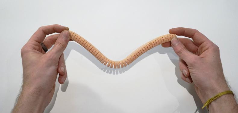
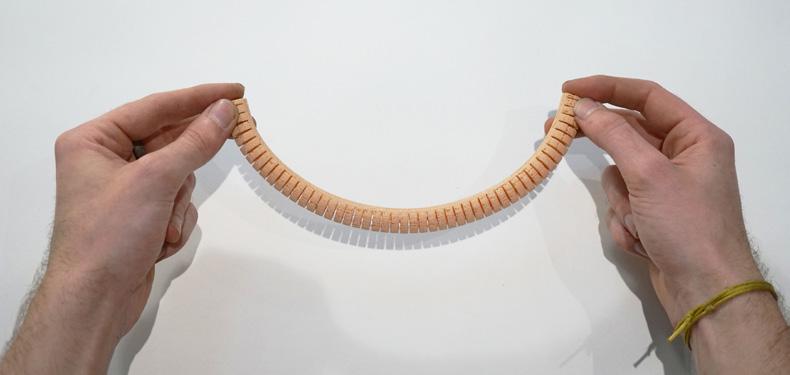
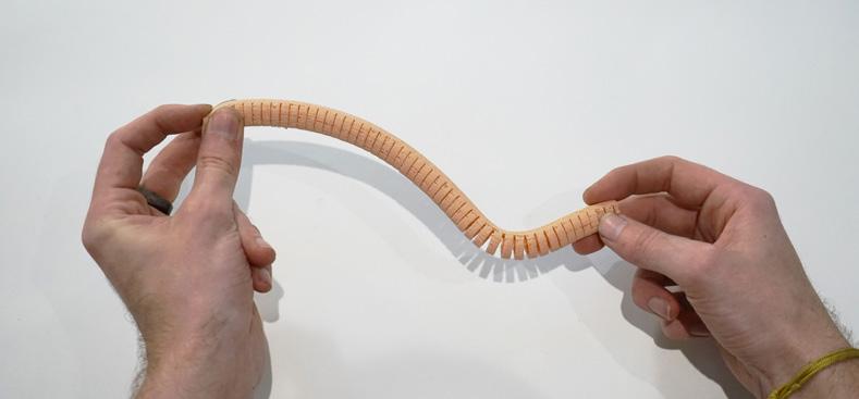
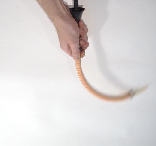
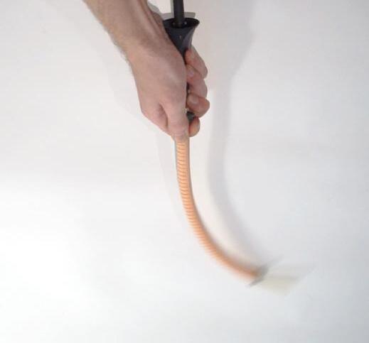
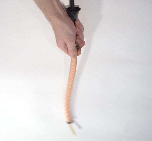
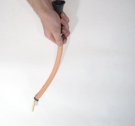
Although air pressure can trigger the motion of the balloon, its motion is restricted to the same form when the pattern is constant. However when varying the amount, angle and location of force along the rib, the location of curvature can be controlled (Figure 62).
Ribs used throughout this thesis do not contain natural rubber as the means to produce tailored natural rubber tubes are not available due to lack of access to the workshop during the COVID 19 pandemic. However the flexible properties are mimicked with synthetic alternatives.
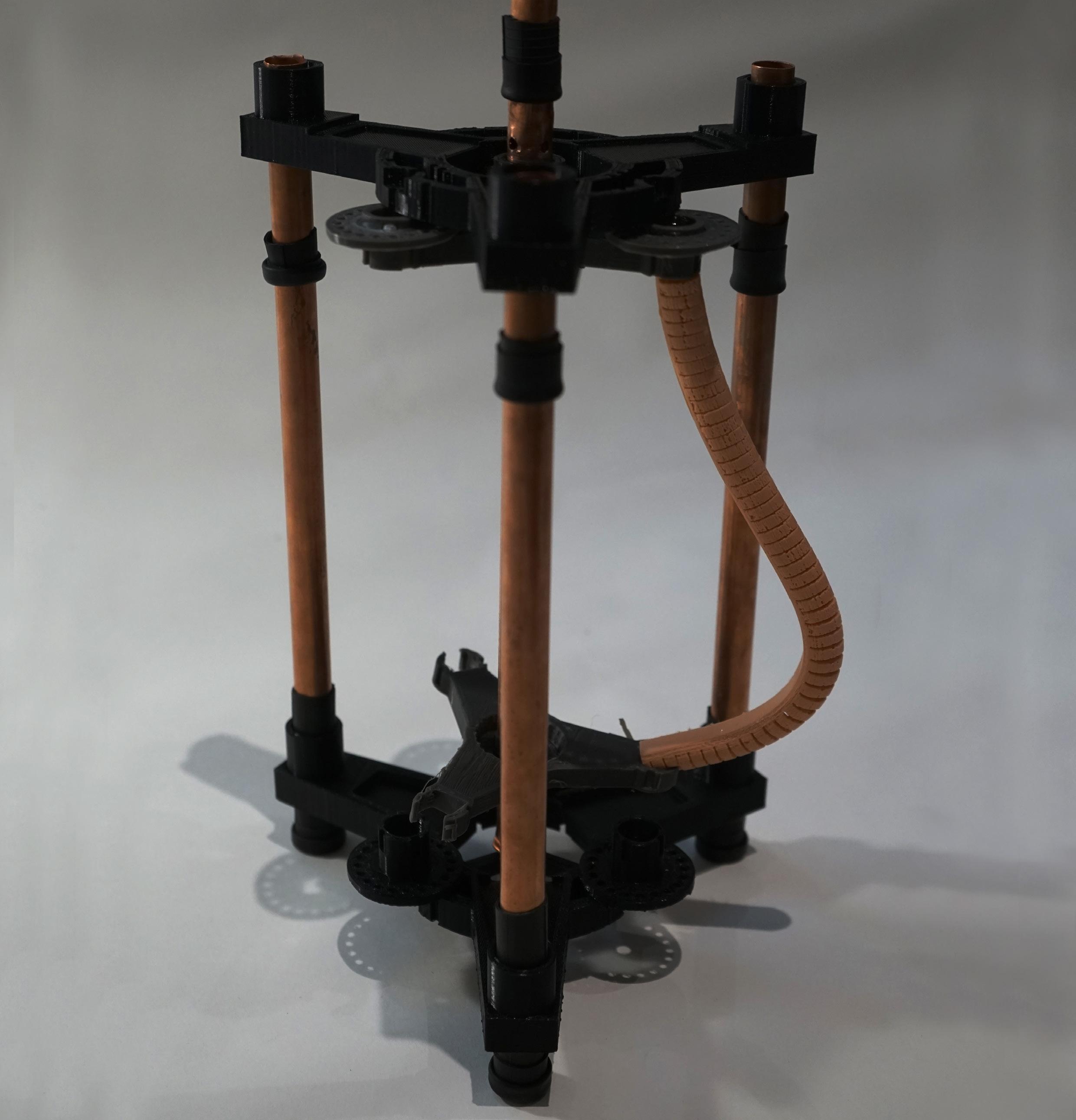 Figure 61: Authors image. Controlled deformation of ribs through increase of air pressure inside inner latex balloon
Figure 62: Authors image. Controlled deformation of ribs through altering force
Figure 62 Authors image. Vertically placed. Sagging shape taken by ribs due to gravity.
Figure 64: Authors image. Altering ribs shape through stretching inner latex balloon. (Next page)
Figure 63 Authors image. Horizontally placed. Sagging shape taken by ribs due to gravity.
Figure 65 Authors image. Altering ribs shape stretching inner latex balloon. (Next page)
66
Test Hanging_A: Unaltered
4.2
VARIANCE IN STIFFNESS THROUGH INCISIONS
The natural curvature of an extruded rubber rib ‘scaffold’ was tested on a larger scale appropriate to the scale proposed for the developed prototype ( ranging between 120-140mm). In the first iterative test of these ribs EPDM extruded 20 mm diameter rubber car seal strip were used due to availability, pre extruded hollow profiles and similar flexible qualities to that of some natural rubber composites.
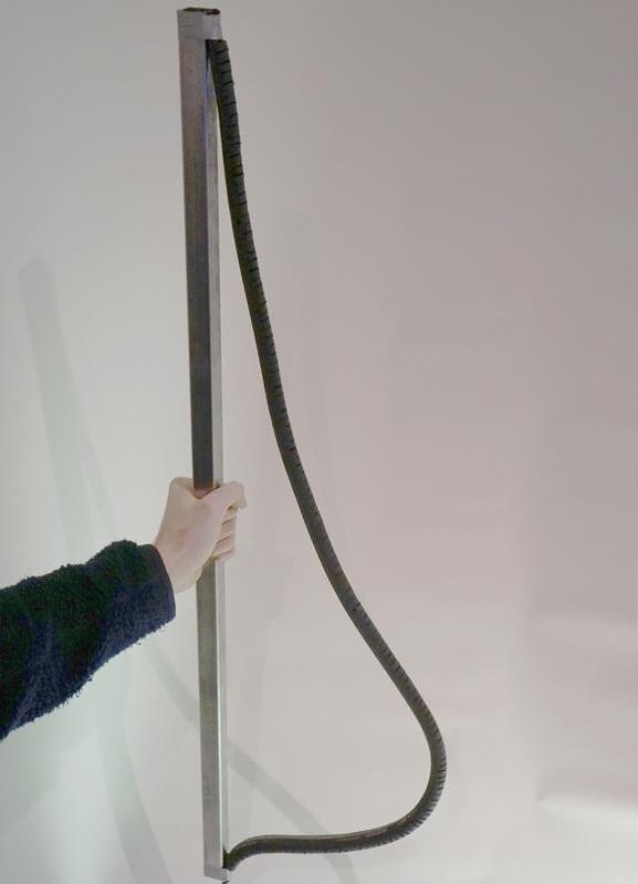
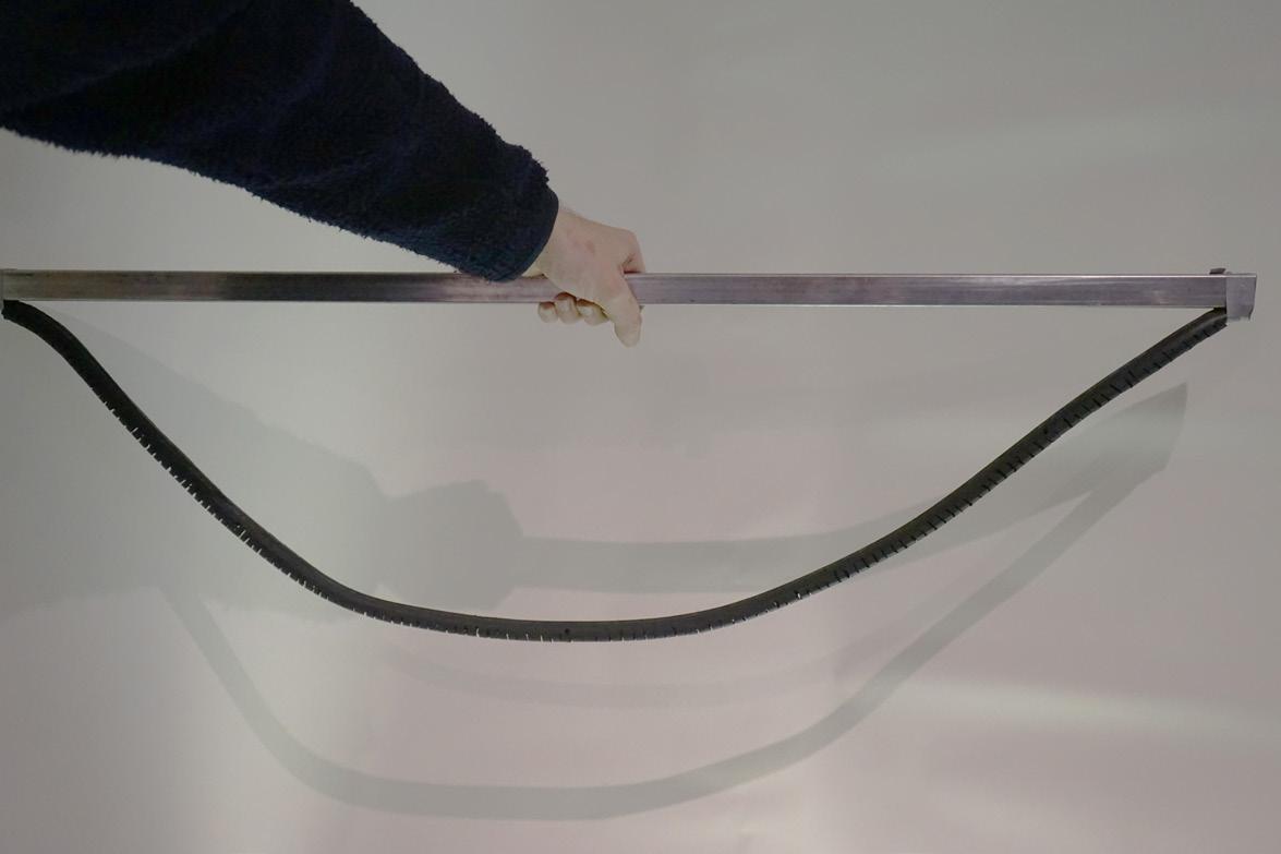
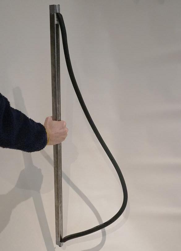
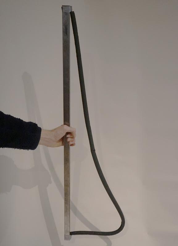
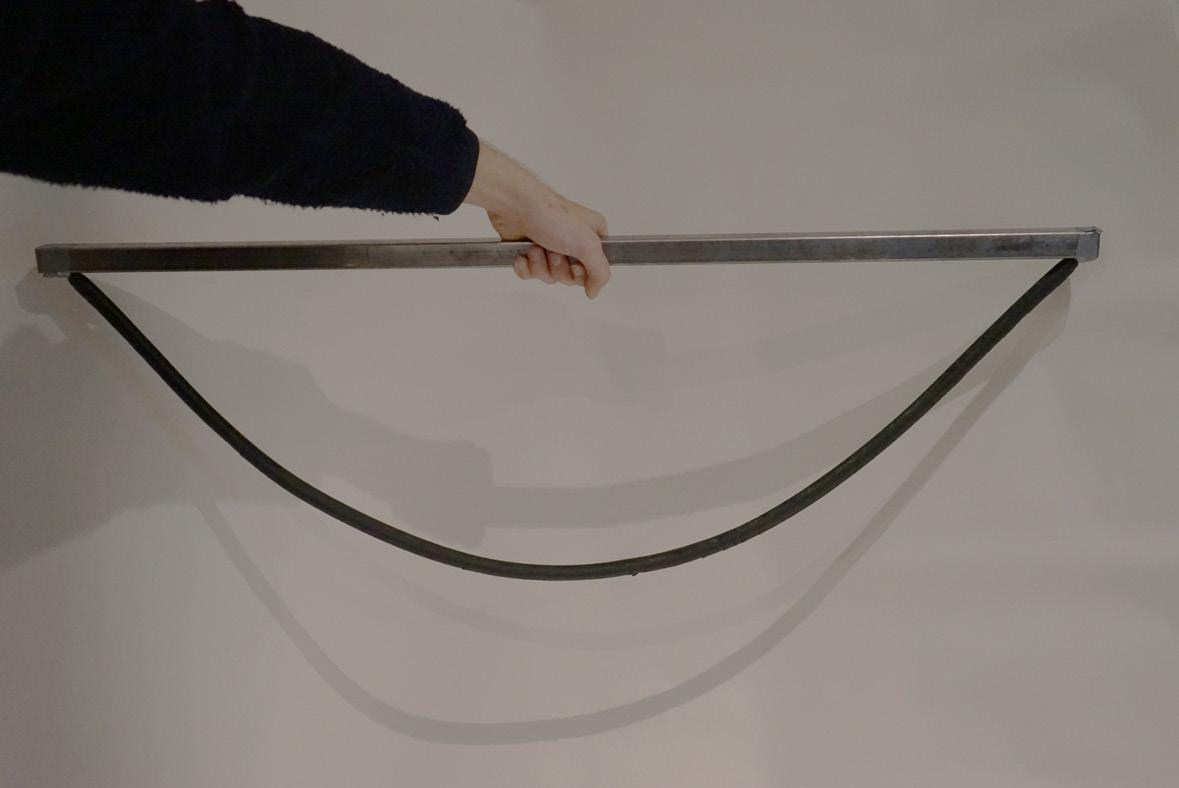
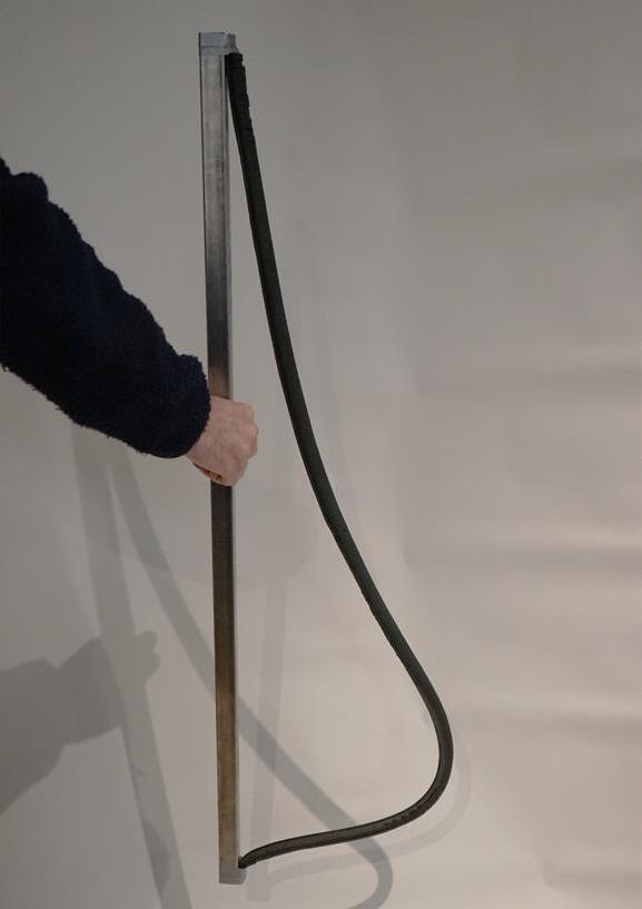
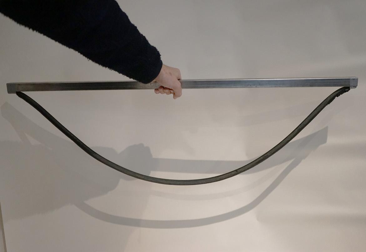
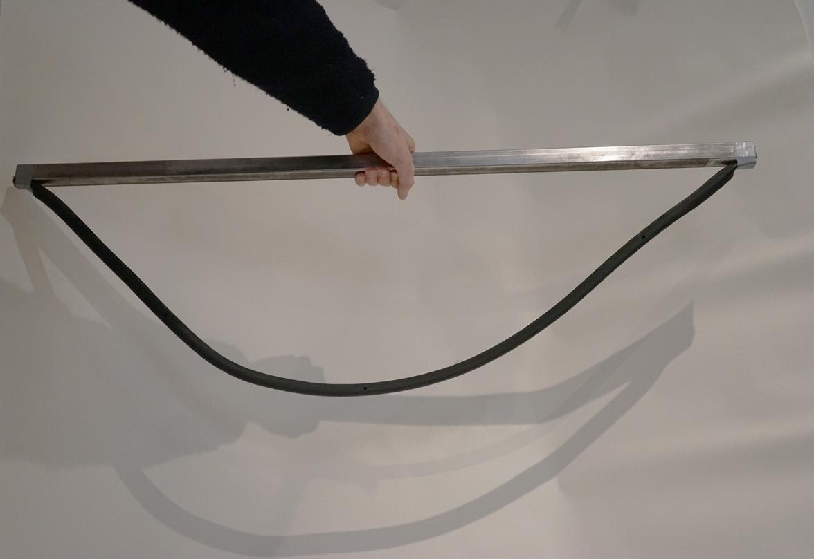
The profile was subjected to a series of incisions of varying depths and spacing. Overall observations consisted that in its uncut state, the synthetic rubber profile when placed horizontally, displayed a high degree of curvature at its centre and when placed vertically, the degree of curvature is greatest lower down.
When incisions were added and backing removed, the stiffness greatly decreased the curvature at the points of restraint whence horizontally restrained, whilst the overall curvature when placed vertically was less pronounced.
Test Hanging_B:
The core issue with the first iteration of chosen rubber profiles was a lack of stiffness when slits were inserted, and subsequently did not create the degree of curvature required for the ribs top open sufficiently for filament to be placed.
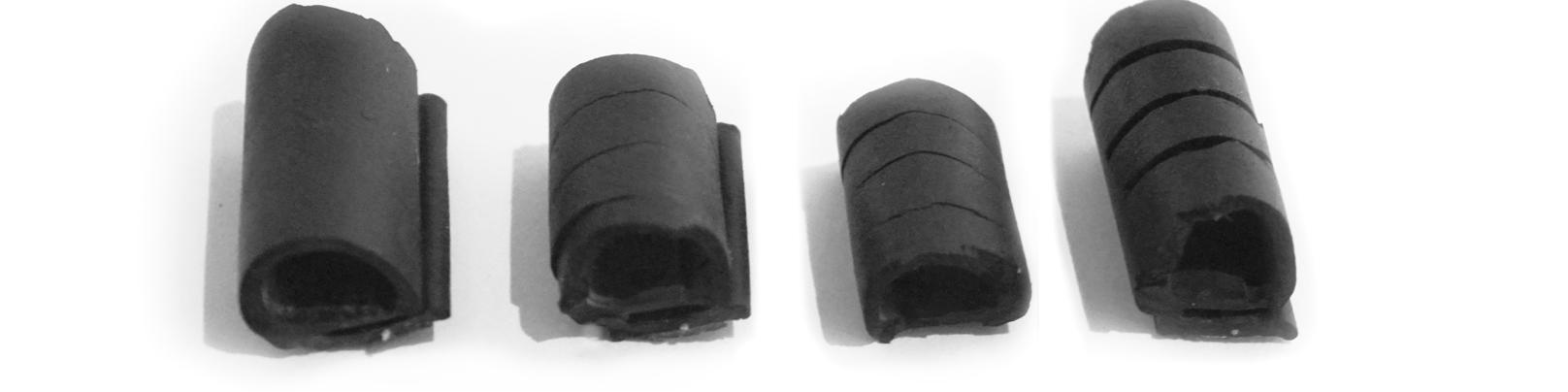
This issue was overcome by reducing the length so there is a higher radius to length ratio, placing the point of retention further along the supporting device, reducing depth or amount of incisions and increasing the stiffness of the profiles back.
Test Hanging_C:
Altered, cut at 5 mm increments (+1mm), with 1.5 mm (+-1mm) removed in between
Altered, cut at 6 mm increments (+1mm) Figure
Test Hanging_D:
Altered, cut at 6 mm increments (+1mm), with backing removed
Figure 68.a: Authors image
Figure 68.b: Authors image
68.d: Authors image
Test Hanging_C: Profile Test Hanging_D: Profile Test Hanging_B: Profile Test Hanging_A: Profile
Figure 68.c: Authors image
Figure 69: Authors image. Altering point of restraint to alter curvature (Next page)
Figure 67: Authors image. incisions within profiles to alter stifness
Figure 66: Authors image. Curvature zoning via restraint positioning
Figure 70: Authors image. Altering point of restraint to alter curvature (Next page)
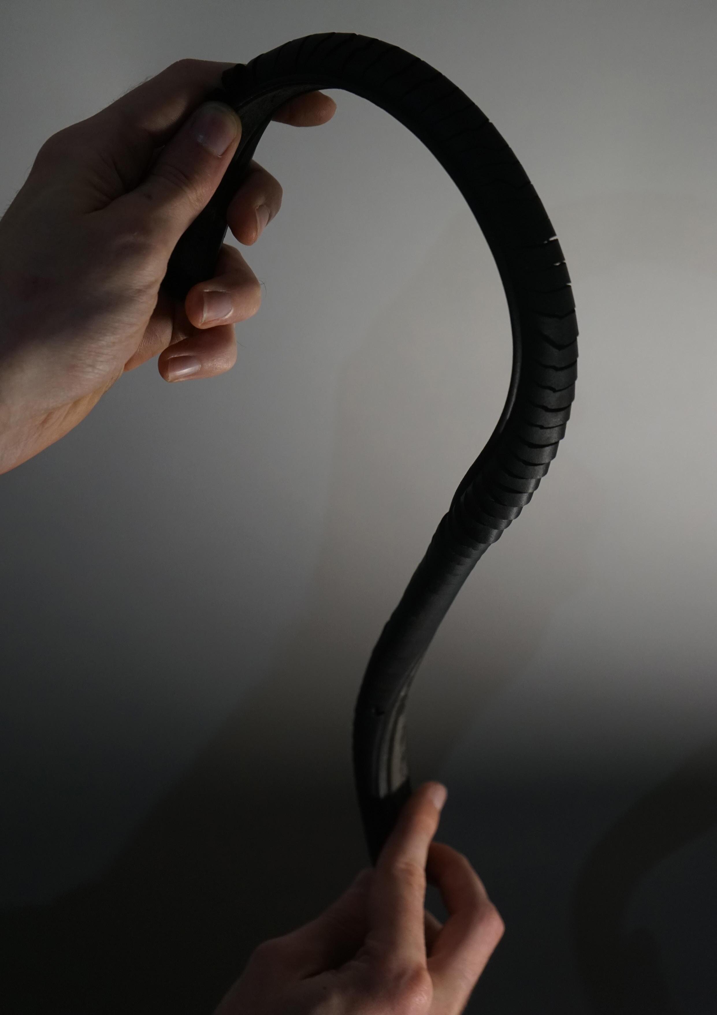
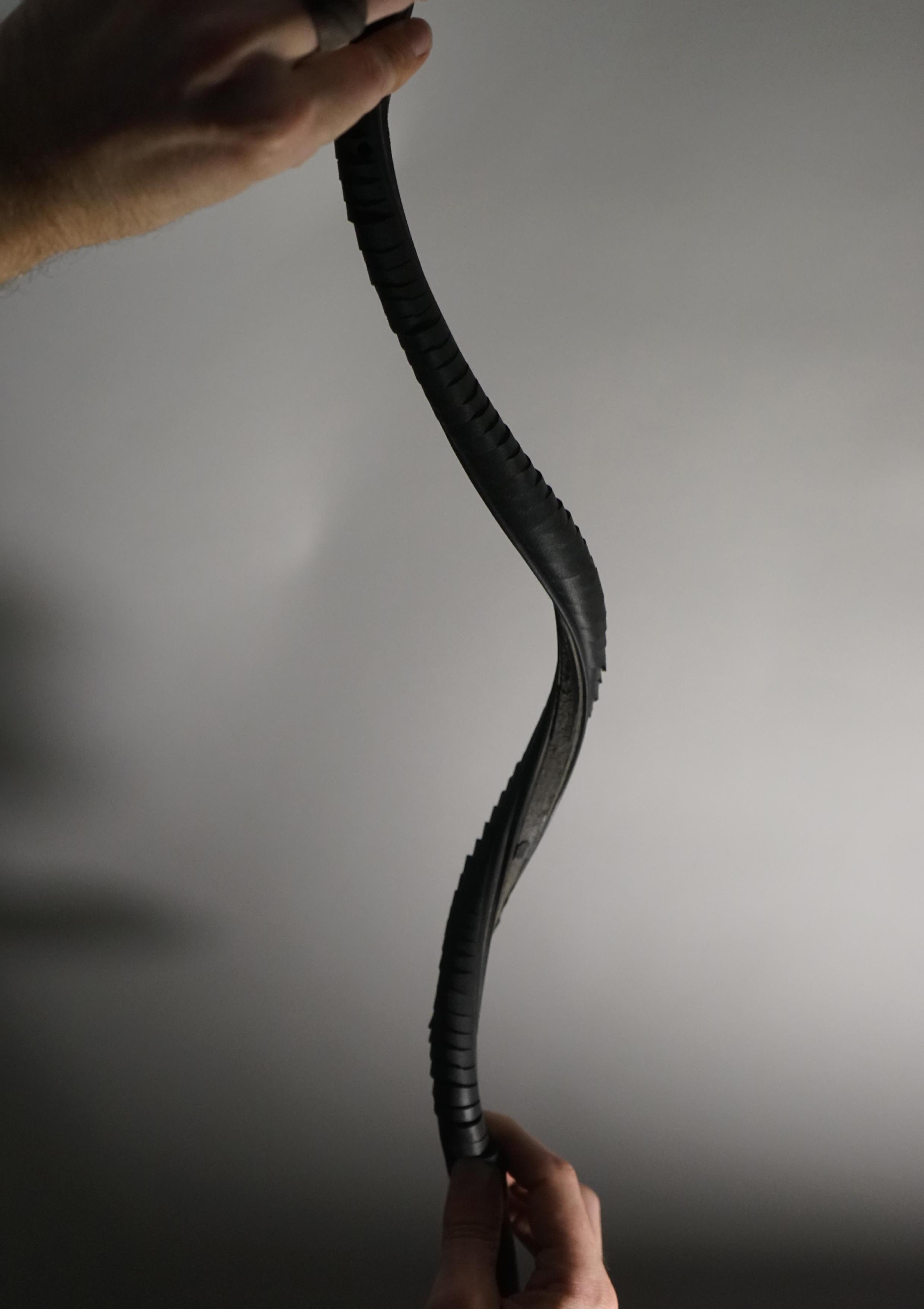
A second synthetic rubber extrusion (EPDM car seal) was used to test the curvature of the ribs with a stiffer back. The backing of this sample contained 1 mm spaced aluminium fixings used to stiffen the seal (Figure 71). The solid synthetic rubber back was also manufactured in a circular resting pattern resulting in an torsional curvature when held without applied force.
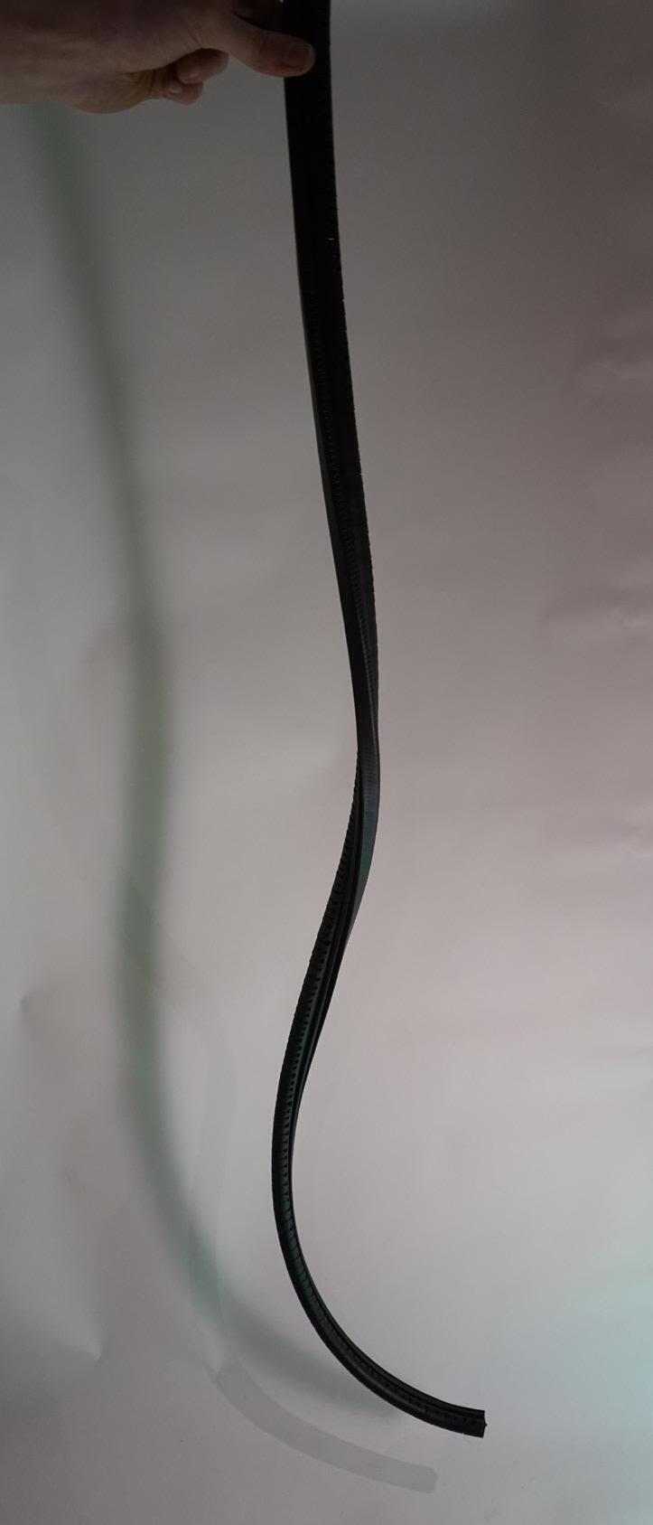
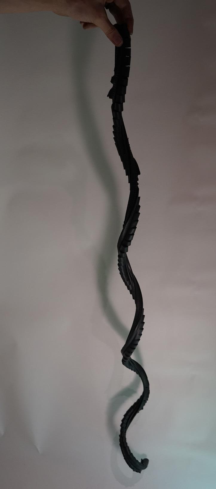
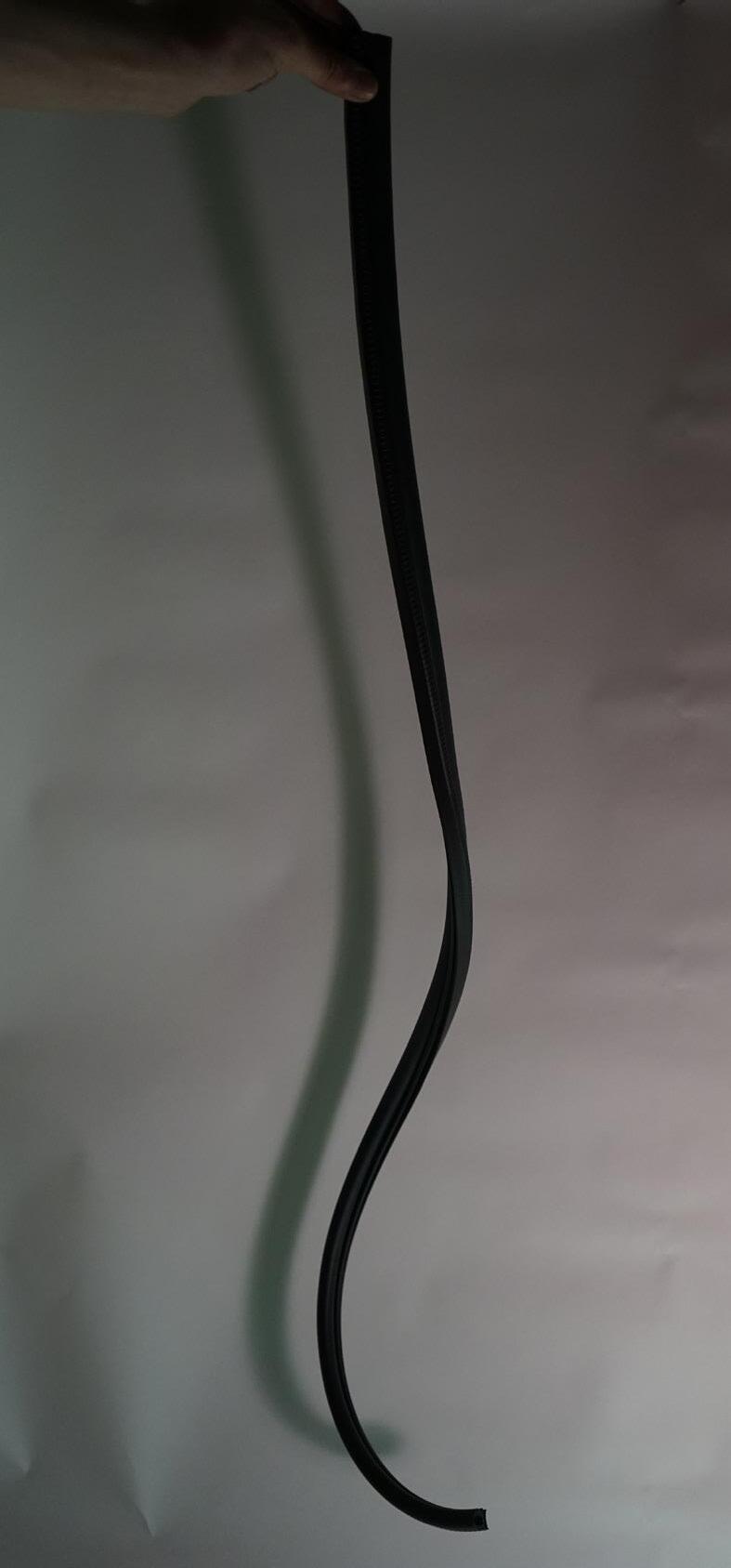
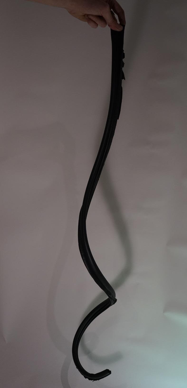
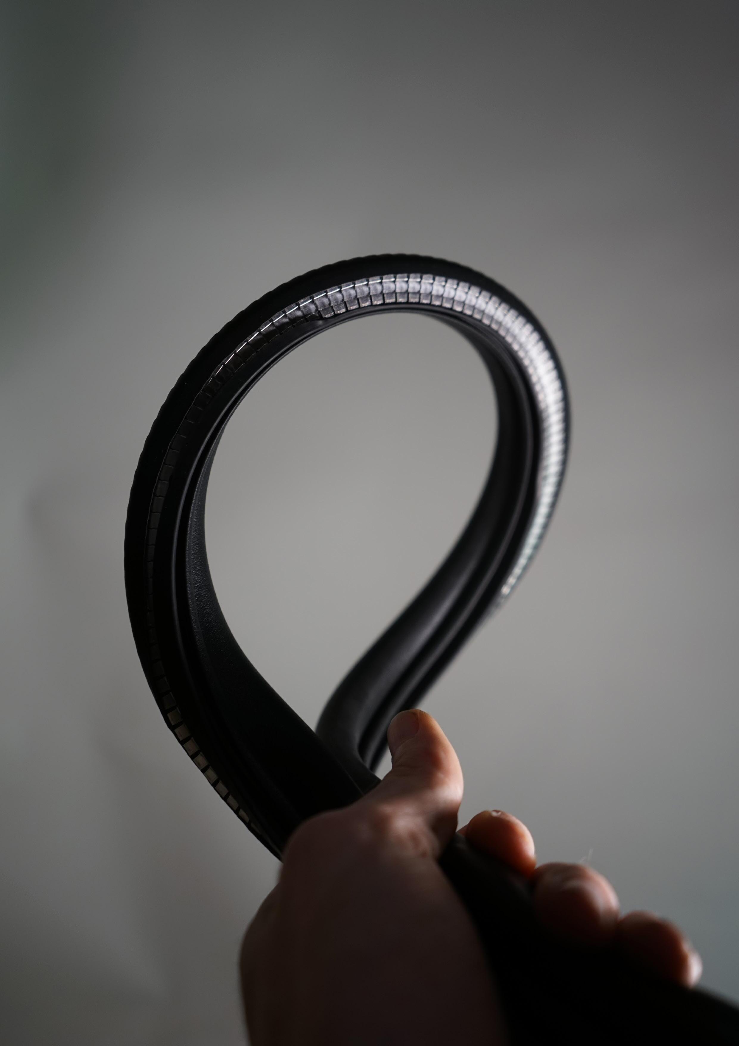
The unaltered seal (Test backing_A) retains a mostly vertical position towards the point of fixing, however begins to curl in on itself towards the lower end. Whence incisions were inserted on this sample (Test backing_B) only a negligible change in the curvature was noted.
Once the aluminium fixings were removed from the backing of the sample, the reduction of stiffness in the seals spine resulted in amplifying the seals radial curvature creating multiple rotations of curvature, as seen in test backing_C. This effect is further amplified when incisions are added as displayed in test backing_D
The resulting programmable deformation of the rubber profile can hence be tailored in to varying degrees of stiffness and form by altering the amount of cuts placed as well as the prominence of an inserted backing along the rib.
Figure 72.a: Test Backing_A: Unaltered
Figure 72.c: Test Backing_C: No incision, aluminium fixings removed from backing.
Figure 72.b: Test Backing_B: incisions every 8mm, with holes below each incision
Figure 72.d: Test Backing_D: Incisions every 10mm, with aluminium fixings removed.
Figure 71: Authors image. Altering point of restraint to alter curvature
4.3
DEFORMATION VIA PNEUMATICS
In order to drive the deformation of the rib via pneumatic driven inflation as tested at the beginning of this chapter, at a scale suited to the developed prototype, a series of natural rubber balloons were joined together via custom 3D printed fasteners.
However, the disproportional air flow along the 4 joined balloons resulted in an uneven distribution of force along the rib, causing the balloon to protrude in areas where either the incision was placed to deep, or the concentration of force would result in a tearing of the cut, hence allowing the balloon to protrude.
In effect although the principal displayed at the beginning of this chapter worked at a smaller scale with a single balloon and precise cuts due to the 3D printed accuracy of the produced rib, the degree of deformation could not be replicated.

It can be determined to rectify this issue, a single long custom manufactured balloon would distribute an even and constant pressure. Additionally the creation of an accurate rib with precisely placed cuts such as the 3D printed format would allow for a more accurate controlled deformation.
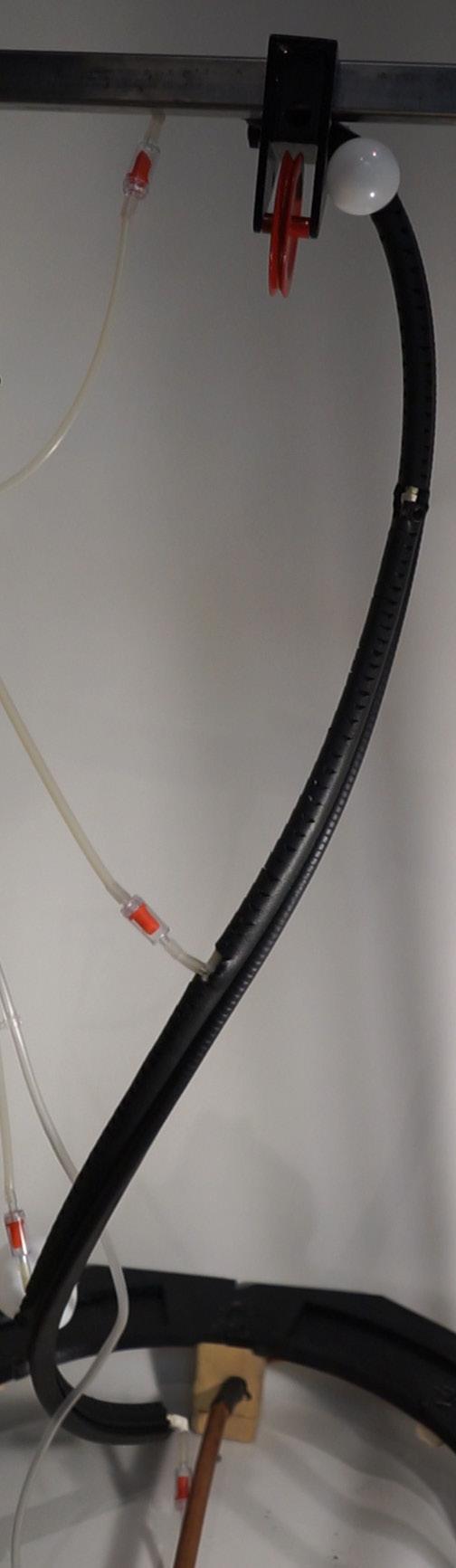
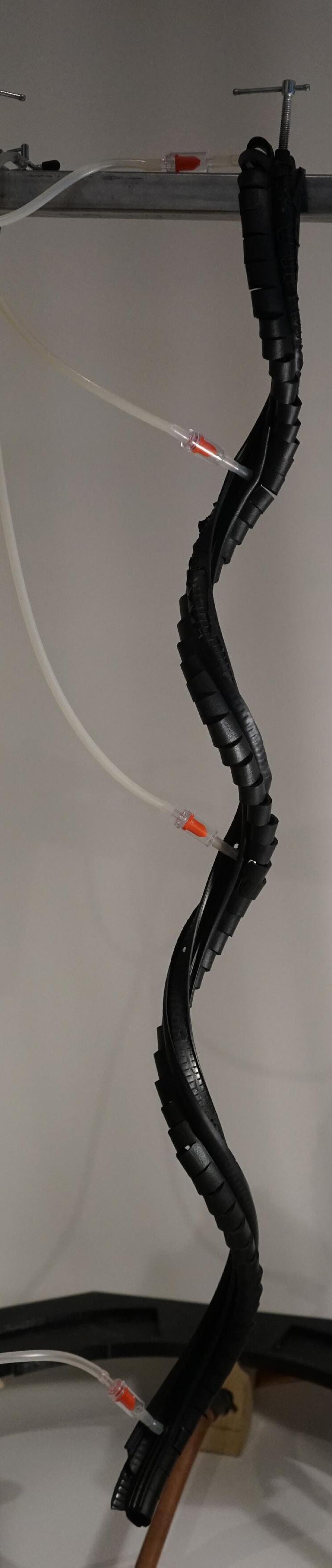


 Figure 73: Authors image. Rubber balloon connection.
Figure 74: Authors image. Multiple natural rubber balloons inflated Figure 75: Authors image. un-inflated rib
76
Figure 76: Authors image. Inflated rib
RIBS AS ANCHOR POINTS
The application of the incisions along the extruded rubber rib are used as a dual purpose of both dictating the inflated form of the pneumatically triggered rubber tube as well as acting as a means in which to place the filament during the robotic dispensation process.
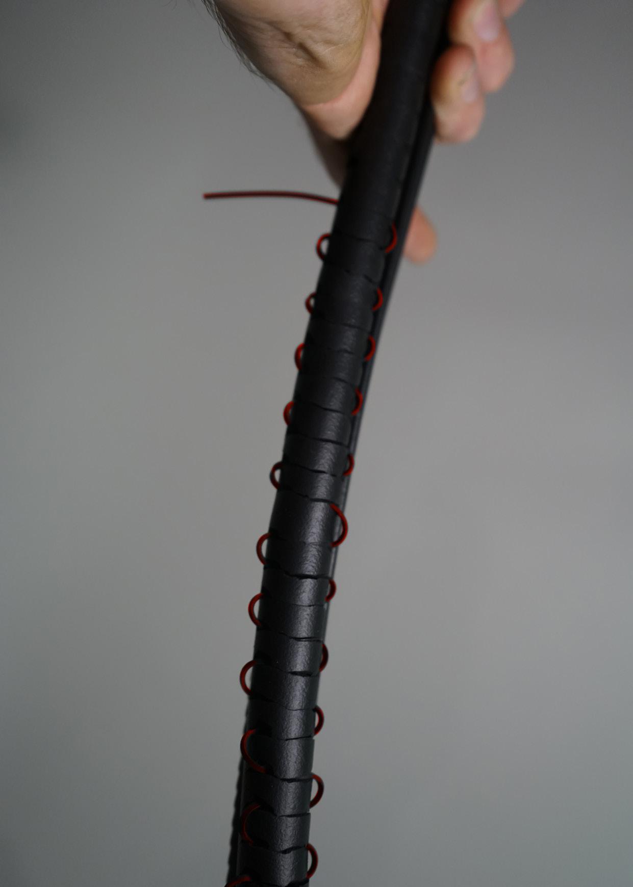
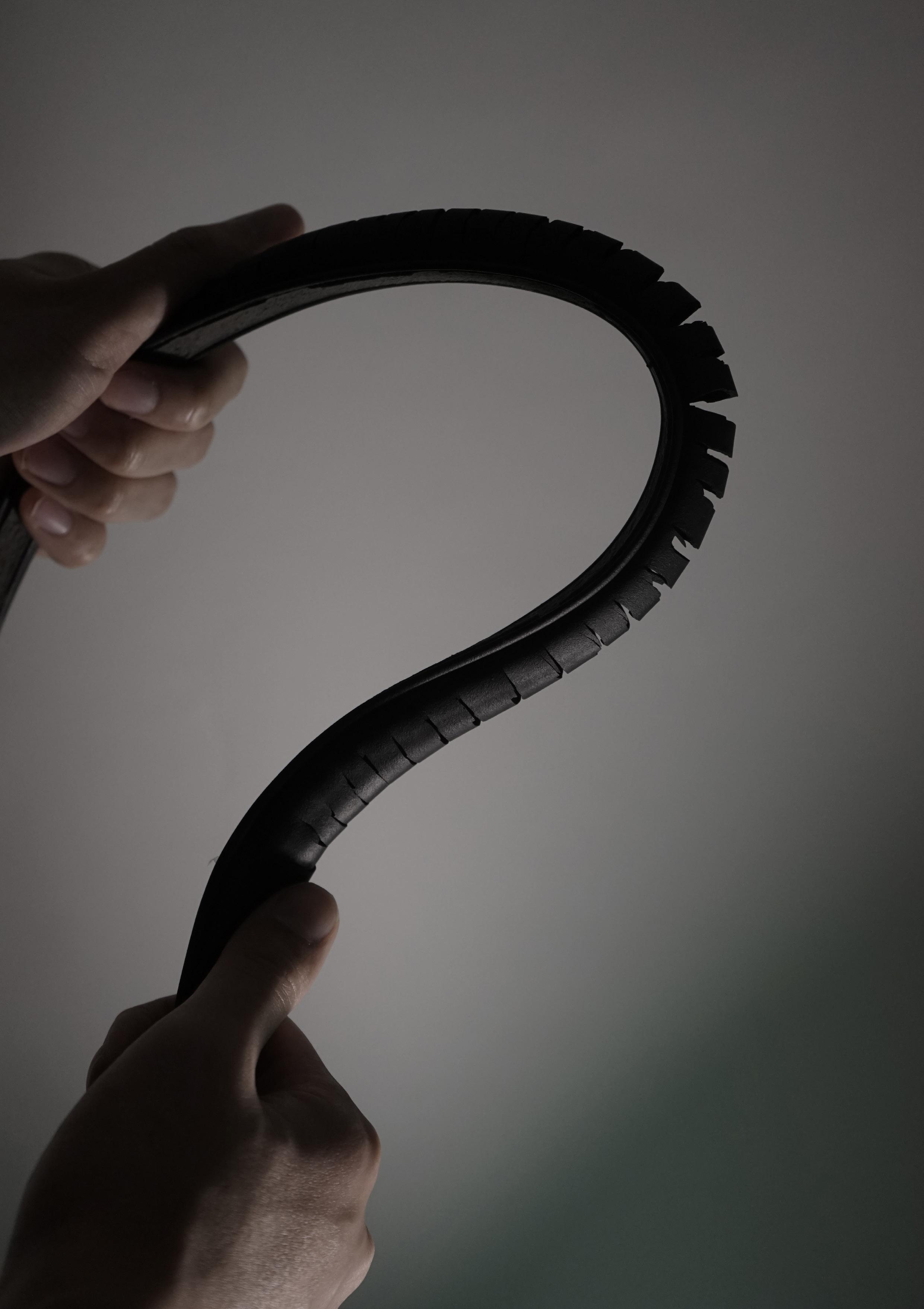
From the analogue tests conducted it became apparent that when an applied constraint was placed to produce a high degree of curvature, the incision would become wider (Figure 78.a). The created openings then effectively allows for enough space to place the rubber filament whilst loosely holding it in place (Figure 78.b).
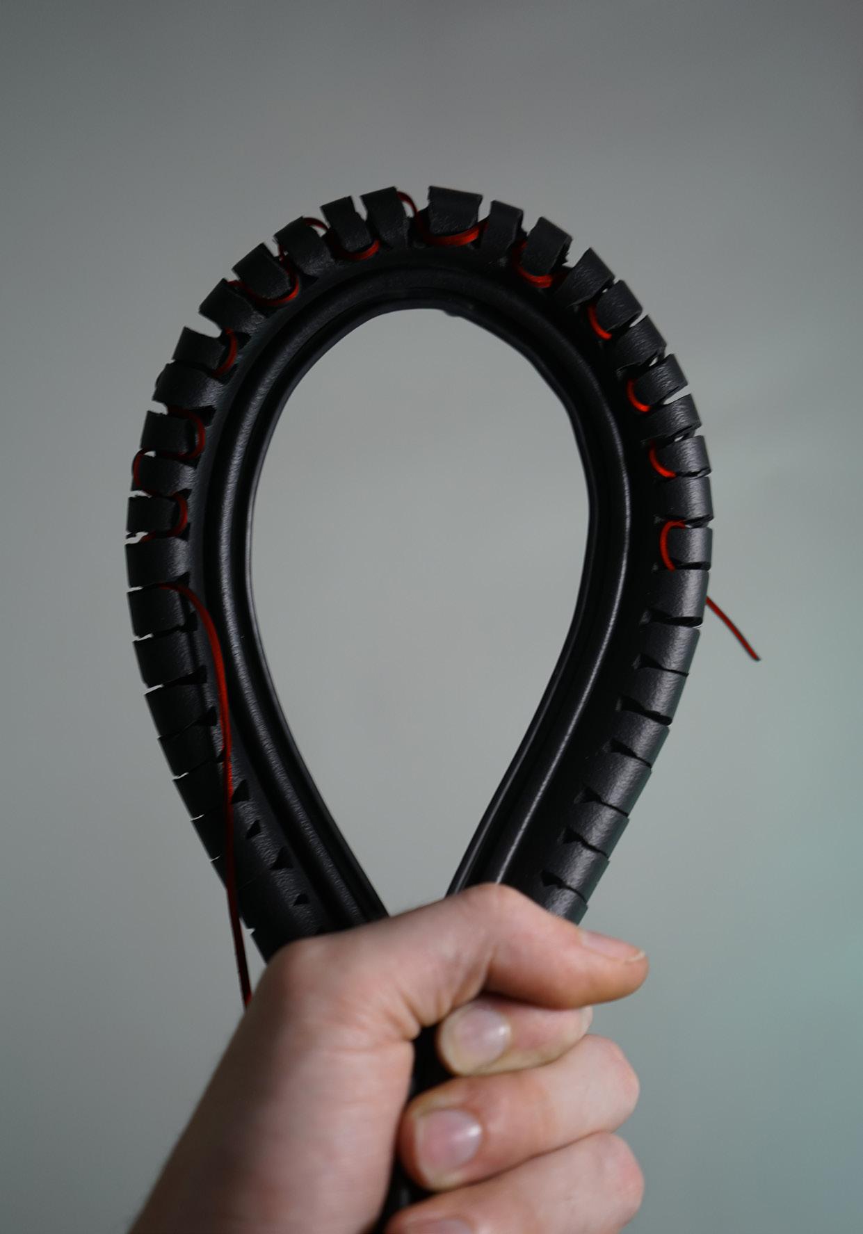
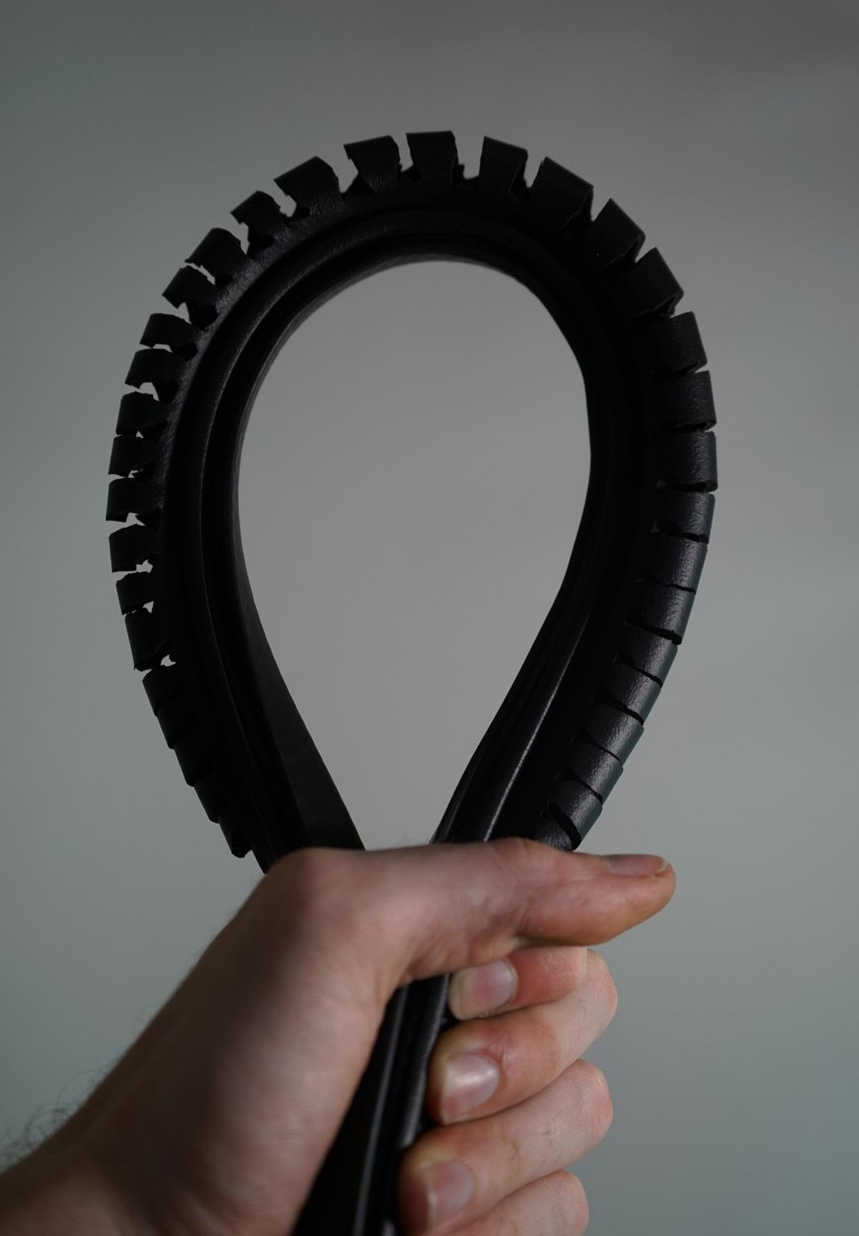
The flexible ability of the material, and its subsequent ability to alter its form allows the rib to then ‘lock‘ the filament in place either returning to a lesser degree of curvature (Figure 78.c) or inserting a twist in the curve (Figure 78.d) effectively closing the gaps previously created.
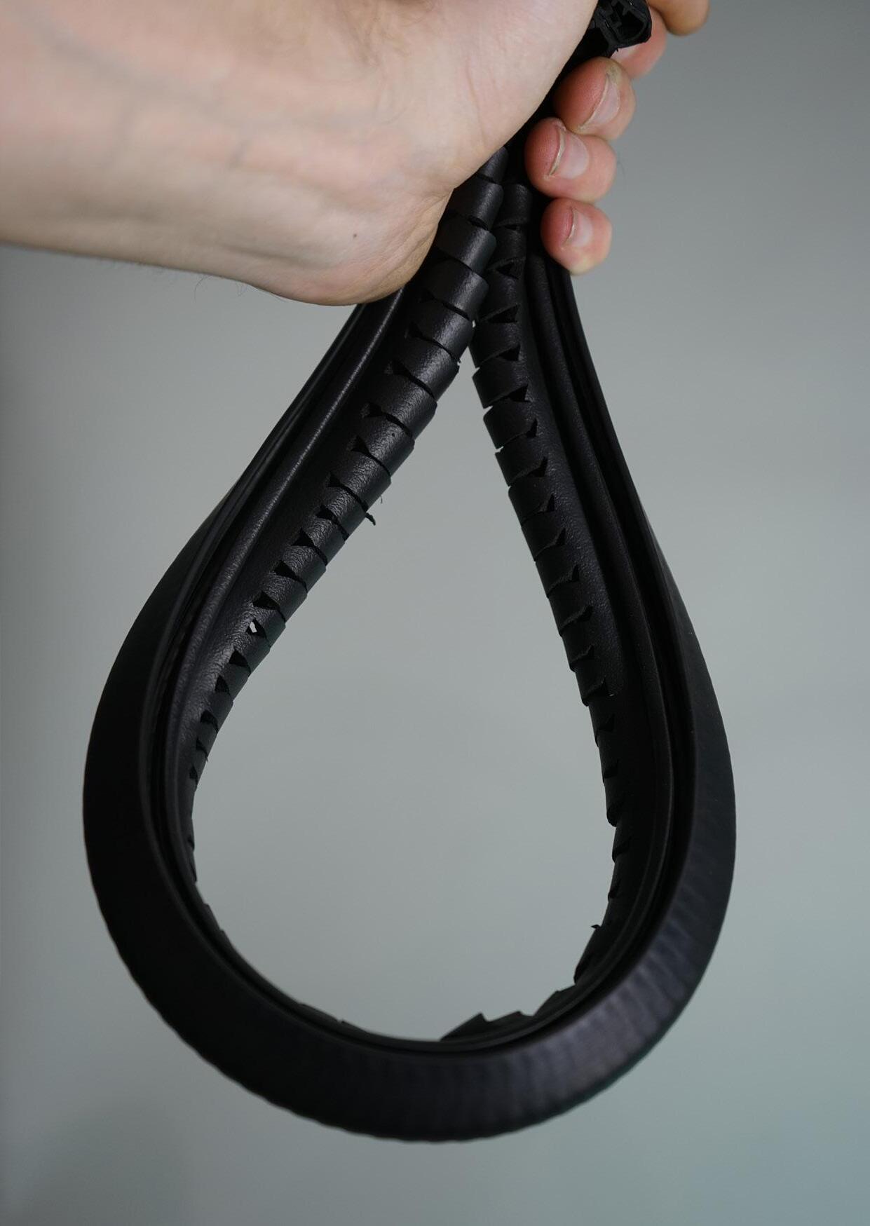
During the testing of the placement of the incisions, several parameters were concluded in determining the optimised pattern to enable its pneumatic inflation and performance as a filament holder.
- Placement 10mm apart of incisions to allow control of curvature through pneumatics
- Incision depth half the width of the tube to prevent tearing on either end
- Insertion of wider gap at the end of the incision to allow the filament to hold in place.
- The use of a profile with strengthened backing to maintain stiffness and exaggerate the opening of the incisions.
4.4 A C B D
Figure 78.a: Authors image. Ribs opened
Figure 78.c: Authors image. Ribs closed
Figure 78.b: Authors image. Filament inserted
Figure 78.d: Authors image. Filament locked
78
Figure 77: Authors image. Filament slotting into ‘open‘ ribs
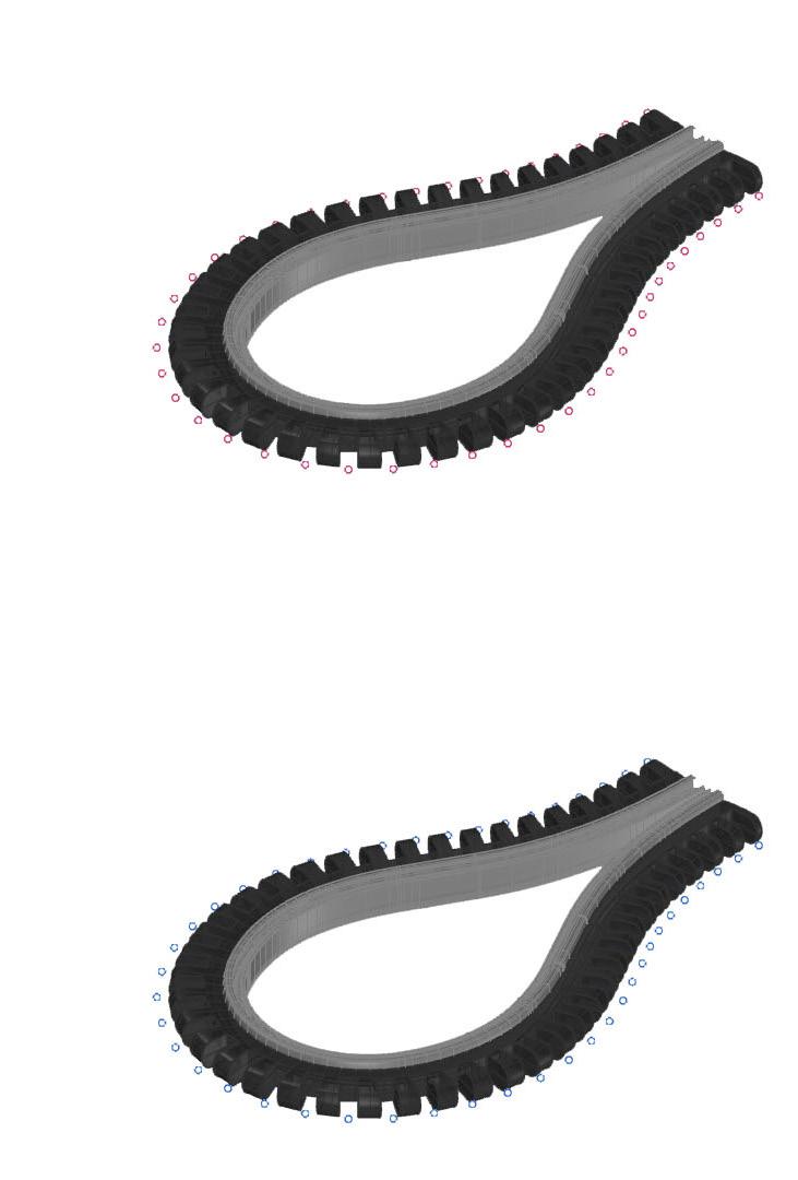
In order to create a three dimensional geometry, two or more ribs are needed to allow the filament to traverse over a void space. Figure 79 shows the manner of weaving between the outer facing ‘open‘ incisions created by the forced curve. Resulting in the outer incisions to become anchor points or ‘targets‘ for the robot arm to position itself to and subsequently lodge the filament.
1 2
Figure 79 Authors image. Anchoring filament along ribs
80
Figure 80: Authors image. Displaying open ribs
To secure the hold over the placed filament, once the thread has been placed, the flexibility of the rib and elasticity of the filament subsequently allows it to reverse its curvature, causing the incisions to be facing inward. This reversal of curvature subsequently causes the incisions to close up, securing the hold of the placed filament.
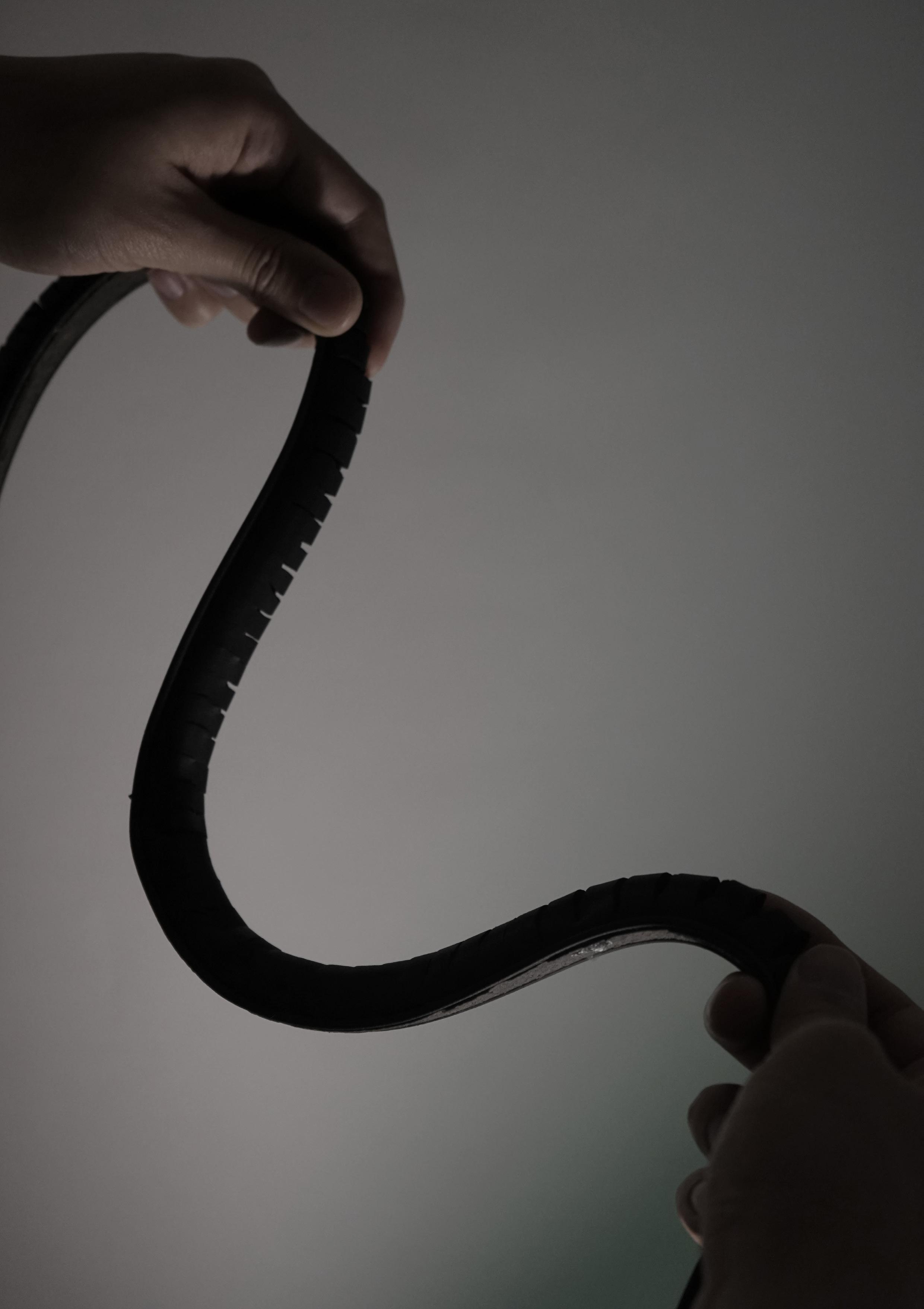
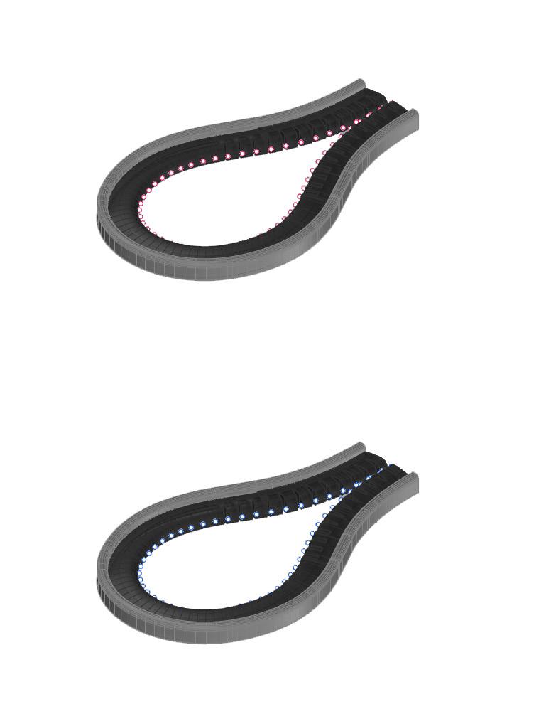 Figure 81: Authors image. Reversing locked ribs
Figure 82 Authors image. Displaying locked ribs
82
Reversed outer backing
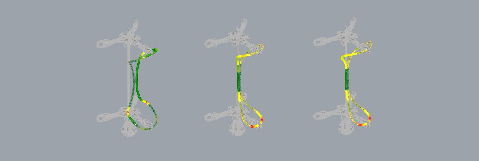
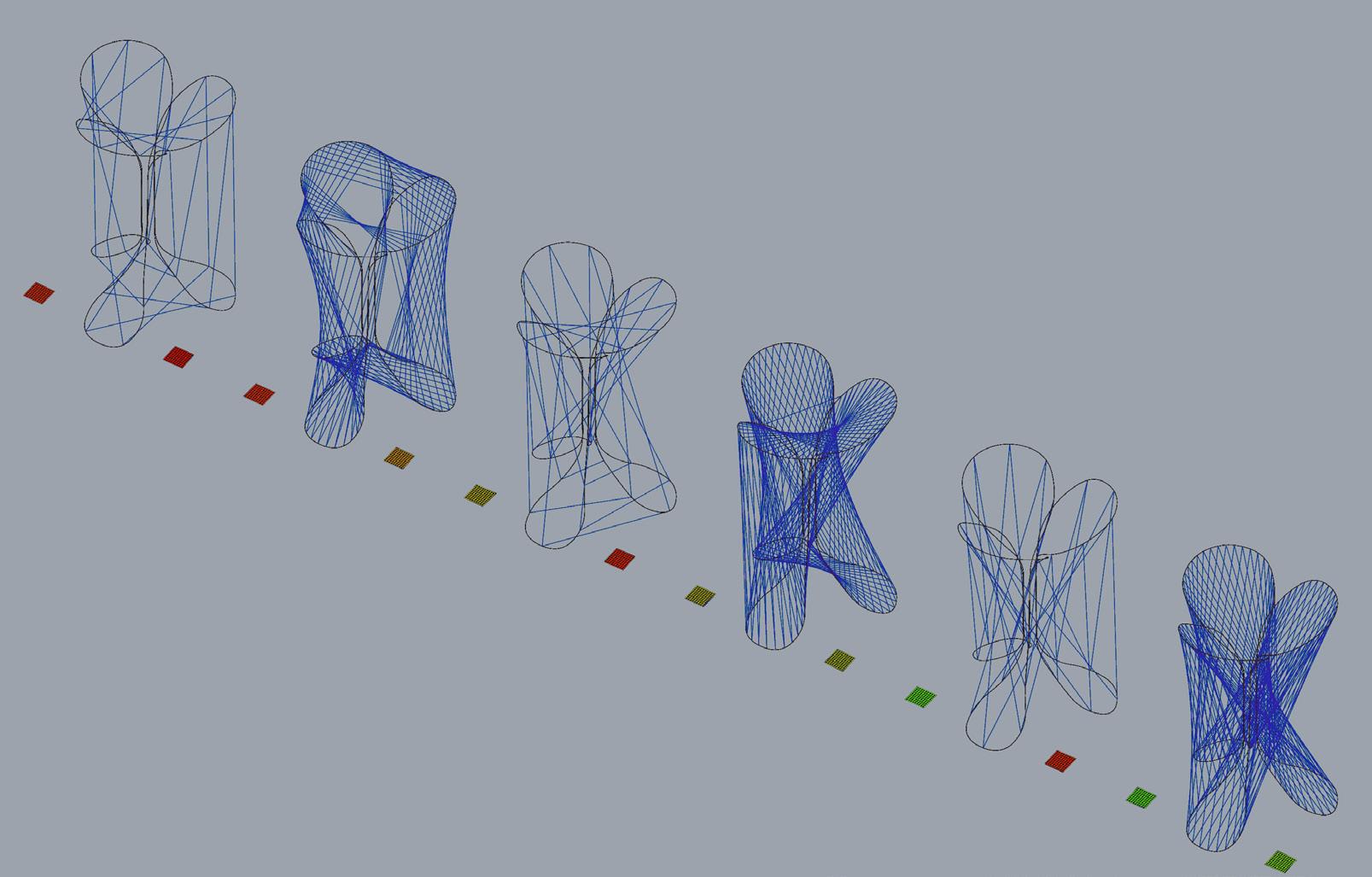
In order to trigger the opening of the ribs a tight curve must be introduced at specific point along the rib. In tangent to analogue test of the materials behaviour, the curvatures taken were approximately translated into rhino and analysed via grasshopper, whereby the intensity of the produced curvature is determined through proportionally distributed colour. The subsequent feedback of the positioning of highest degrees of curvature thus contributed in determining the shape of the rib.
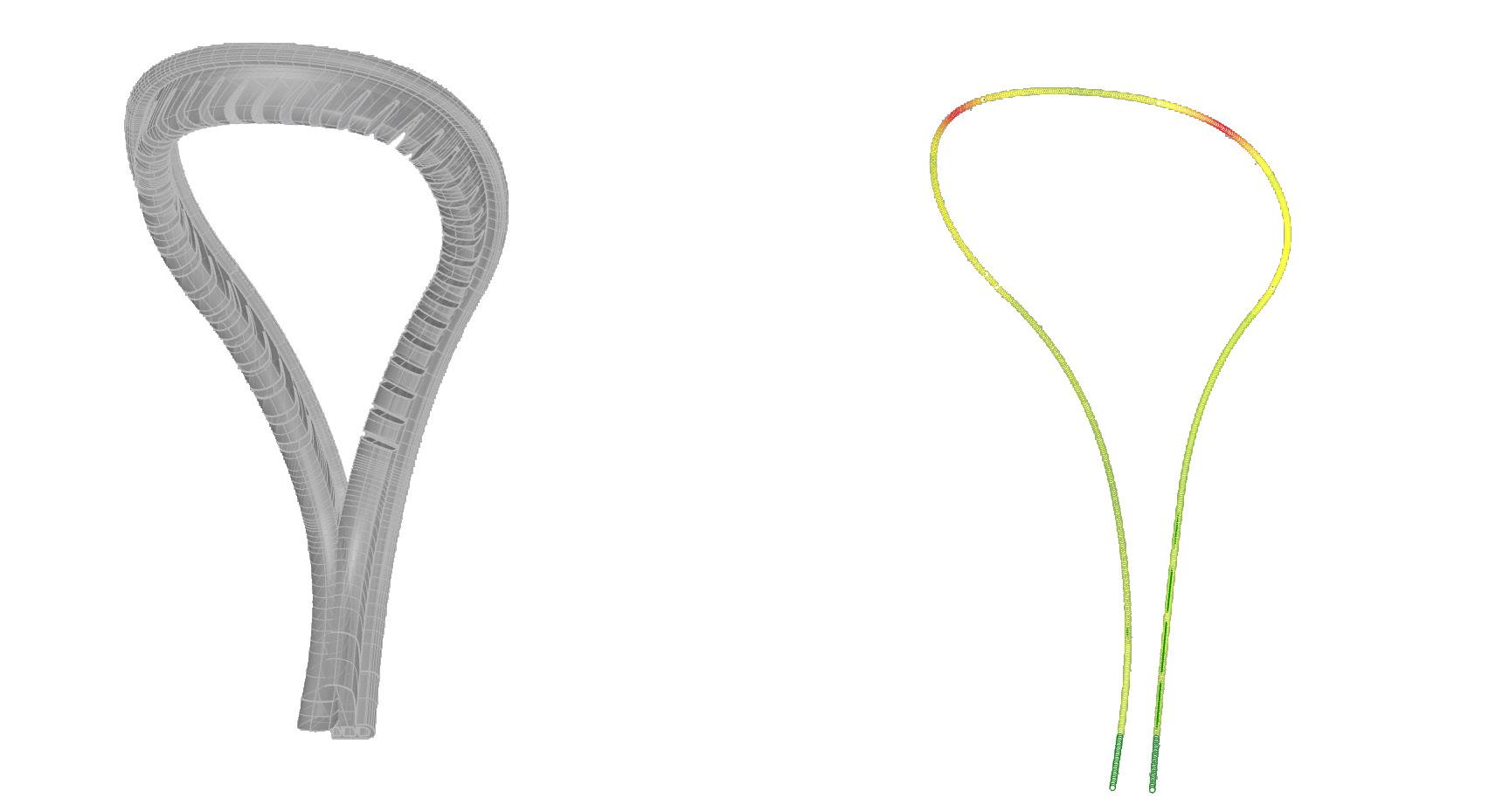

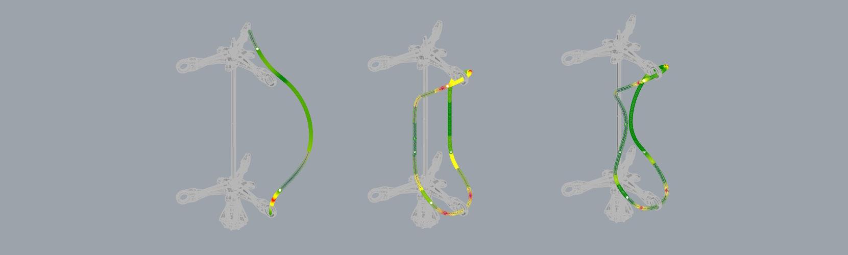
Yellow represents areas that are sufficient in opening the ribs
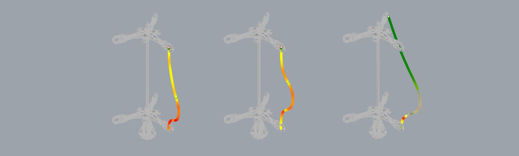
Green represents areas that are not sufficient in opening the ribs
Red represents areas that have excessive curvature to produce the required opening
RED
A1 A4 A7 A2 A5 A8 A3 A6 A9 RED
RED
RED YELLOW GREEN RED YELLOW GREEN RED
RED YELLOW GREEN RED YELLOW GREEN RED YELLOW GREEN 42.9 2.2 2.4 58.1 8.8 0.4 4.3 2.4 4.2 53.9 5.2 8.4 37.8 35.8 42.9 21.1 7.2 58 3.2 92.6 89.2 4.1 55.4 45.6 74.6 90.4 27.8
YELLOW GREEN
YELLOW GREEN
YELLOW GREEN
YELLOW GREEN
Figure 83 Authors image. Curvature analysis
84
Figure 84: Authors image. Curvature analysis
ASSEMBLY OF COMPONENTS
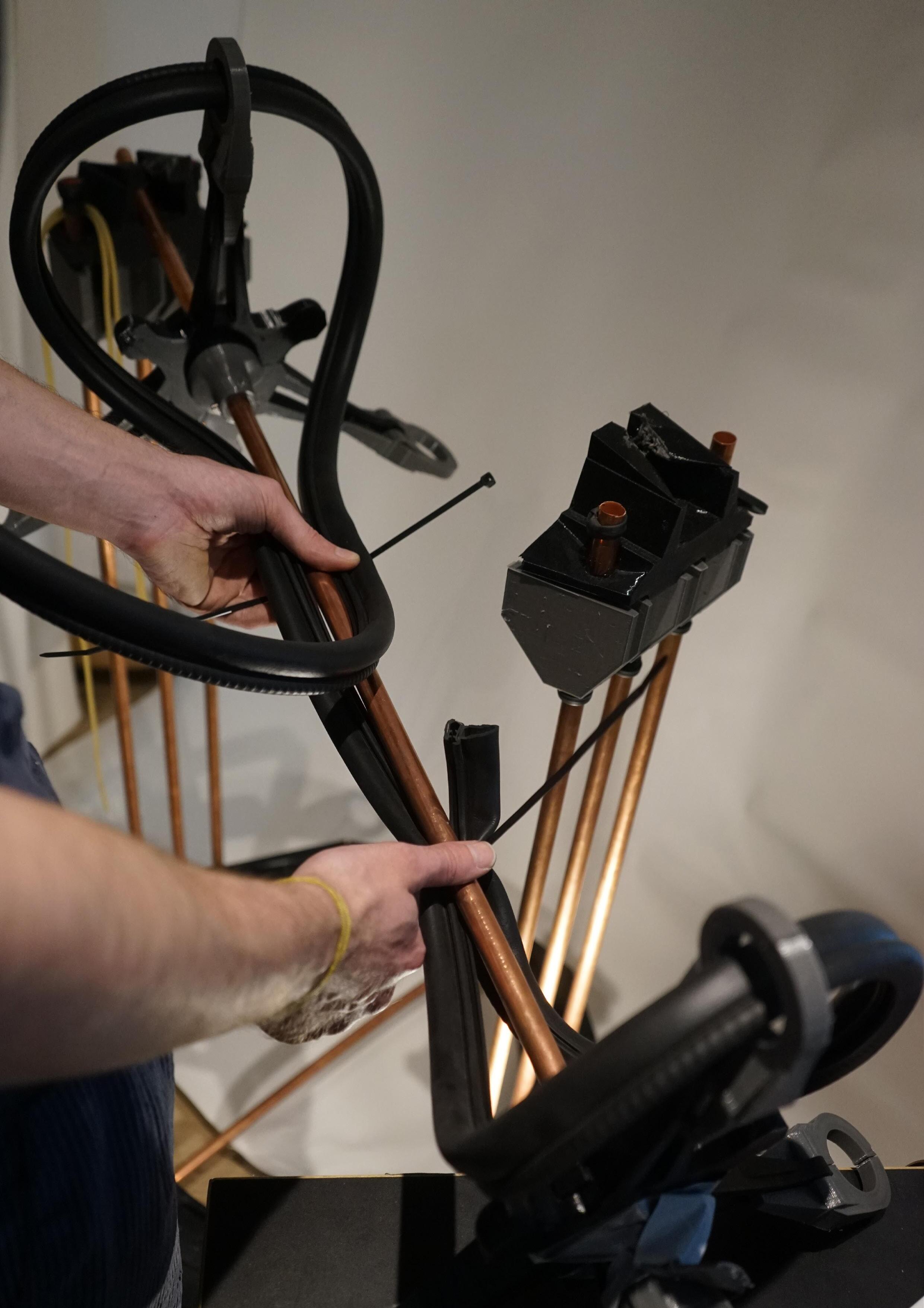
Once the optimised shape was determined, the pneumatic system used in triggering the deformation of the rib is implemented through first securing the hollow rubber rib to the end effector, holding it in place throughout the process of the robotic filament dispensation (Figure 85).
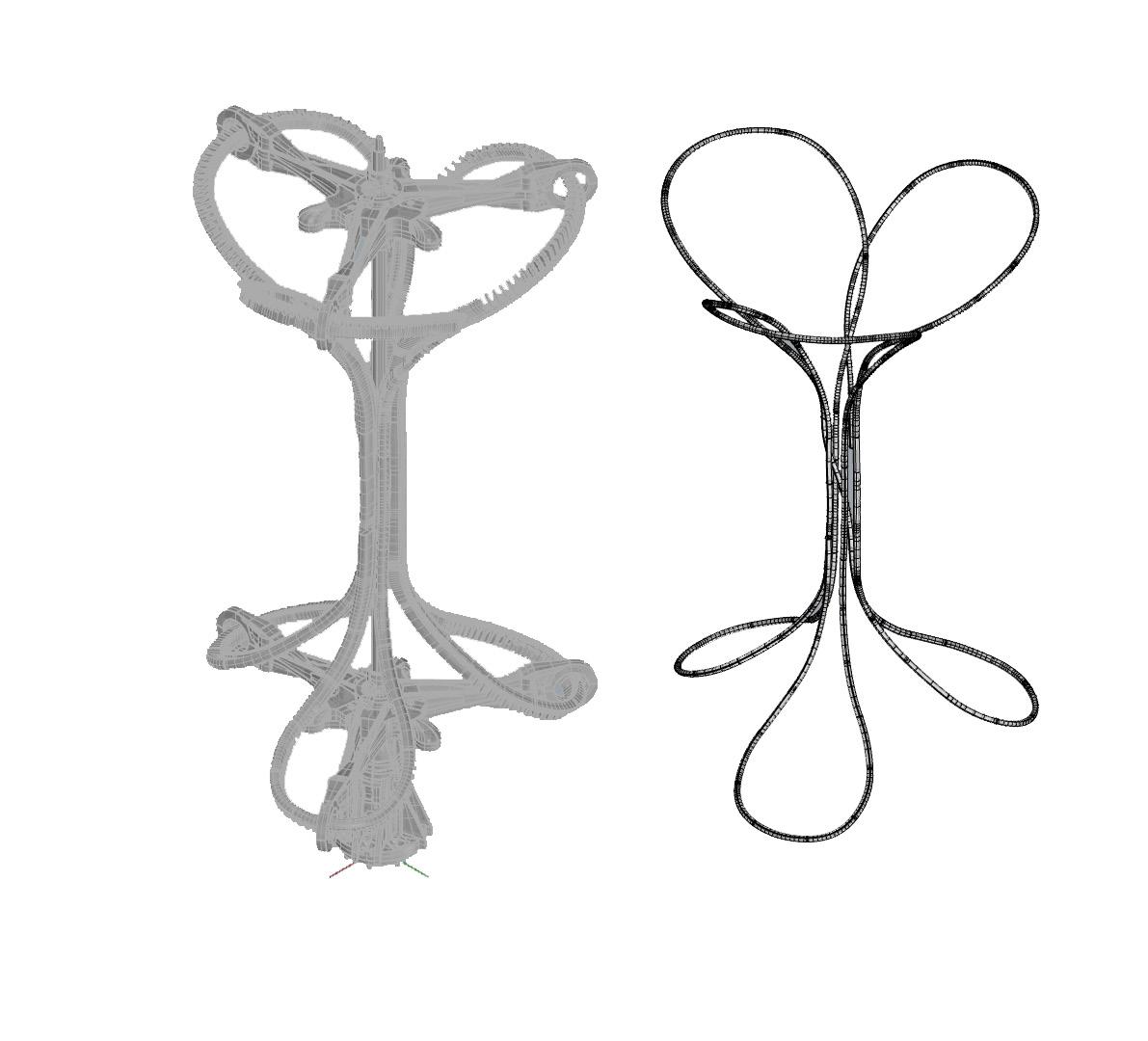
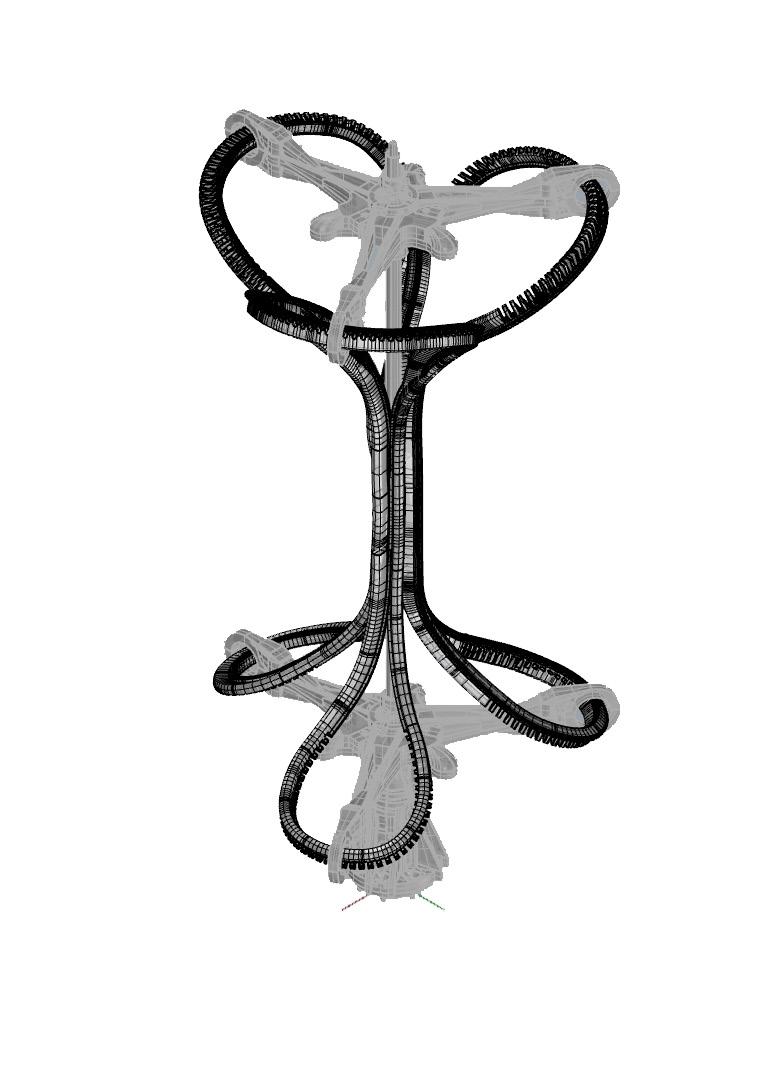
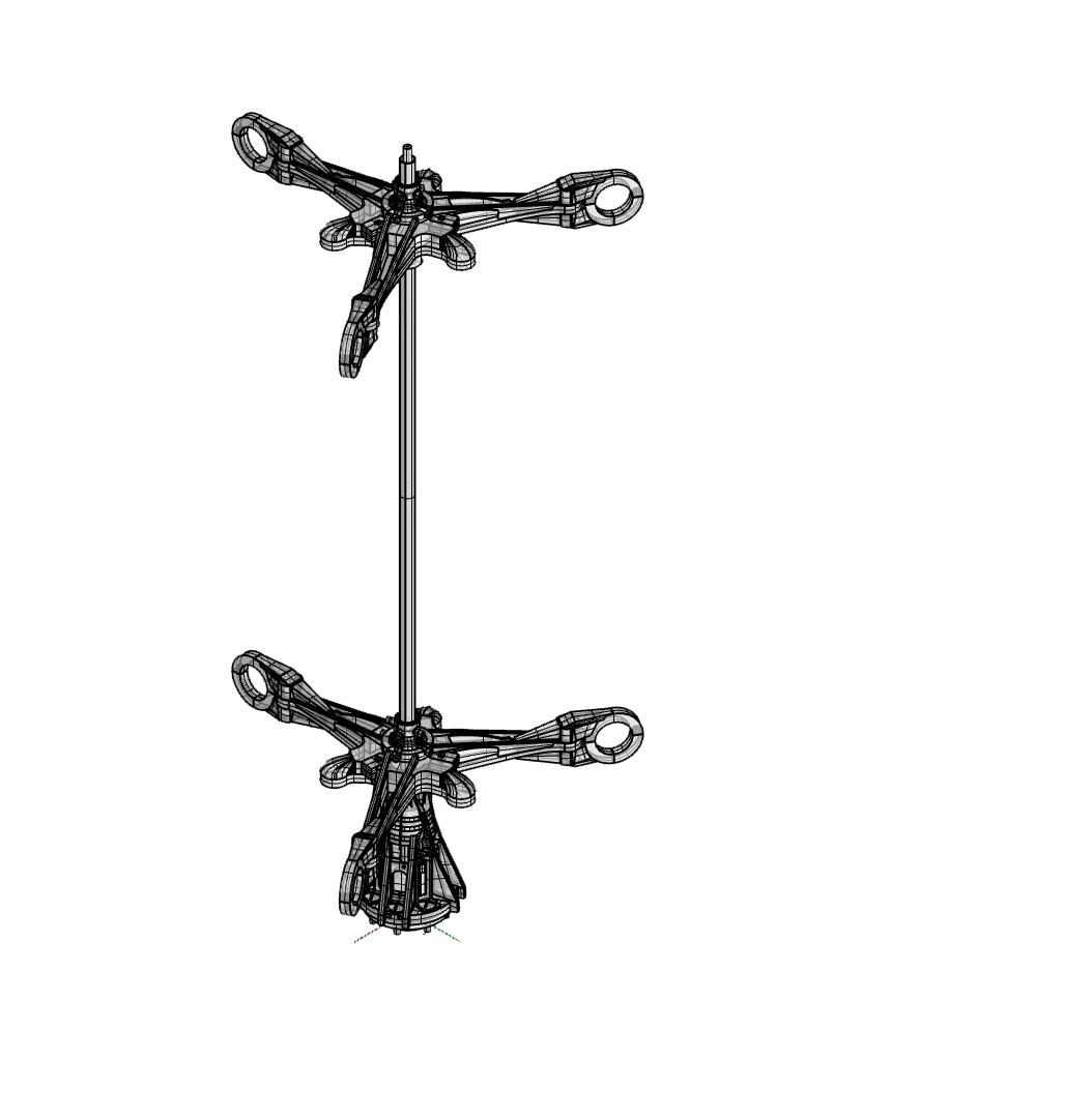
Following this, rubber balloons and air pipes are inserted within the hollow rubber rib to subsequently drive the pneumatic deformation post filament dispensation. This acts as the core differentiation of previous research conducted in robotic filament dispensation.
END EFFECTOR
RIBS AIR PIPES
RUBBER BALLOON
1 3 2 4 4.5 86 Figure 85
Figure 86
Authors image. Assembly of end effector and jig
Authors image. Assembly of end effector and jig
GA DESIGN
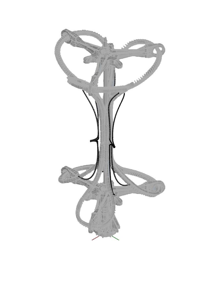
In order to determine a tool path within the limitation of the designed rib, a Genetic algorithm(GA) was used to determine a range of possible iterations within a selected constrained set of parameters tailored to the material performance of the design.
Genetic algorithms (GA) are popular metaheuristics and are used to determine the optimas within a generative design methodology, hence is suited in helping determine a pattern for the proposed prototype in the context of a potentially optimised framework.
The
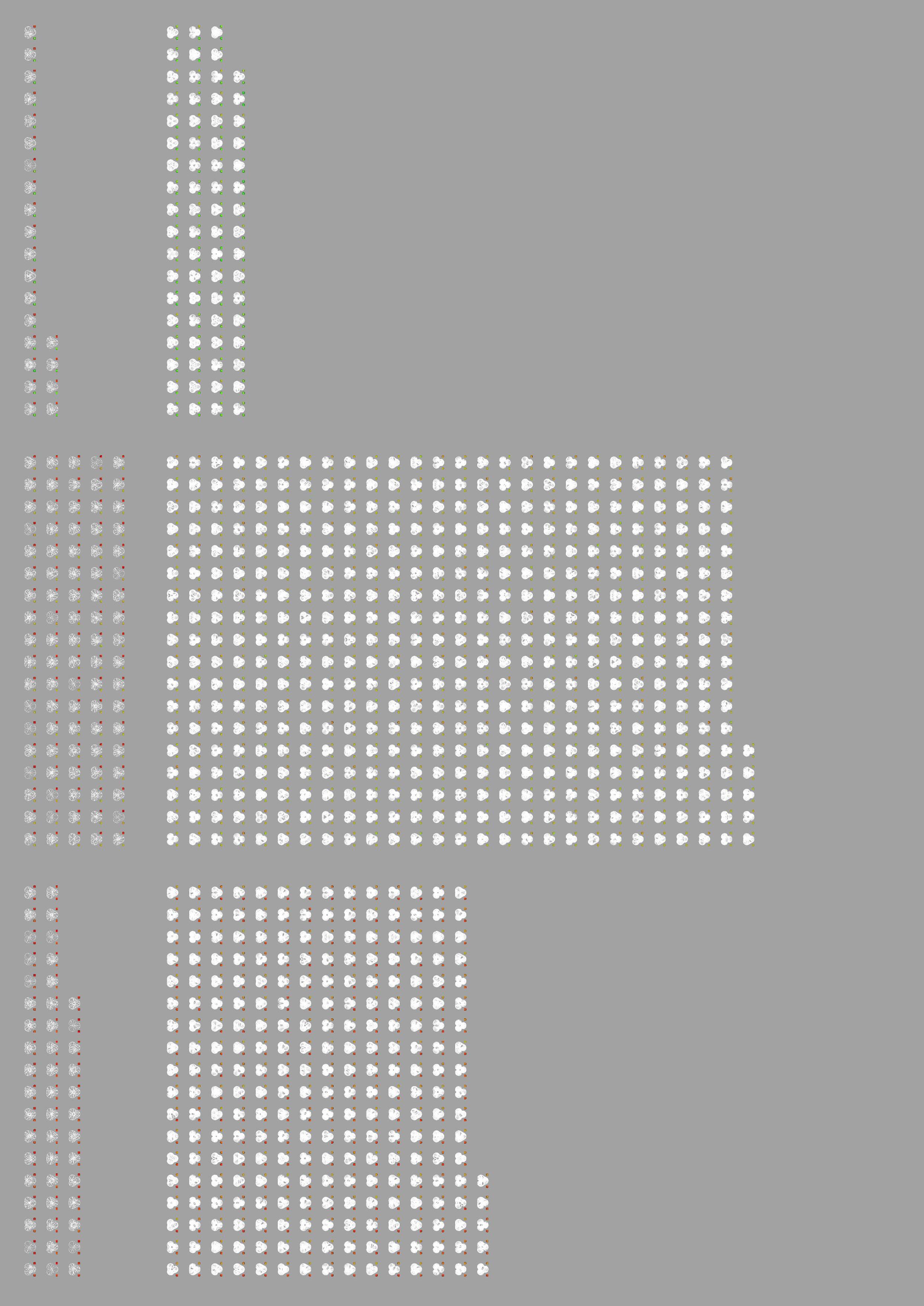
Once simulated we are given a defined amount of iterations tailored to testing the variations of the selected parameters, which in this case were defined as length between anchor points and criss-crossing of fibres for sturdiness. The colour either side of the iteration displays the quantified success of the attempt of optimising that parameter. Green-green, being optimal, red-red being low quality, and a variation signifying an uneven completion of the parameters.
The use of this tool allows for the selection of a range of ‘suitable‘ candidates that would work as tool paths.
4.6
OPTIMISED ITERATIONS LOW QUALITY ITERATIONS
selected GA applied within the design was developed by Tony Le at the Bartlett school of Architecture, whose particular GA was designed within VFX software HoudiniFX.
Figure 87: Image produced by Tony Le. GA iteration on authors work, sample of produced iterations
Figure 88: Image produced by Tony Le. GA iteration on authors work, sample of produced iterations
88
Figure 89 Authors image. Screenshot of samples produced of authors work using Tony Le’s GA.(Next page)
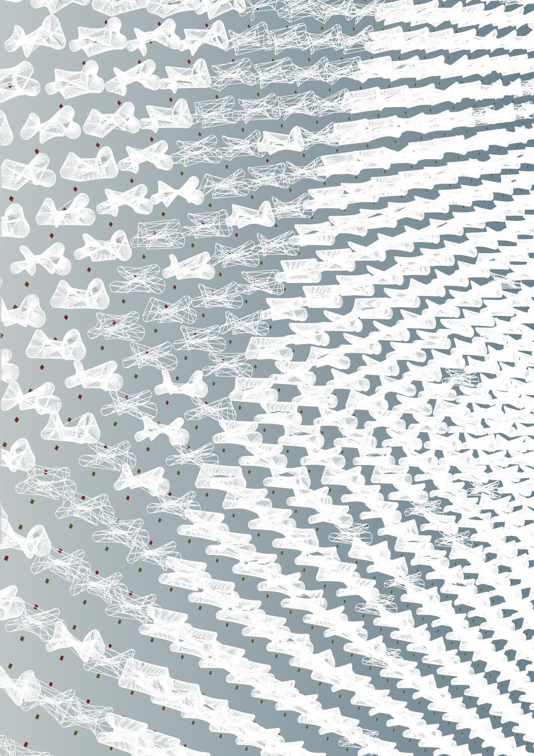
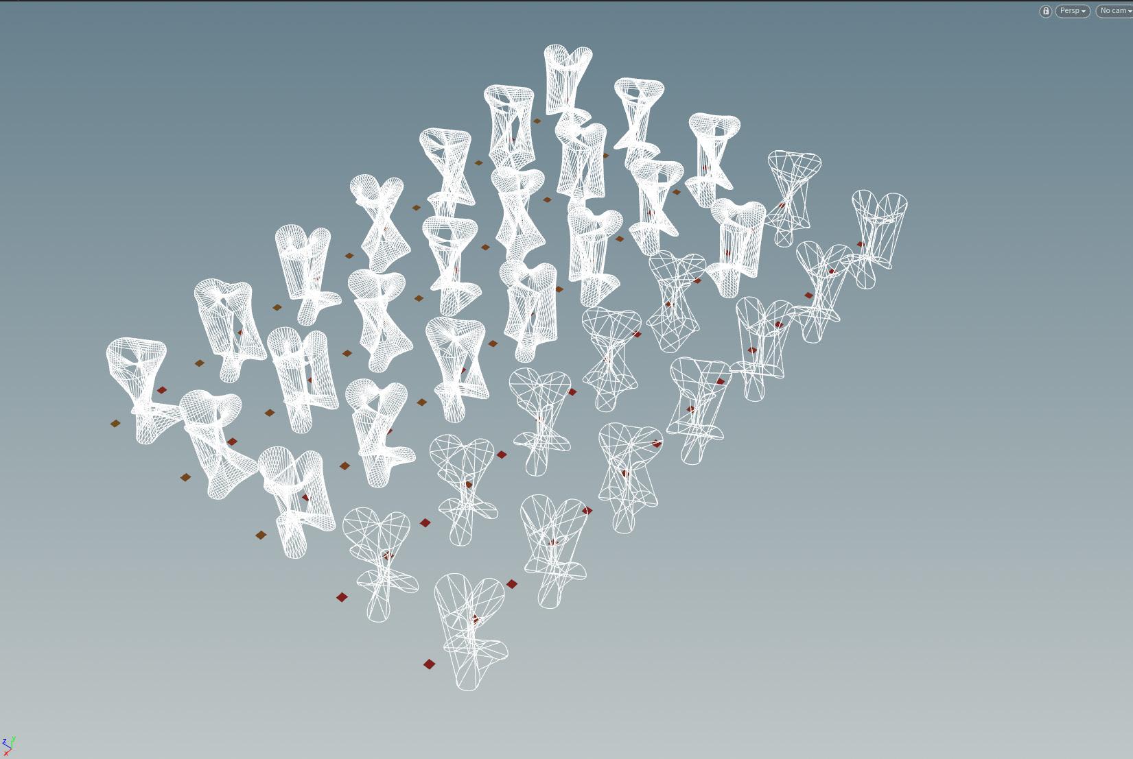
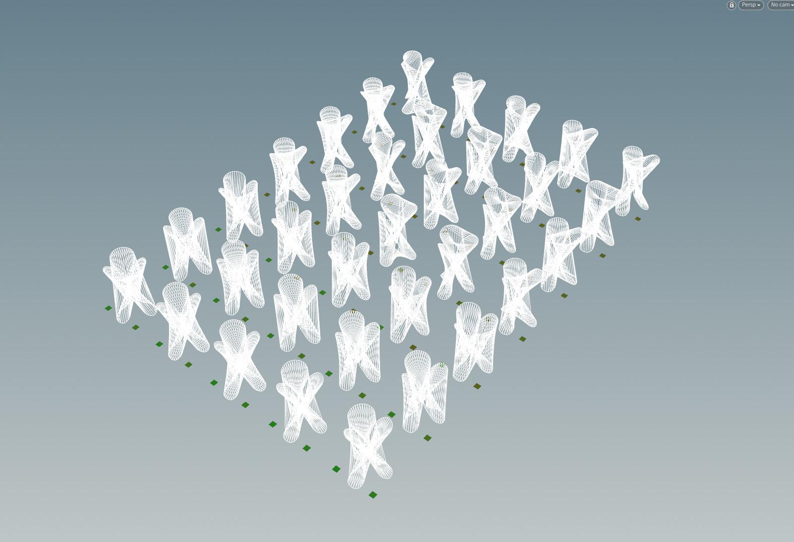 Figure 90 Authors image. Screenshot of samples produced of authors work using Tony Le’s GA. Unsuccessful pool
Figure 91 Authors image. Screenshot of samples produced of authors work using Tony Le’s GA. Successful pool
ROBOTIC SIMULATION
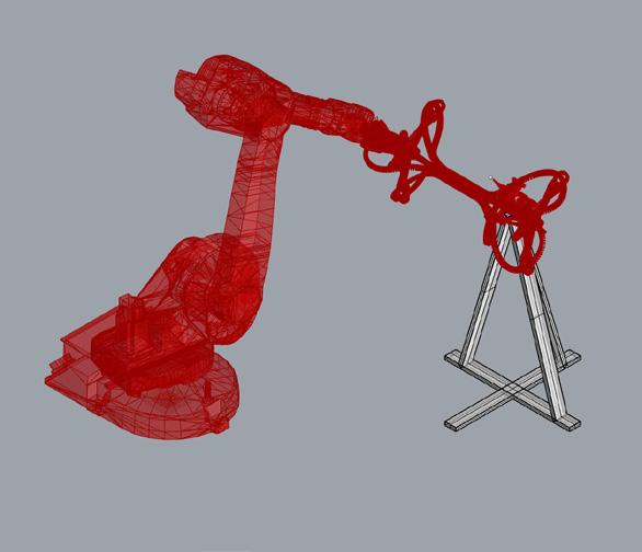
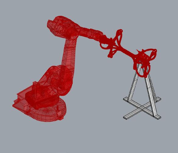
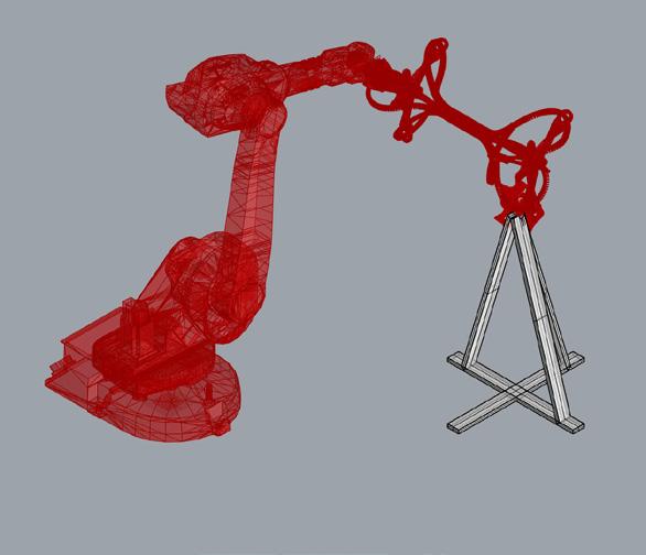
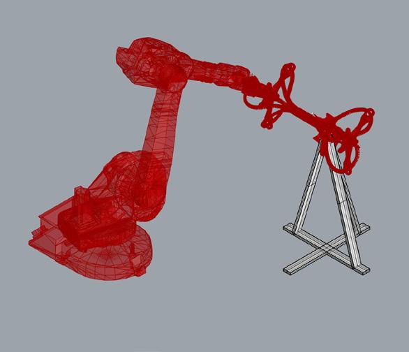
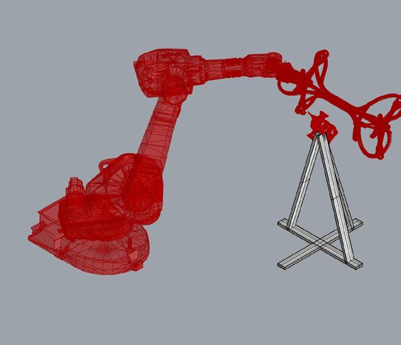
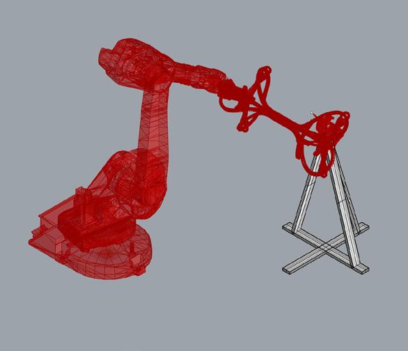
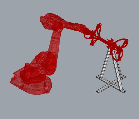
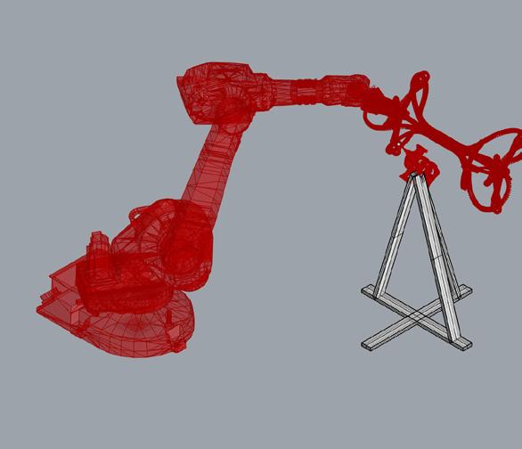
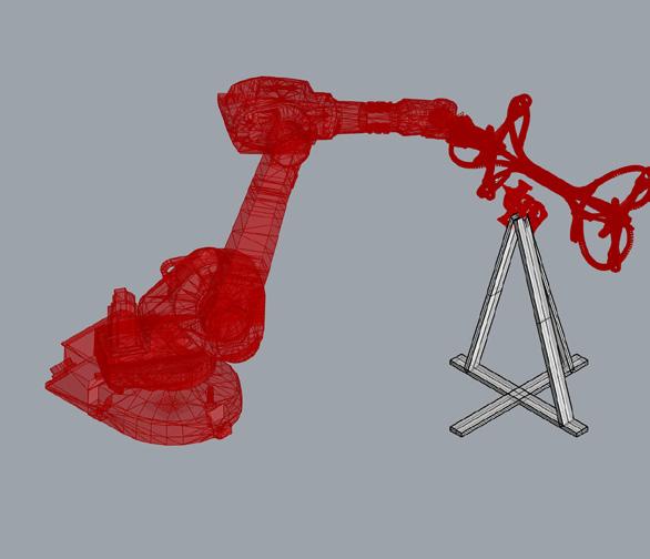
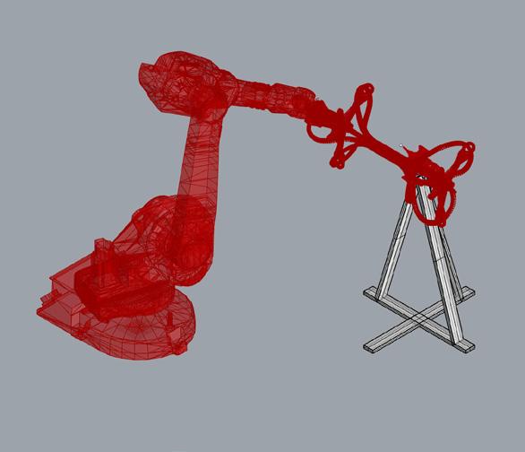
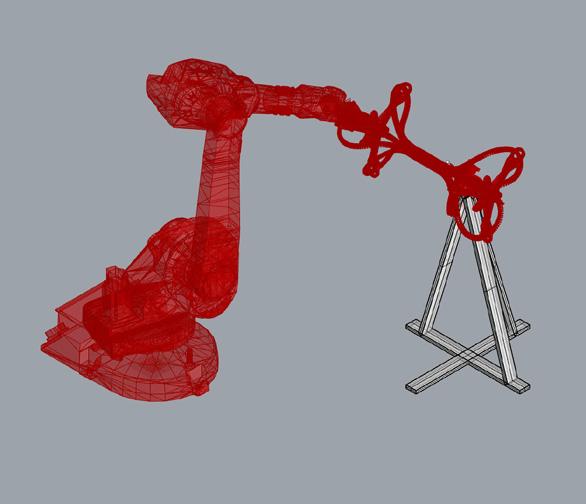
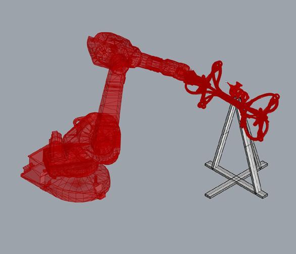
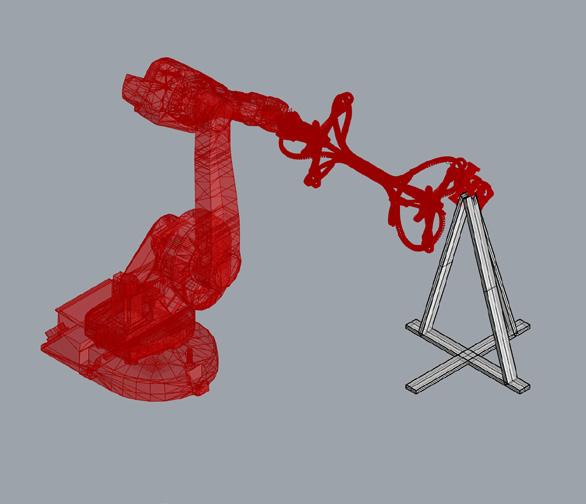
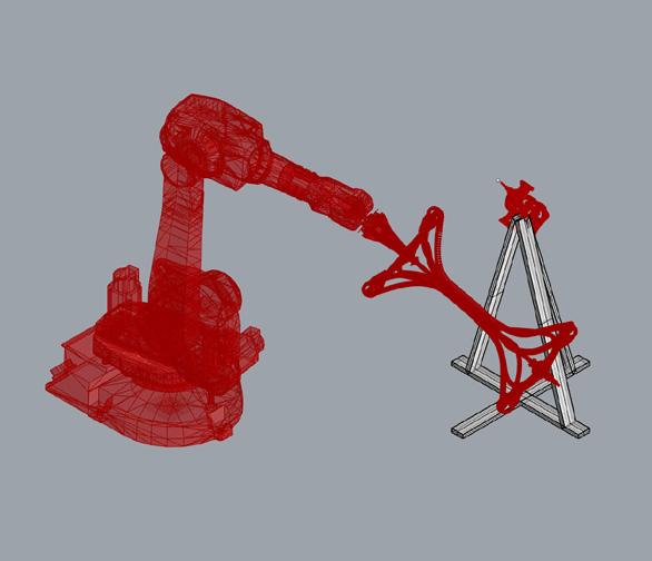
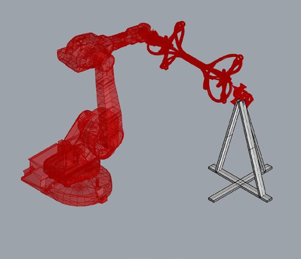
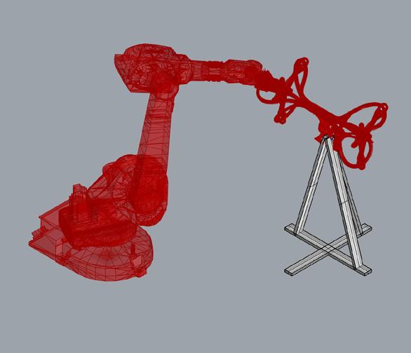
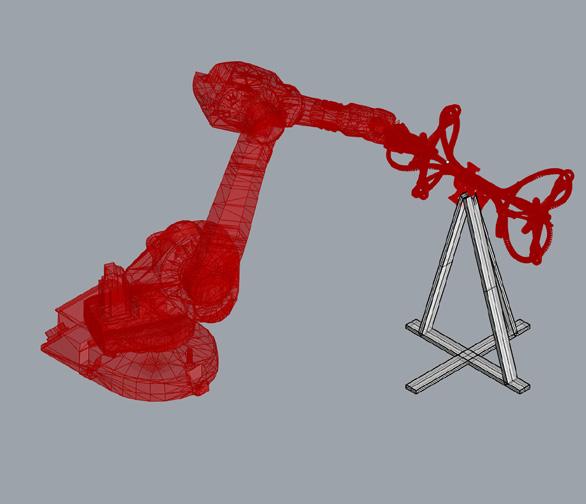
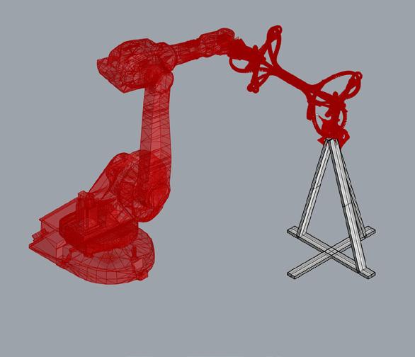
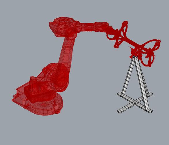
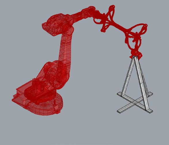
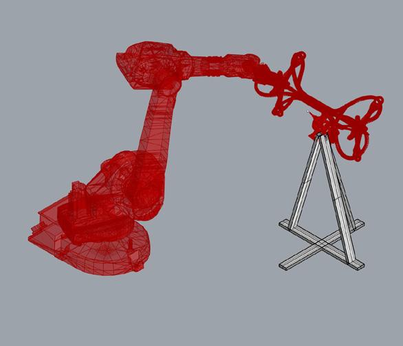
Once the path determined, the end effector geometry and the tool path are imputed into the developed grasshopper script. Each anchor point along the rib is targeted in the sequence of the developed GA tool, followed by a 120o rotation of the Arduino controlled stepper motor to ensure a constant ‘wrapping‘ of the prototype.
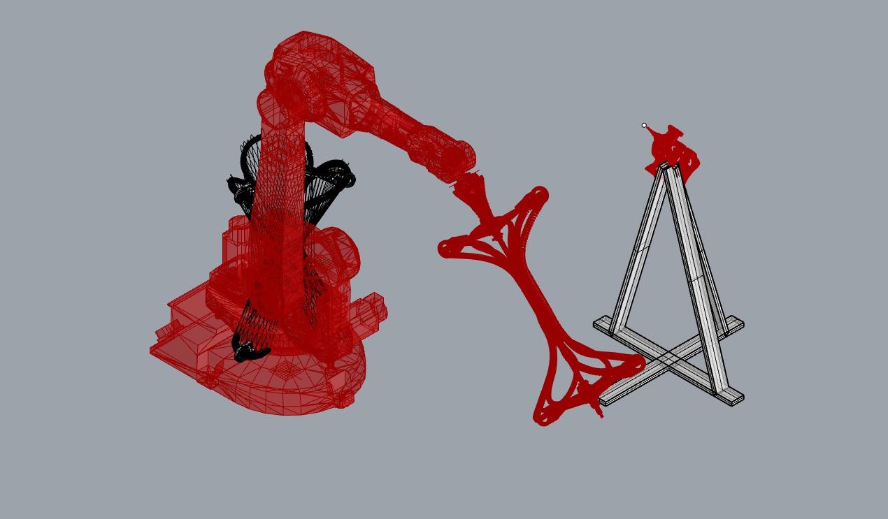
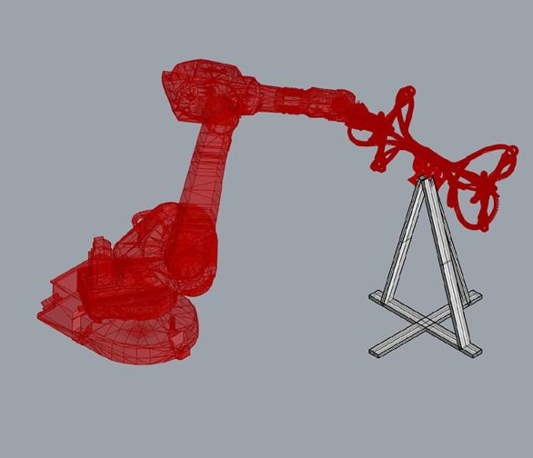
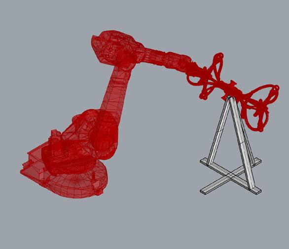
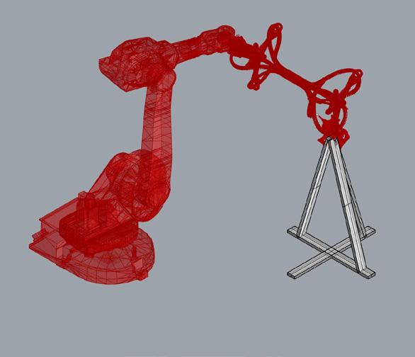
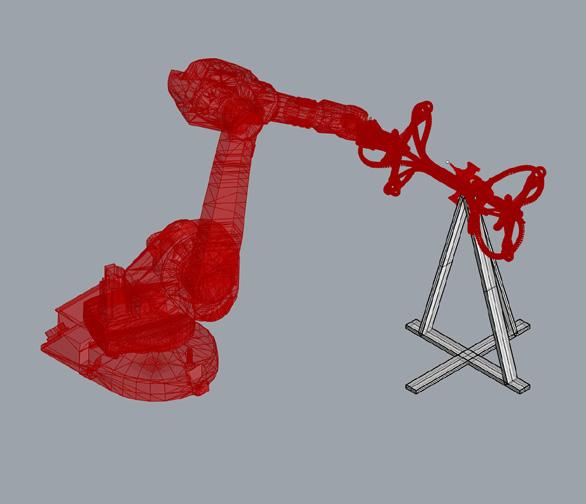
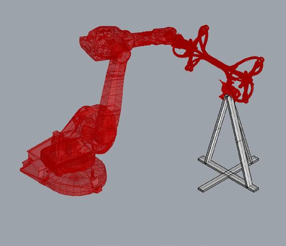
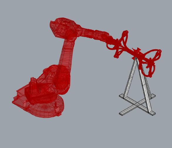
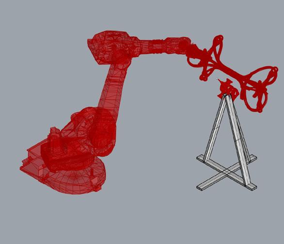
4.7
Figure 93 Authors image. Developed grasshopper script
Figure 94: Authors image. Sequences of targets undertaken by the robot
Figure 92 Authors image. Home position
92
Due to not being able to access the workshop due to the COVID 19 pandemic, the principal was tested manually by hand to ensure the filament secured as anticipated in the open rib incisions. The test was only performed with 3m of rubber thread due to the limited availability of cut material, however the outcome showed that as long as the criss cross pattern was maintained, i.e.. always traveling along the longest path between anchor points, the rib was able to securely hold the filament in place for the duration of the filament distribution process.
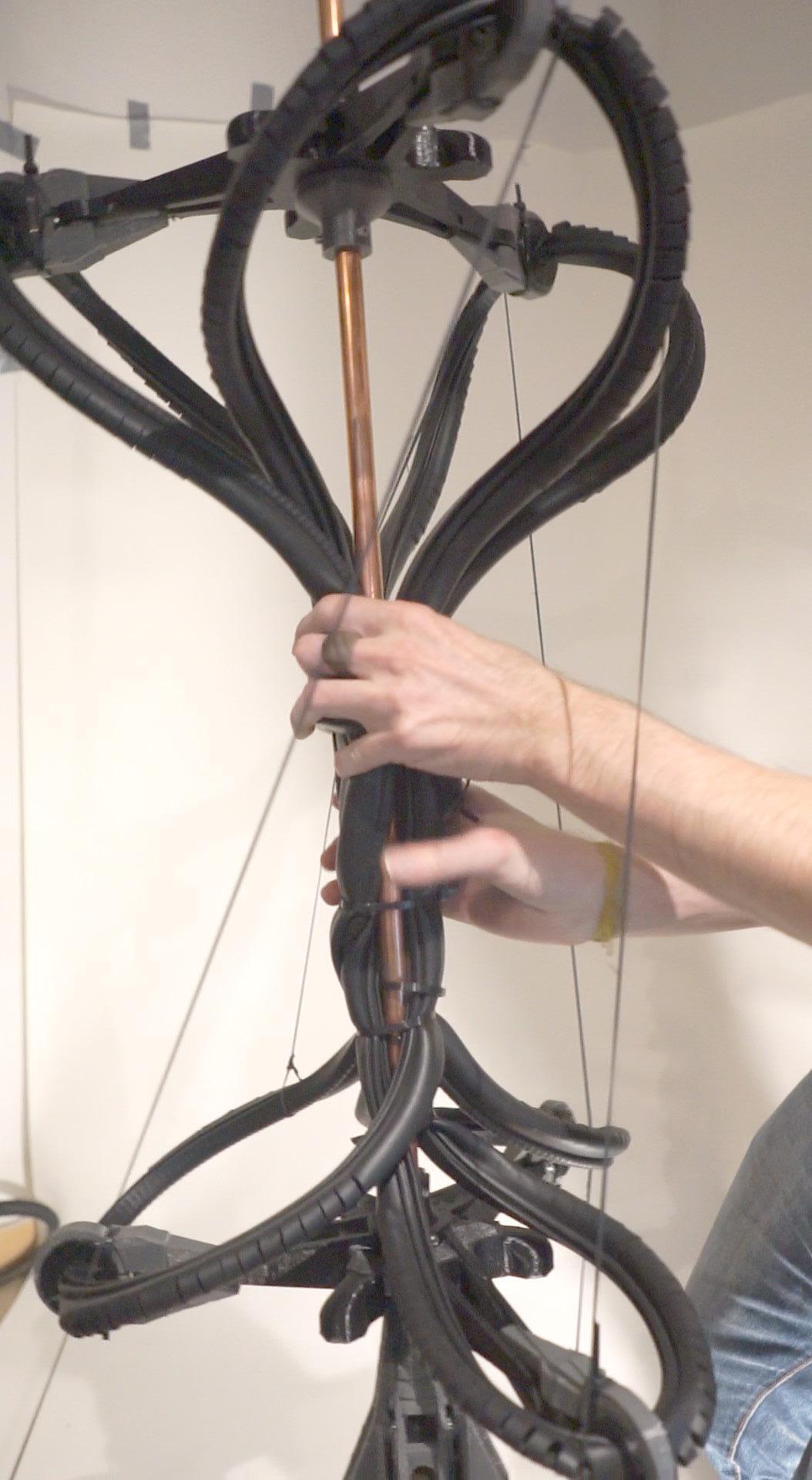
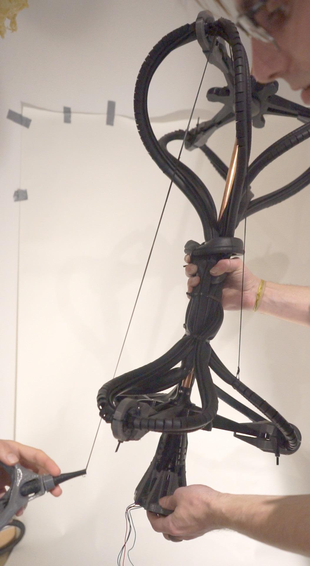
Furthermore to visualise the gradual formation of the path, the 3D geometry of the jig and curve were simulated in Houdini FX, carving the path of the geometry.
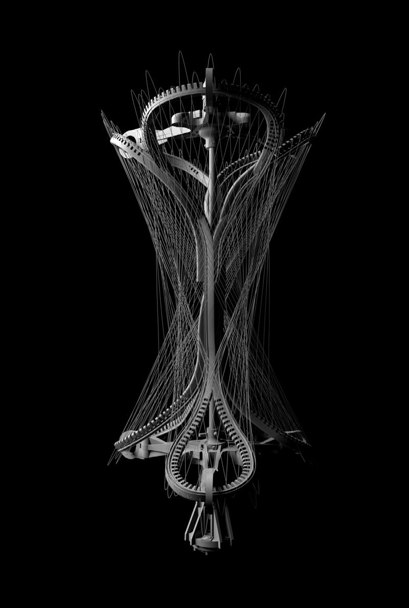
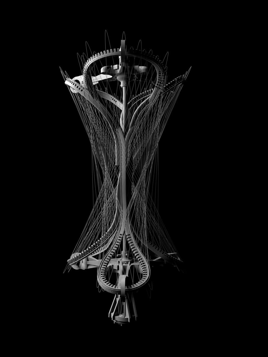
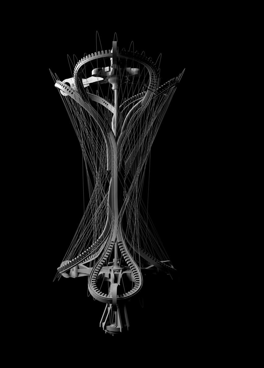
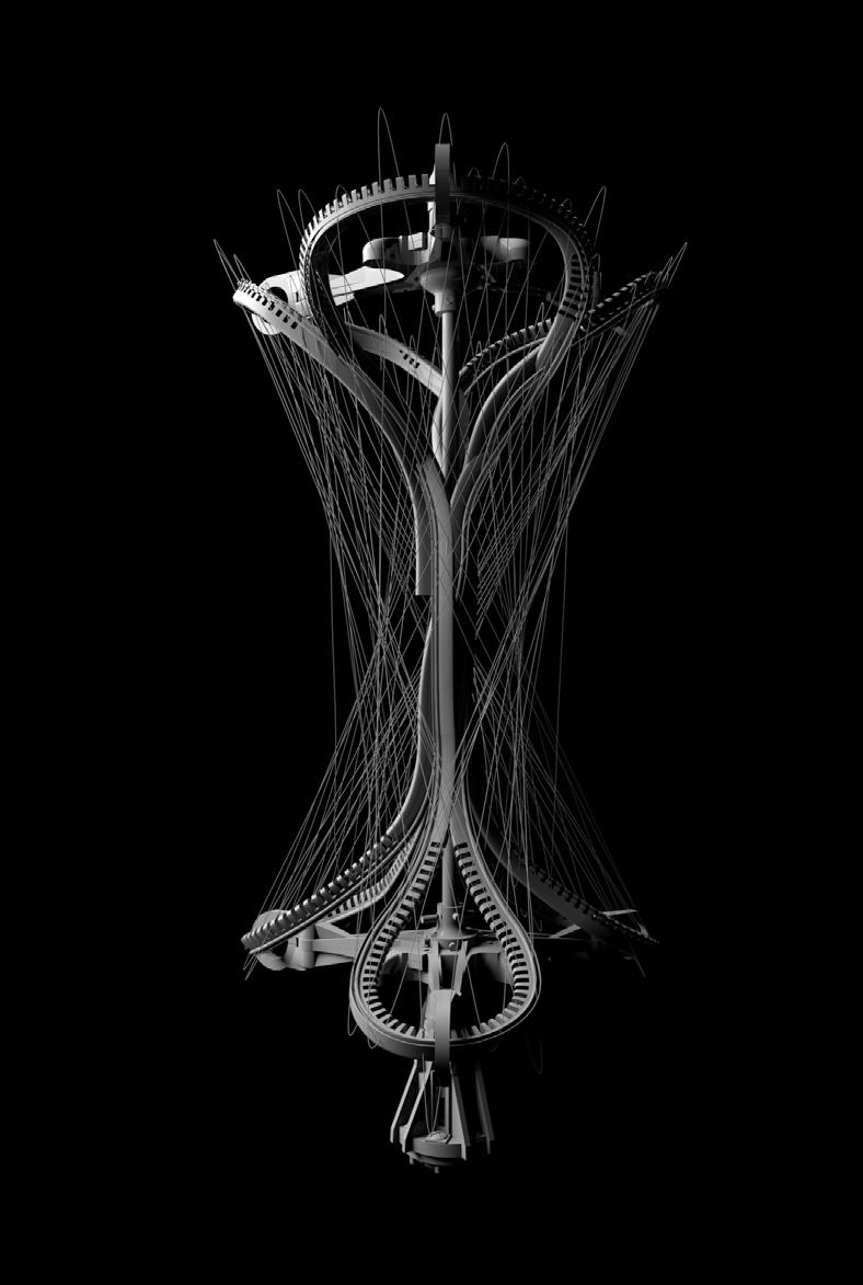
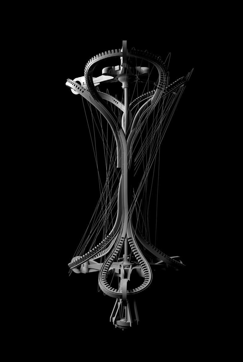
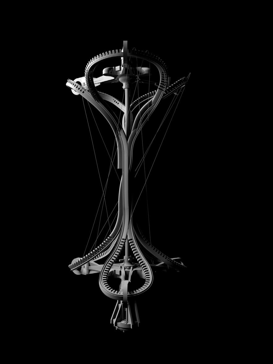
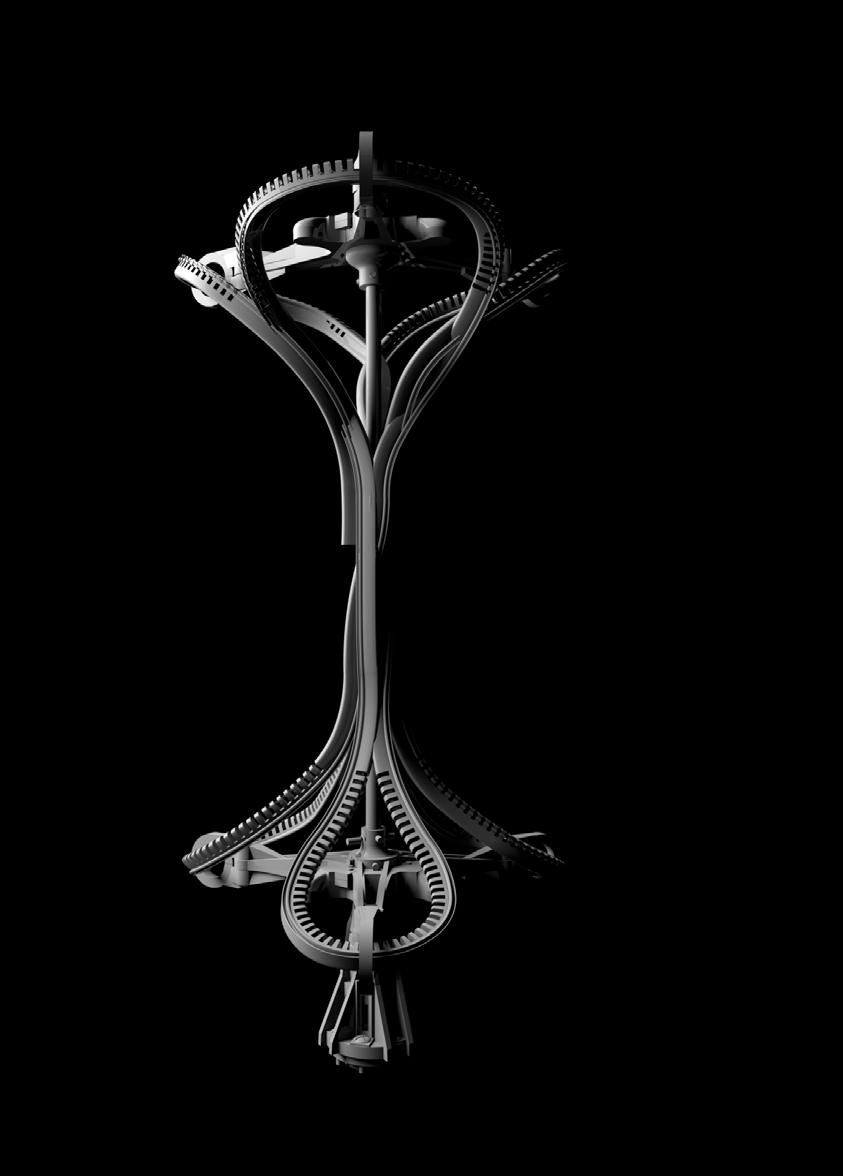 Figure10: Authors image. Filament dispenser annotation
Figure 95 Authors image. Physical prototype, testing or filament retention within slits
94
Figure 96 Authors image. Sequence of filigree dispensation
POST REMOVAL FORM
Once the automated woven sequence completed, the rubber rib and filament are to be removed from the end effector via un-threading the steel rod holding the assembly together(Figure 97.b).
Following this, the prototype would now lack the support required to retain its shape and would either collapse or shrink vertically.
In order to establish a stabilised shape, the form is folded in on itself (Figure 97.d), whereby the deformable and elastic qualities of the rubber would allow the derived geometry to self support through essentially ‘knotting‘ itself through the positioned filament.
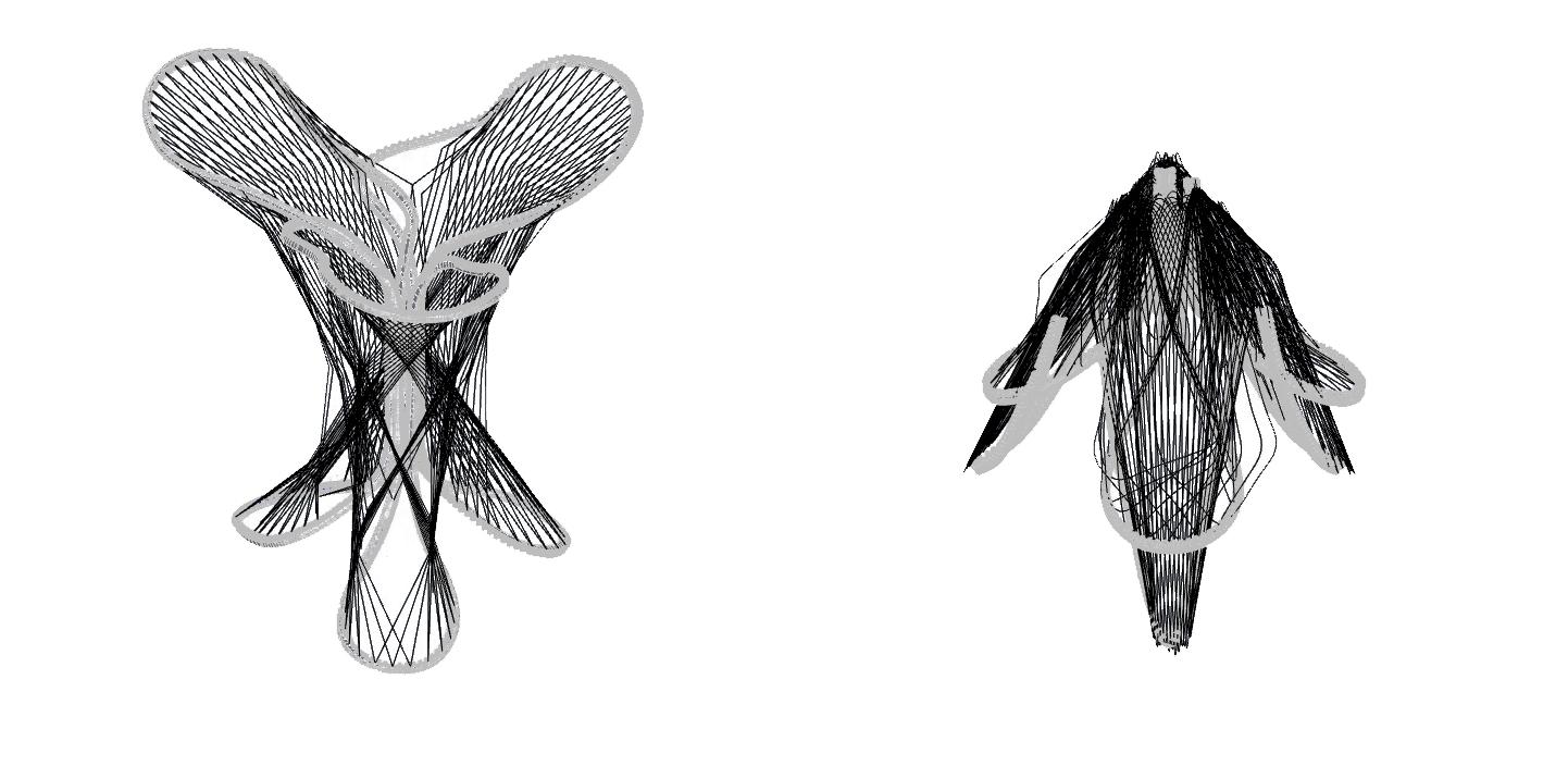
The rib holding the filament is considered to contain enough stiffness to be able to direct the filament into position, and if the filament was positioned with sufficient tension during the manufacturing process, the additional tension created through its insertion in the lower rib is speculated to lend itself in creating a tension based self supporting form.
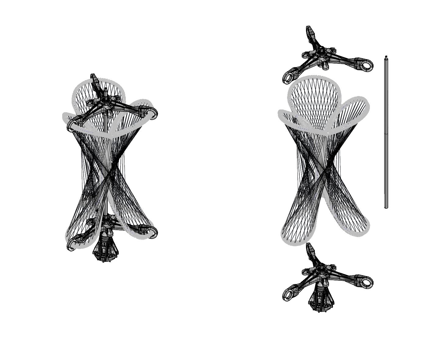 Rotate rib to lock the filament
Pull out top rib Pull filament to the side
B D A C
Remove end effector Pass top ribs through stretched out bottom rib
4.8 96 97
Figure 97: Authors image. Post deformation of prototype
The presented research proposes two main innovations in architectural building skins.
The first being that of a proposed temporal skin, containing an embedded time based decay. Through re-imagining the nature of the architectural skin as a multi layered, adaptive facade that can both respond to it environment in an dynamic and immediate scale through its elasticity as well as well as alter its form through its biodegradation. We open up a potential discourse on the practical applications of the alteration and allocation of purpose of space in response its surrounding conditions.
The second is the means and format of fabrication with this material. An optimised automated manufacturing methodology unique to the qualities of the material caters to a new technique of robotic fibre dispensation through the use of an adaptable ‘jig‘ that is deformed either manually or via pneumatics, post filament dispensation .
Unlike previous research in robotic filament dispensation, which ultimately aims to create a self supporting structure, the proposed research in this thesis caters to the flexible and elastic nature of natural rubber to create a multi layered pneumatically adaptive design.
Although the proposed scaled prototype does not reflect all the constraints associated with the up scaling of a prototype, the conducted research mirrors a series of strategies and issues of which the logic can be further developed for any up-scaled production using this particular material and manufacturing methodology.
From these encountered issues, we can speculate as to the potential means of furthering this research by more informed tests based on the information gathered within this thesis.
The first of these potential developments would be optimising the precision of the predicted lifespan of natural rubber whence exposed to UV light. Although the calculated lifespan is based on research conducted by leading material experts in the field rubber performance Rapra technologies. Discrepancies in the predictive calculations could be further diminished through long term external weathering tests, as opposed to the short term artificially simulated environments that don’t take into account additional unaccounted weathering factors that might further affect the rate of its degradation.
Furthermore a wider range of samples of commercially available natural rubber would be tested alongside customised compounds tailored to provide the desired rate of biodegradability, longevity and elasticity. However uniform testing of these materials would ideally be accompanied by the proportions, vulcanisation process and list of additives used in the manufacturing process. Unfortunately due to the commercial nature of the products, most manufacturers are reluctant to divulge this information.
Hence ideally custom blends would be manufactured and tested in regards to the particular desired outcome of the materials biodegradability, fire retardancy and elasticity whilst retaining the stability provided through its vulcanisation. However this process would most likely require the collaboration of an expert in the field of natural rubber compound mixing and vulcanisations processes and therefore require a wider scope of collaboration beyond this thesis.
The scale and format of the rubber used should also be further considered. Current rubber sheets obtained from retailers tend to be distributed in 1.4m by 10m rolls, determined by the size of the machine used in calendering the sheets. Ideally any large scale customised balloon driving the pneumatics of the fibres would therefore comply to the listed dimensions to avoid costly development of bespoke machines. As per the development of the fibre stands, it is assumed that an extruded format would be most suitable and could be obtained in long enough rolls to be used continually if the manufacturer was contacted directly, as most retailed natural rubber tubing tends to have a restricted length suited to broader commercial application.
Additionally, analogue tests conducted throughout this thesis using synthetic rubber (which was used in the testing of the ribs due to its availability in tubular form) would ideally be replicated using natural rubber . Although the ribs are only needed for their flexibility which can be similarly compared to that of natural rubber, any future proposal would require the bespoke fabrication of tailored profiles so as to cater to the full biodegradable qualities of natural rubber.
5.0 DISCUSSION
98 99
As per the development of the automated manufacturing methodology, the credibility of the developed logic would have benefited from a recursive feedback loop of physically testing the developed paths on the Universal robot arm (UR 10). However restricted access to workshop facilities during the COVID 19 pandemic have made this endeavour infeasible.
Although the scripted digital simulations do provide a level of comprehension on the proposed behaviour of the system, they cannot compensate for unanticipated performance issues that would have been uncovered in physical prototyping
Anticipated problems, particular to the fabrication sequence would have consisted of the following.
Consistent accuracy in the placement of cuts in the ribs. Unlike the manual (and imprecise) method used in cutting slits into ribs in the developed prototype. A workable prototype would require the rib pattern to either have been incorporated in the casting of a natural rubber rib, or a bespoke cutting device would be required to consistently cut a slit at the required placement.
Accurate placing and positioning of the ribs along the end effector within a 0.5mm precision radius would ensure that the correct anchor point was always targeted with each pass of the robot arm.
The flexibility of the material would also cause gradual deformation of the rib, meaning the deformation would have to be tested priorly and implemented within the designed tool path.
Areas of high stress along the rubber strands would be susceptible to breakage, therefore the blend of rubber used would require a fairly high tensile strength. Multiple ‘batches‘ of strand paths would be used to avoid the dilemma of one fibre snapping resulting in the entire design failing.
Overall the reviewed performance of the material in regards to its particular properties and the automated sequence developed would have benefited from more in depth analysis. This would have been achieved through industry access to the materials production as well as in person access to the Universities workshop facilities.
Although the closure of the required facilities due to the COVID 19 pandemic has impacted the original intention of this thesis, which would have consisted of testing and developing the necessary feedback loop between the performance of the material and behaviour of the tool. The resulting adaptation to these conditions has enabled this thesis to explore alternate means of developing the design through the use of a GA driven tool path as well as exploring delocalised means of fabrication that would have otherwise not been considered.
As a result the undertaken research has transitioned into a documentation of a series of parameters to build off of for future work. Hence through a gathered understanding of the behaviour of the material, further research would encompass a wider range of interaction with the materials format beyond that of the filigree. Effectively exploring a combination of multiple manners of exploiting the materials characteristics to create and accentuate the ephemeral qualities of the material.
100 101
Natural rubbers capability of responding to environmental conditions on multiple time scales (long term biodegradable vs. its short term elasticity) synergies its ability to react as a truly adaptive organic material.
Through establishing an estimated time frame for the decay of an UV exposed natural rubber sheet at approximately 18 years before failure, a multi layered architectural skin is proposed as the optimum method of incorporating the material within an time based architectural proposal.
The documented physical and digital tests of the proposed prototype effectively highlighted the constraints and parameters within which the material would subsequently be manipulated.
The use and application of the robotic arm was investigated as a means by which to fabricate for a time dependant design, native to the deformable nature of the material as well as a means by which to produce consistent and accurate reproductions of a component.
In conclusion, this thesis has explored the performance of natural rubber in relation to time based decay as well as investigate the materials flexible and elastic qualities within a tailored automated manufacturing methodology.
6.0 CONCLUSION
102 103
BIBLIOGRAPHY
1 Shropfer T, Carpenter J. Material Design: Informing Architecture by materiality. Basel: Birkhauser GmbH; 2011. p.120
2 Blank S. An introduction to plastics and rubbers in collections. Studies in Conservation. 1990; 35(2): 53-63.
3 Lambert S, Sinclair JC, Bradely LE, Boxall ABA. Effects of environmental conditions on latex degradation in aquatic systems. 2013; 447: 225-234.
4 Mathes KN. A brief history of development in electrical insulation. Boston, MA: IEE; 1991 .p.3
5 Earthship Biotecture. 40 year research and development of self sufficient housing made from recycled materials[Internet]. [Accessed December 2020]; Available from: https://www. earthshipglobal.com/building-with-tires
6 Build Abroad. The rise of tire homes and earth ships [Internet]. [Accessed 5 December 2020]; Available from: https://buildabroad.org/2016/12/19/tire-homes/
7 Electronics cooling. The thermal conductivity of rubbers/elastomers[Internet]. 1, November, 2001. [Accessed March 2021]; Available from: https://www.electronics-cooling. com/2001/11/the-thermal-conductivity-of-rubbers-elastomers/.
8 Build for less. A quick quid to U values [Internet]. 16 March 2020. [ Accessed 9 march 2021]; Available from: https://build4less.co.uk/blogs/guides-and-news/a-quick-guide-to-u-values
9 Home Logic. External wall insulation U values [Internet]. 27 November 2019. [ Accessed 9 march 2021]; Available from: https://www.homelogic.co.uk/external-wall-insulation-u-values#:~:text=The%20Average%20Wall%20U%20Value&text=Cavity%20wall%20(no%20insulation)%201.5,Insulated%20wall%200.18%20W%2Fm%C2%B2K59-
10 Designing buildings. U-Values [Internet]. 18 March 2021. . [ Accessed 9 march 2021]; Available from: https://www.designingbuildings.co.uk/wiki/Uvalues#:~:text=External%20 wall%3A%200.18%20W%2F(,%3A%201.4%20W%2F(m%C2%B2K).
11 Loadman J. Tears of the Tree: The story of rubber-A modern marvel. New York: oxford University Press; 2005.
12 Samsuri A. Strength and durability of natural rubber and chemically modified natural rubber. In: Thomas S, Chan C, Pothan LA, Joy J, Maria H, editors. Natural Rubber Materials: Composites and Nanocomposites. Volume 2. Cambridge: Royal Society of Chemsitry; 2014. p. 136-180.
13 Stewart B. How Building Learn: what happens after. Viking Press; 1994.
14 The Economist. Why Japanese houses have such limited lifespans[Internet]. March 15 2018. [ Accessed April 2021]; Available from: https://www.economist.com/finance-and-economics/2018/03/15/why-japanese-houses-have-such-limited-lifespans
15 The Atlantic. The mystery as to why Japanese people are having so few babies [Internet]. July 20, 2017 [ Accessed April 2021]; Available from: https://www.theatlantic.com/business/ archive/2017/07/japan-mystery-low-birth-rate/534291/
16 NPR. Japan’s population is in rapid decline [Internet]. 21 December 2018. [ Accessed April 2021]; Available from: https://www.npr.org/2018/12/21/679103541/japans-population-is-in-rapid-decline?t=1619550480626
17 Chen D, Hu M, Huang C, Zhang R. Preparation and Properties of Natural Rubber Composites and Nanocomposites. In: Thomas S, Chan C, Pothan LA, Joy J, Maria H, editors. Natural Rubber Materials:
Composites and Nanocomposites. Volume 2. Cambridge: Royal Society of Chemsitry; 2014. p. 112-135.
18 Nair AB, Joseph R. Eco-friendly bio composites using natural rubber(NR) matrices and natural fibre reinforcements. In: Kohjiya S, Ikeda Y, editors. Chemistry, manufacture and applications of natural rubber. Woodhead Publishing Limited; 2014. p. 249-
19 Puskas J, Chiang K, Barkakaty B. Natural rubber(NR) biosynthesis: perspectives from polymer chemistry. In: Kohjiya S, Ikeda Y, editors. Chemistry, manufacture and applications of natural rubber. Woodhead Publishing Limited; 2014. p. 30-67.
20 Eco world. Latex Vs rubber[internet]. 23 Febuary 2020. [Accessed 25th of December ]; Available from: https://ecoworldonline.com/latex-vs-rubber-is-it-the-same-thing/#:~:text=Rubber%20and%20latex%20are%20not,of%20a%20mature%20rubber%20tree.
21 Sakdapipanich JT, Rojruthai P. Natural Rubber: Biosynthesis, Structure, properties and application. In: Thomas S, Rajisha KR, Maria H, Chan C, Pothen L, editors. Natural Rubber Materials: Blends and IPNs. Cambridge: Royal Society of Chemistry; 2014. p. 28-52.
22 Namazie International. Technically specified or Block rubber (TSR)[internet]. 2019. [Accessed 24th of December 2020]; Available from: https://www.natural-rubber.com/products.php.
23 Ikeda Y. Understanding network control by vulcanization for sulfur cross-linked natural rubber (NR). In: Kohjiya S, Ikeda Y, editors. Chemistry, manufacture and applications of natural rubber. Woodhead Publishing Limited; 2014. p. 119-134.
24 Namazie International. Technically specified or Block rubber (TSR)[internet]. 2019. [Accessed 24th of December 2020]; Available from: https://www.natural-rubber.com/products.php.
25 Schidrowitz P, Dawson TR. History of the rubber industry: compiled under the auspices of the institution of the rubber industry. Cambridge: institute of the rubber industry by W. Heffer; 1952.
26 Furtado CRG, Leite MCAM. Life cycle analysis, ageing and degradation behavious of natural rubber based blends and IPNs. In: Thomas S, Rajisha KR, Maria H, Chan C, Pothen L, editors. Natural Rubber Materials: Blends and IPNs. Cambridge: Royal Society of Chemistry; 2014. p. 550-568.
27 Ismawi DHA, Harper JF, Ansarifar A. Influence of Flame retardant additives on the flammability behaviour of natural rubber(NR). 2008; 11(4): 223-236.
28 McKeen L. The effect of UV light and weather on plastic and elastomers. 4th ed. Oxford: William Andrew applied science publishers; 2019.
29 Smitthipong W, Thanawan S, Radabutra S, Vallat MF, Chollakup R, Tantatherdtam R, et al. Effect of non-rubber components on properties of sulphur crosslinked natural rubbers. 2013: 1-4.
30 Brown RP, Butler T. Natural ageing of rubber: changes in physical properties over 40 years. Shawsbury: Rapra technology limited; 2000.
31 Fenn J, Williams RS. Caring for plastics and rubbers[internet]. 16 July 2020.[Accessed 27 December 2020]; Available from: https://www.canada.ca/en/conservation-institute/services/ preventive-conservation/guidelines-collections/caring-plastics-rubbers.html#a2.
32 Nuttgens F, Tinkler Z. The conservation of rubberised textiles: two case histories. 2000; 24(1): 24-38.
7.0
104 105
LIST OF FIGURES
Figure 1 Dezeen. Belly of the beast is a hillside folly with a scruffy coat made from old tyres [Internet]. 17 April 2015. [Accessed March 2021]; Available from: https://www.dezeen. com/2015/04/17/belly-of-the-beast-hillside-folly-scruffy-coat-rubber-old-tyres-matt-ritani-declan-burn-brick-bay-contest-new-zealand/
Figure 2 Oregonlive. From the homefront: earth ships are designed for self-sufficiency[Internet]. 10 January 2019. [Accessed March 2021]; Available from: https://www.oregonlive.com/ hg/2012/10/from_the_home_front_earthships.html
Figure 3 Nicky abroad. Earthships and sound and festival [Internet] 20 June 2015. [Accessed March 2021]; Available from: https://nickyabroad.com/2015/06/20/earthship-and-sound-andlight-festival/
Figure 4 Diagram by author. Harry Hinton-Hard. 2021
Figure 5 Stewart B. How Building Learn: what happens after. Viking Press; 1994
Figure 6 Render of design studio project by author. Harry Hinton-Hard. 2021
Figure 7 Render of design studio project by author. Harry Hinton-Hard. 2021
Figure 8 Alamy. Sheets of natural rubber, Thailand [Internet]. 15 February 2011. [Accessed march 2021]; Available from: https://www.alamy.com/stock-photo-sheets-of-latex-natural-rubber-thailand-35088609.html?pv=1&stamp=2&imageid=AA439EB2-1B24-4BEF-946A
Figure 9 Diagram by author. Harry Hinton-Hard. 2021
Figure 10 Diagram by author. Harry Hinton-Hard. 2021
Figure 11 JSTOR. A delicate balance: Packing, handling, and installation of ephemeral works by Eva Hesse[Internet] 2008. [Accessed march 2021]; Available from: https://www.jstor.org/stable/27784621?seq=1
Figure 12 Brown RP, Butler T. Natural ageing of rubber: changes in physical properties over 40 years. Shawsbury: Rapra technology limited; 2000
Figure 13 Traced by author, based on: Brown RP, Butler T. Natural ageing of rubber: changes in physical properties over 40 years. Shawsbury: Rapra technology limited; 2000
Figure 14 Brown RP, Butler T, Hawley SW. Ageing of rubber: accelerated Weathering and Ozone test results. Shawsbury: Rapra technology limited; 2001
Figure 15 Brown RP, Butler T, Hawley SW. Ageing of rubber: accelerated Weathering and Ozone test results. Shawsbury: Rapra technology limited; 2001
Figure 16 Brown RP, Butler T, Hawley SW. Ageing of rubber: accelerated Weathering and Ozone test results. Shawsbury: Rapra technology limited; 2001
Figure 17 Comparison data sheet accumulated by author. Harry Hinton-Hard. 2021
Figure 18 Photograph by author. Harry Hinton-Hard. 2021
Figure 19 Comparison of test results accumulated by author. Harry Hinton-Hard. 2021
Figure 20 Photograph by author. Harry Hinton-Hard. 2021
Figure 21 Comparison of test results accumulated by author. Harry Hinton-Hard. 2021
Figure 22 Comparison of test results accumulated by author. Harry Hinton-Hard. 2021
Figure 23 Photograph by author. Harry Hinton-Hard. 2021
Figure 24 Photograph by author. Harry Hinton-Hard. 2021
Figure 25 Photograph of exo terra data sheet taken by by author. Harry Hinton-Hard. 2021
Figure 26 Comparison of test results accumulated by author. Harry Hinton-Hard. 2021
Figure 27 Comparison of test results accumulated by author. Harry Hinton-Hard. 2021
Figure 28 Photograph by author. Harry Hinton-Hard. 2021
Figure 29 Photograph by author. Harry Hinton-Hard. 2021
Figure 30 Photograph by author. Harry Hinton-Hard. 2021
Figure 31 Photograph by author. Harry Hinton-Hard. 2021
Figure 32 Leipziger messe. Textiles to composites: 3D moulding and automated fibre placement for flexible membranes[Internet] 2021 [Accessed march 2021] ; Available from: http://www. designersopen.de/Conference/Details-Vortraege/
Figure 33 Leipziger messe. Textiles to composites: 3D moulding and automated fibre placement for flexible membranes[Internet] 2021 [Accessed march 2021] ; Available from: http://www. designersopen.de/Conference/Details-Vortraege/
Figure 34 Diagram by author. Harry Hinton-Hard. 2021
Figure 35 Atelier Robotiq. Out of order hanglamp van atelier robotiq [Internet]. 2019 [Accessed December 2020] ; Available from: https://vimeo.com/304831824
Figure 36 Achimenges. ICD/ITKE research Pavillion 2013-2014 [Internet]. 2012. [Accessed March 2021]; Available from: http://www.achimmenges.net/?p=5561
Figure 37 Traced by author based on: Vasey L, Felbrich B, Menges A. Physically distributed muli-robot coordination and collaboration in construction.construction robotics. 2020; 4:3-18
Figure 38 Traced by author based on: Vasey L, Felbrich B, Menges A. Physically distributed muli-robot coordination and collaboration in construction.construction robotics. 2020; 4:3-18
Figure 39 Vasey L, Felbrich B, Menges A. Physically distributed muli-robot coordination and collaboration in construction.construction robotics. 2020; 4:3-18
Figure 40 Vasey L, Felbrich B, Menges A. Physically distributed muli-robot coordination and collaboration in construction.construction robotics. 2020; 4:3-18
Figure 41 Diagram by author. Harry Hinton-Hard. 2021
Figure 42 Diagram by author. Harry Hinton-Hard. 2021
Figure 43 Photograph by author. Harry Hinton-Hard. 2021
Figure 44 Diagram by author. Harry Hinton-Hard. 2021
Figure 45 Diagram by author. Harry Hinton-Hard. 2021
Figure 46 Photograph by author. Harry Hinton-Hard. 2021
Figure 47 Photograph by author. Harry Hinton-Hard. 2021
Figure 48 Diagram by author. Harry Hinton-Hard. 2021
Figure 49 Diagram by author. Harry Hinton-Hard. 2021
Figure 50 Photograph by author. Harry Hinton-Hard. 2021
Figure 51 Photograph by author. Harry Hinton-Hard. 2021
Figure 52 Photograph by author. Harry Hinton-Hard. 2021
Figure 53 Photograph by author. Harry Hinton-Hard. 2021
Figure 54 Screenshot of grasshopper script by author. Harry Hinton-Hard. 2021
Figure 55 Screenshot of grasshopper script by author. Harry Hinton-Hard. 2021
Figure 56 Diagram by author. Harry Hinton-Hard. 2021
Figure 57 Diagram by author. Harry Hinton-Hard. 2021
Figure 58 MIT media lab. Spatial flux: body and architecture in space [Internet]. 2018. [Accessed March 2021]; Available from: https://www.media.mit.edu/projects/spatial-flux/overview/
Figure 59 Belding L, Bayetkin B, Bayetejin H, Rothemund P, Verma M, Nemiroski A, et al. slit tubes for semisoft pneumatic actuators. Communication. 2018; 30:1-10
Figure 60 Photograph by author. Harry Hinton-Hard. 2021
Figure 61 Photograph by author. Harry Hinton-Hard. 2021
Figure 62 Photograph by author. Harry Hinton-Hard. 2021
Figure 63 Photograph by author. Harry Hinton-Hard. 2021
Figure 64 Photograph by author. Harry Hinton-Hard. 2021
Figure 65 Photograph by author. Harry Hinton-Hard. 2021
Figure 66 Photograph by author. Harry Hinton-Hard. 2021
Figure 67 Photograph by author. Harry Hinton-Hard. 2021
Figure 68 Photograph by author. Harry Hinton-Hard. 2021
Figure 69 Photograph by author. Harry Hinton-Hard. 2021
Figure 70 Photograph by author. Harry Hinton-Hard. 2021
Figure 71 Photograph by author. Harry Hinton-Hard. 2021
Figure 72 Photograph by author. Harry Hinton-Hard. 2021
Figure 73 Photograph by author. Harry Hinton-Hard. 2021
Figure 74 Photograph by author. Harry Hinton-Hard. 2021
Figure 75 Photograph by author. Harry Hinton-Hard. 2021
Figure 76 Photograph by author. Harry Hinton-Hard. 2021
Figure 77 Diagram by author. Harry Hinton-Hard. 2021
Figure 78 Photograph by author. Harry Hinton-Hard. 2021
Figure 79 Diagram by author. Harry Hinton-Hard. 2021
Figure 80 Photograph by author. Harry Hinton-Hard. 2021
Figure 81 Diagram by author. Harry Hinton-Hard. 2021
Figure 82 Photograph by author. Harry Hinton-Hard. 2021
108 109
