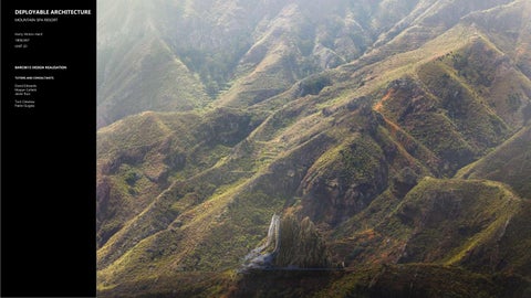
PROJECT AMBITION AND CONTEXT
The projects focuses on deriving a methodology of construction and design for a luxury hotel and spa resort in a remote and topographically challenging site.
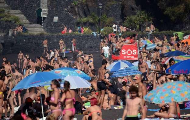
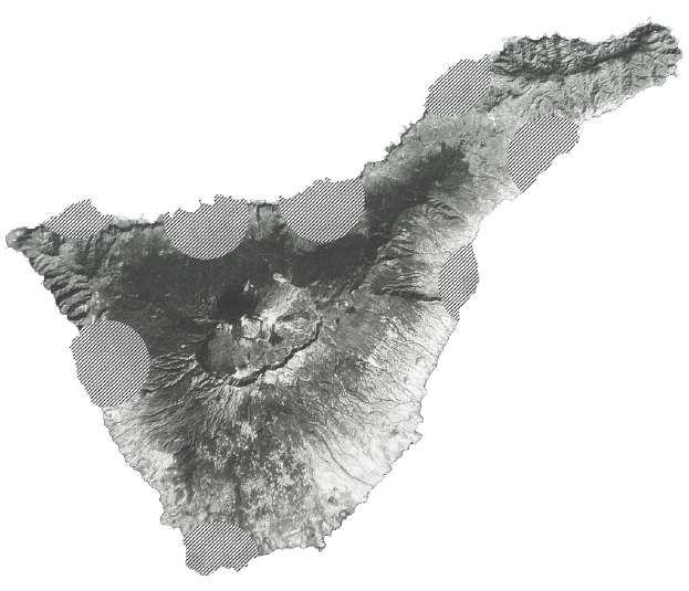
As of 2016, the government body of the island of Tenerife (Located in the Canary Islands) initiated a ‘rebranding’ proposal for tourism on the island due to concerns of a predicted decline in tourist activity as its beaches become overcrowded and oversaturated. To address this, the local government has proposed a new approach to tourism in Tenerife, focusing on a rebranding of the islands image as a ‘rural resort’. Through fewer but higher calibre of hotel builds spread throughout its mountainous terrain inland.
This project will act as a testing bed for a proposed build in one of these extreme mountain terrains. Key aspects that will be investigated will be the methods of construction required to fabricate a building in a challenging site and the buildings performance in this remote location.
Through an innovative approach of rendering this proposal self-sufficient and responsive to the local climate, experimental features such as an intelligent skin and a unique approach to adapting to and harnessing the sites unique topography have informed the projects ambition of creating a ‘reactive‘ design that is informed by its immediate context.
Tenerife and the Canary islands have experienced a massive surge in tourism over the past 5 years, with many foreign European countries tourists visiting the islands due to its year round temperate climate. Whereas previously 50 years ago the islands were remote and secluded tourist destinations they now host surges of tourists all year round. Tourists seeking the sunshine and beaches first began to visit the Canaries in large numbers in the 1960s. Canary Islands resides as one of Europeans most attractive tourist destinations due to its climate and scenery.
TENERIFE
The Canary Islands contains 257 kilometres of beaches. Although the small land mass of the islands, they each have very diverse landscapes, including beaches, cliffs, deserts, and woods. This diverse biosphere is extremely attractive to visiting tourist. Hosting four national parks and four biosphere reserves (Gran Canaria, Lanzarote, Fuerteventura and La Palma), and 140 other protected areas.
Tenerife being the largest and most visited island of the Canary Islands receives on average 5 million tourists each year, making it the most popular and overcrowded island of the Canary Islands.
Gran Canaria state located in Tenerife has nearly 50% of its territory declared an UNESCO Biosphere Reserve alongside a multitude of parks and protected landscapes.
Lanzarote is the most north-easterly region of Tenerife and has been designated as a UNESCO Biosphere Reserve. It has an arid volcanic landscape and there are about 300 volcanic cones on the island.

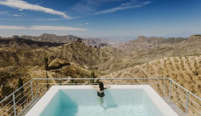
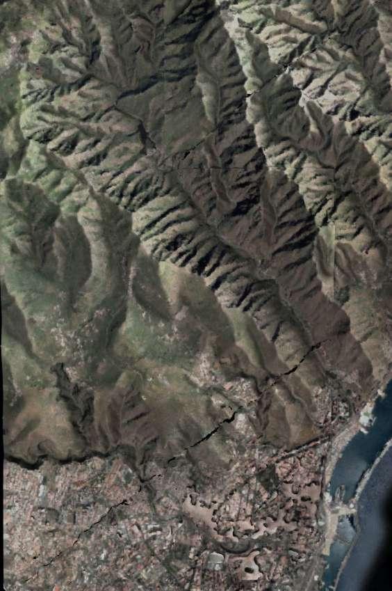
FROM URBAN TO RURAL TOURISM
As Tenerifes popularity grows as a tourist hot spot, the surge in hotel builds along the coast has significantly accelerated in the last decade. Tenerifes once natural coastline now aims to accommodates for a purely tourist based infrastructure that is focused around maximising revenue from a quantity based system. As a result Tenerife has subsequently partially lost its ’image’ as nature resort. The government of Tenerife has now initiated phasing and investment to push tourism in a new direction of rural tourism. Pushing to engage tourist with its varied biodiversity climate asides from the beaches which have become oversaturate with tourism. As part of this new brand of rural tourism a key component in the future developments as part of the project is to reclaim its title as a ‘nature resort‘ and therefore provide tourist based activities that strategies its engagement with nature and landscape.
“This tourist segment represents today a key point of support for the essential strategy of diversification of customers that the future of the Canary Islands needs,” Minister of Tourism, Culture and Sports Mariate Lorenzo.
NATURE TOURISM IN THE MOUNTAINS OF TENERIFE
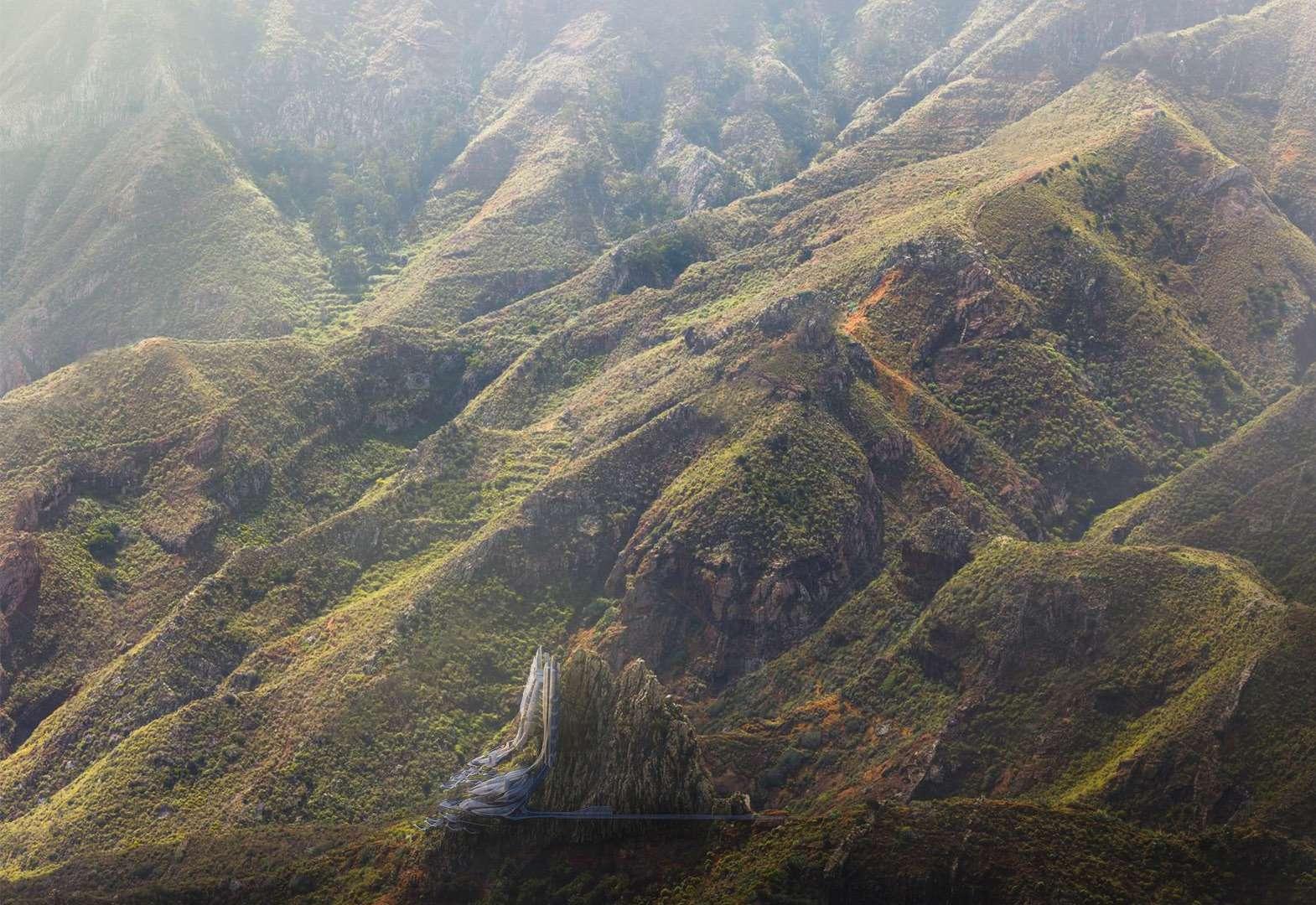
In tune with the re-branding of Tenerife as a natural resort, the government of Tenerife specifically has focused its attention on the inner unoccupied mountainous terrain of Tenerife. Previously untouched due to constraints of construction in the central mountainous terrain of the island. This project will aim at fulfilling the new guidelines of tourism in Teneife by engaging with the remote and biodiversity of the mountains of Tenerife. The project proposes not only an experience of this site but to provide a program based activity that ties you into the context itself. Subsequently the scheme provides a combined HOTEL-SPA experience where tourists seeking a remote engagement with nature can venture, whilst still only 4km from the nearest city.
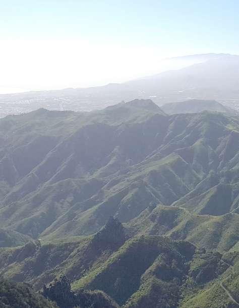
CHOSEN SITE: HOYA EL SAO
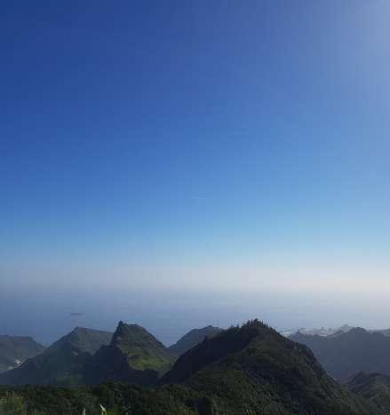
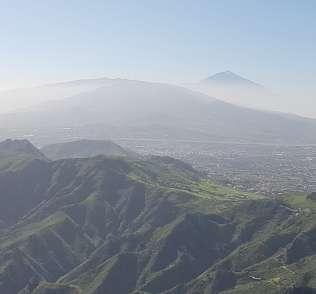
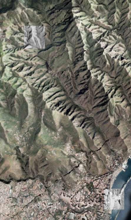
The chosen site is located in Hoya El Sao, the cliff is currently part of a landmark visit along one of Tenerifes popular hiking tracks. The site in particular was selected due to its stark protrusion from its surrounding landscape, and the unique experience that would come from inhabiting this extreme environment. This particular choice of site provides the project with a focus and testing ground for mountainous construction in Tenerife, developing a strategy of deployable in architecture in remote locations that can be used as a testing bed for any future mountain resorts in Tenerife as part of the islands re branding project.
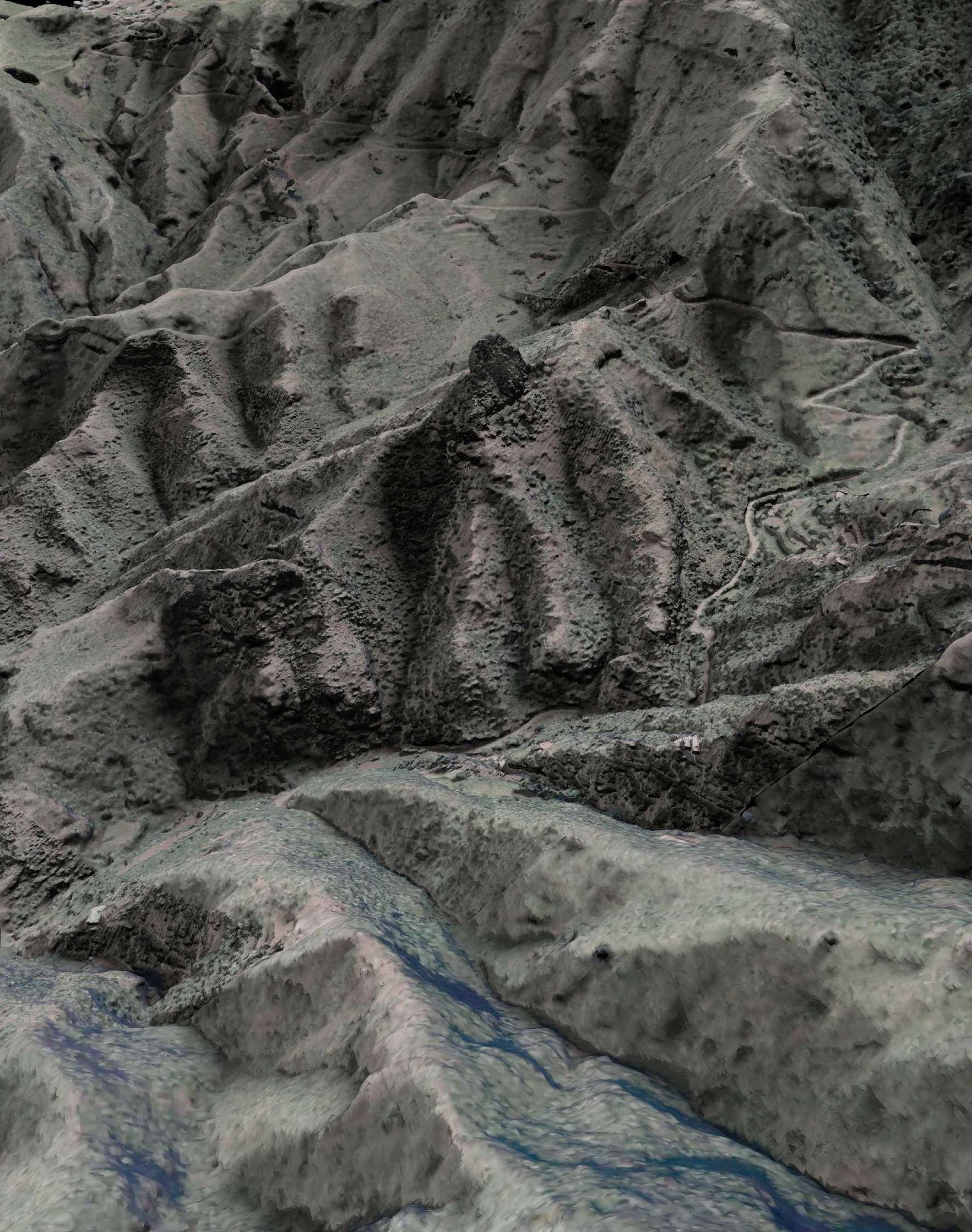

VIEWS
As of 2016, the government body of the island of Tenerife (Located in the Canary Islands) initiated a ‘rebranding’ proposal for tourism on the island due to concerns of a predicted decline in tourist activity as its beaches become overcrowded and oversaturated.
In the last 40 years, surges in tourism on the island have resulted in a significant increase in hotel builds along its beaches. As a result of this mass produced construction in the concentrated area of its coastline, Tenerife has gained a reputation as a ‘cheap and cheerful’ holiday resort for tourists from the UK, Germany and Scandinavia. The fear of the governing body is that further construction on its beaches will saturate this limited space, furthering this quantity based model of tourism that may eventually become unattractive to tourists.
To address this, the local government has proposed a new approach to tourism in Tenerife, focusing on a rebranding of the islands image as a ‘rural resort’. Through fewer but higher calibre of hotel builds spread throughout its mountainous terrain inland.
However, the proposed scheme has encountered issues, mainly consisting of difficulty of access and construction in these remote sites. A lack of infrastructure in the centre of the island and extreme terrain make construction of these high end resorts in these particular locations a significant challenge.
This projects will focus on deriving a methodology of construction and design for a luxury resort in a remote and topographically challenging site.
This project will act as a testing bed for a proposed build in one of these extreme mountain terrains. Aspects such as self-sufficiency in a remote locations and adaptability to the local climate play key roles in the design of the project.
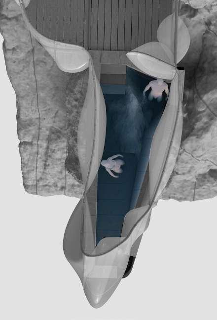
The proposed programme is that of a hotel combined with a spa. The program focuses on its interaction with the natural context through these external private pools , taking full advantage of Tenerifes year round temperate climate.
FOCUS : FORMAL APPROACH AND REASONING
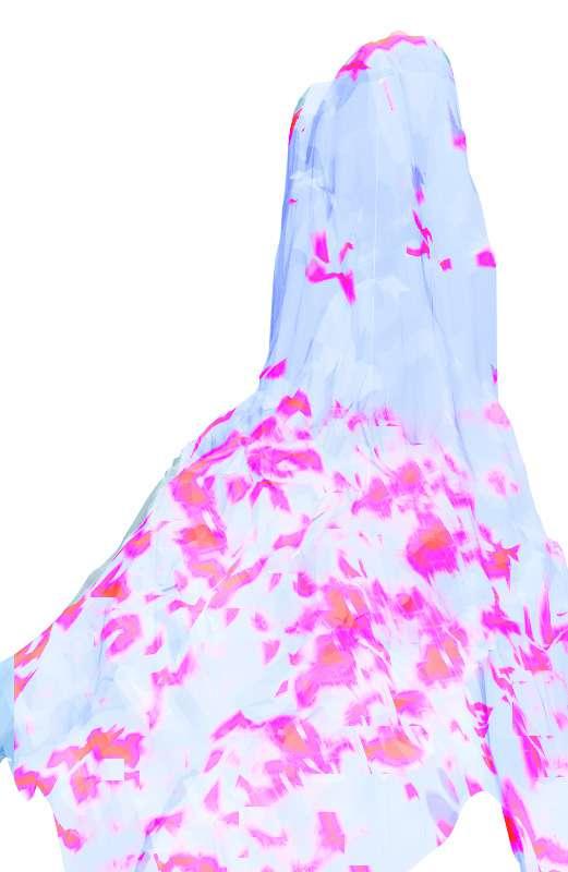
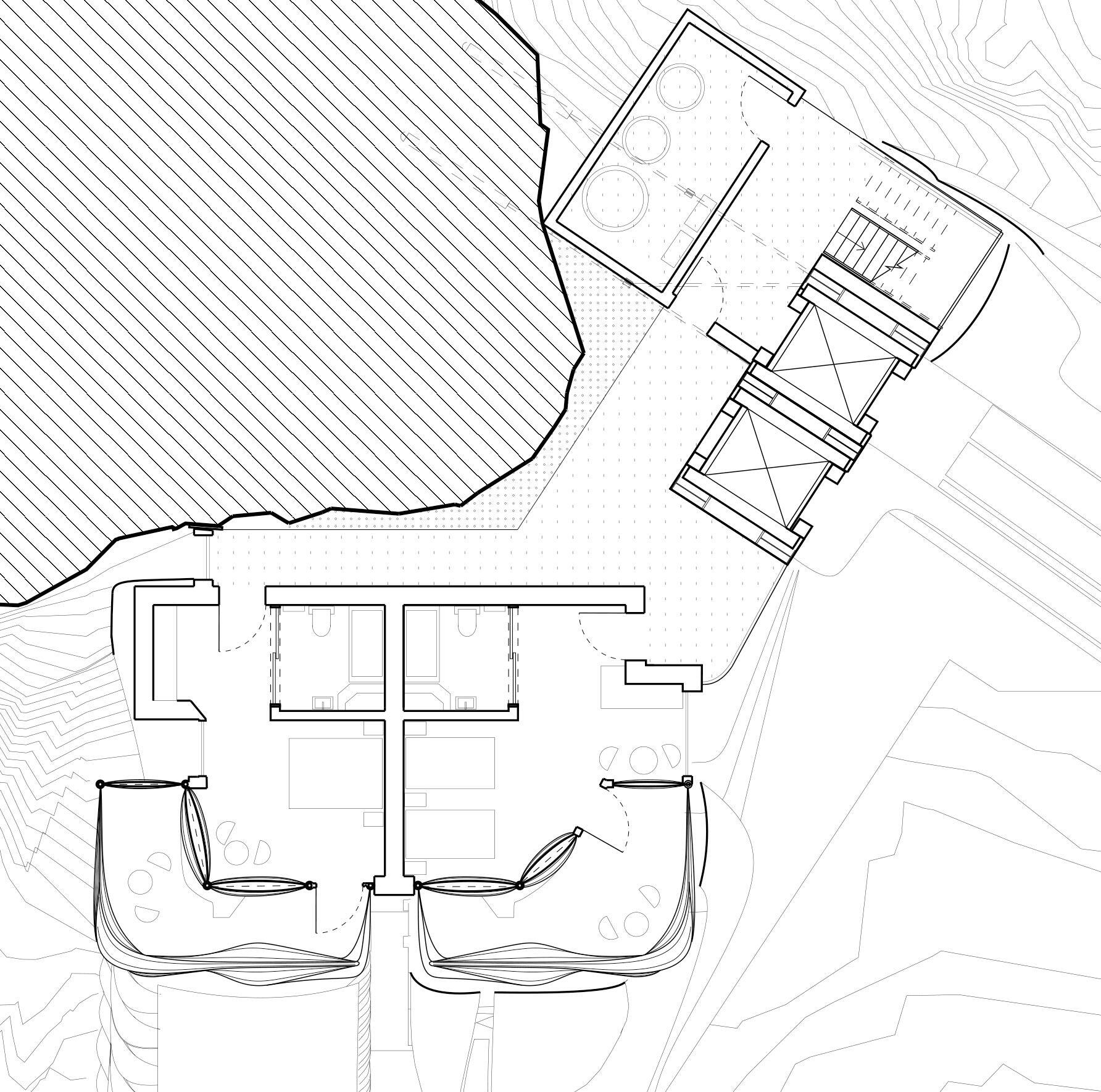
A steepness analysis was ran to determine areas of high degrees of horizontailty on which the building can rest on. The zoning of these areas influenced the massing of these programmatic spaces.
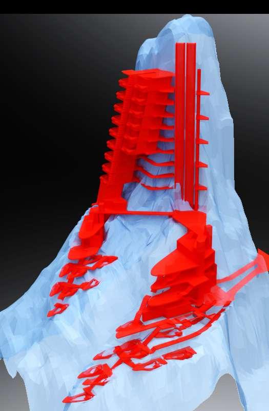
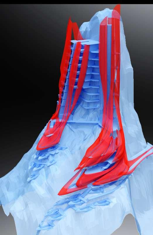
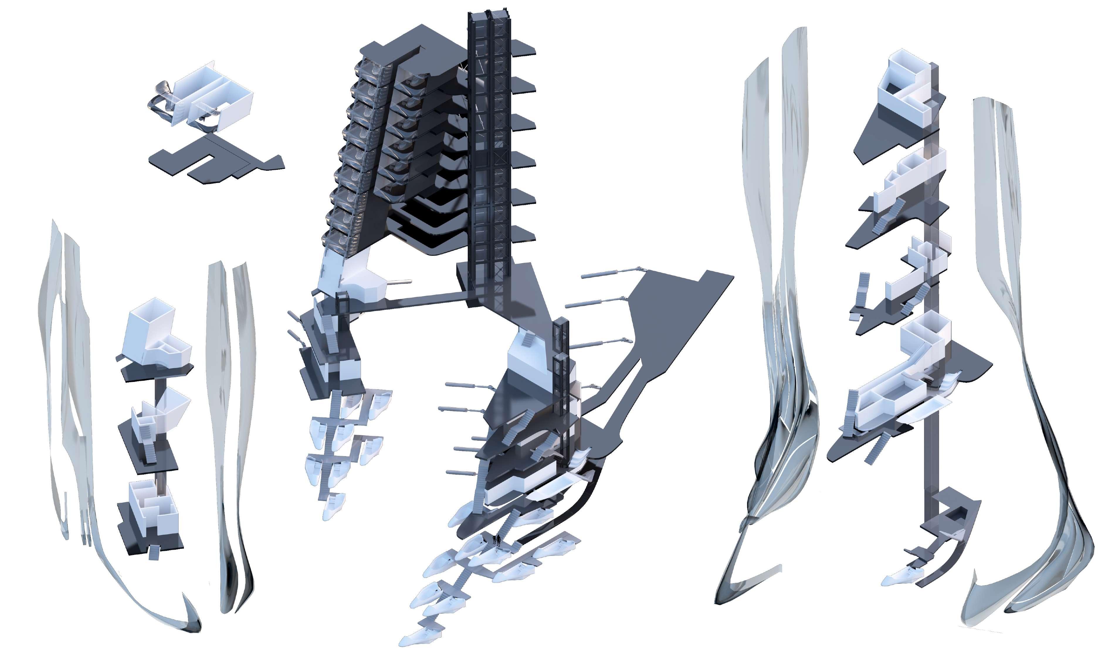
Floors and walls are placed based on the programmatic, circulative, environmental and structural requirements of the building.
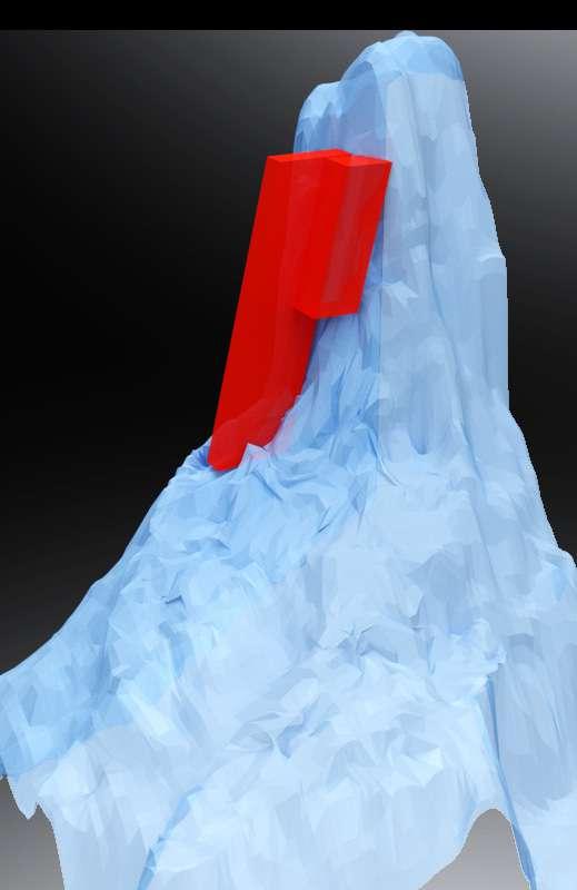
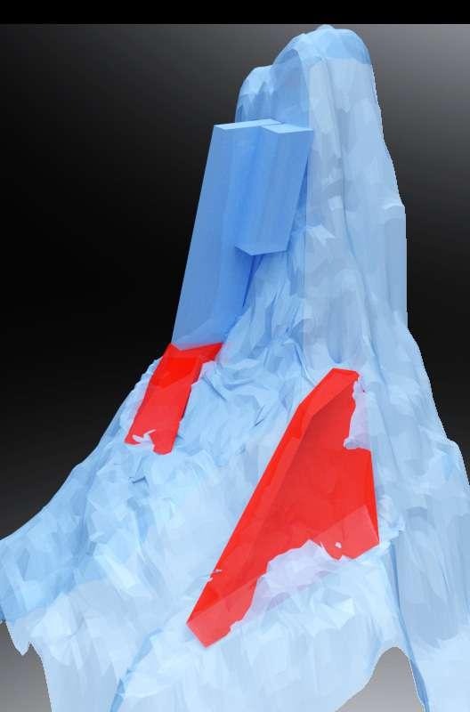
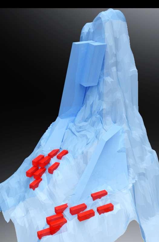
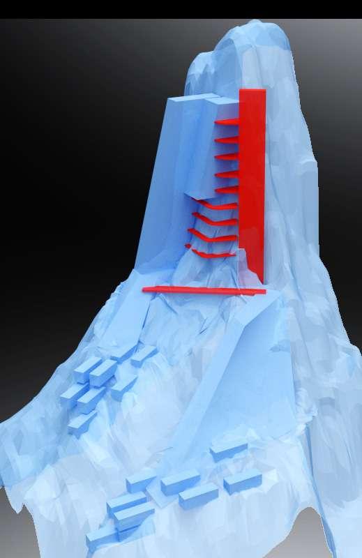
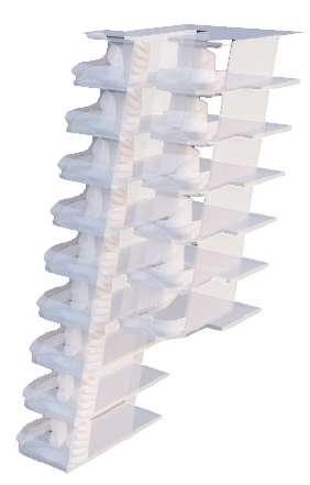
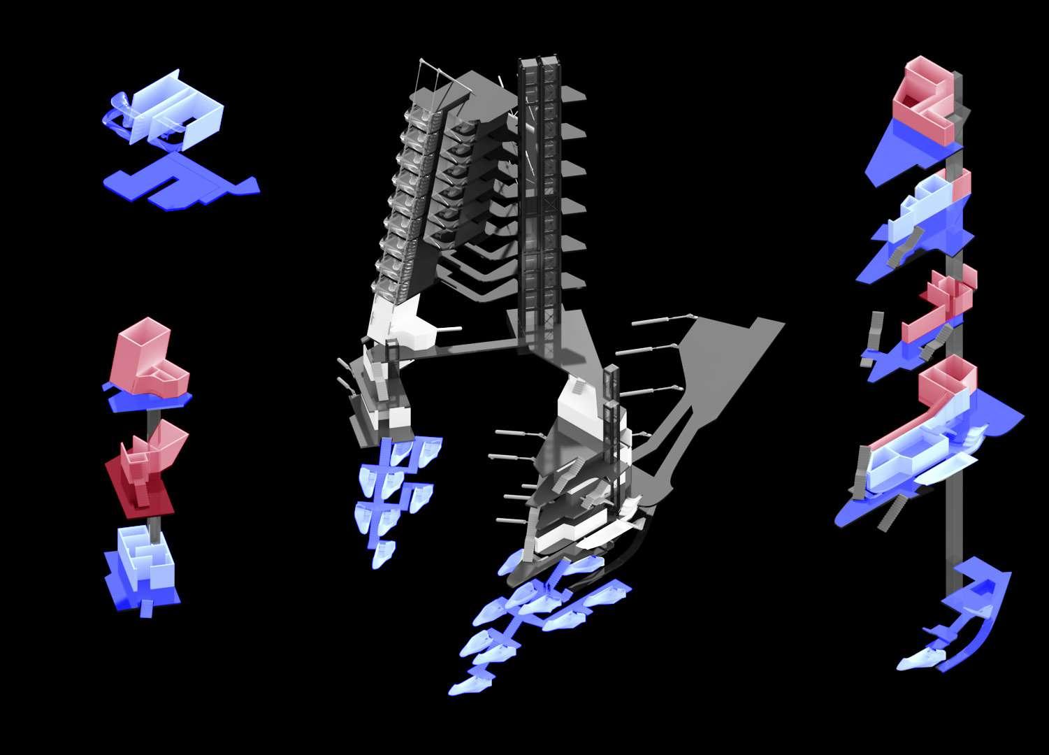
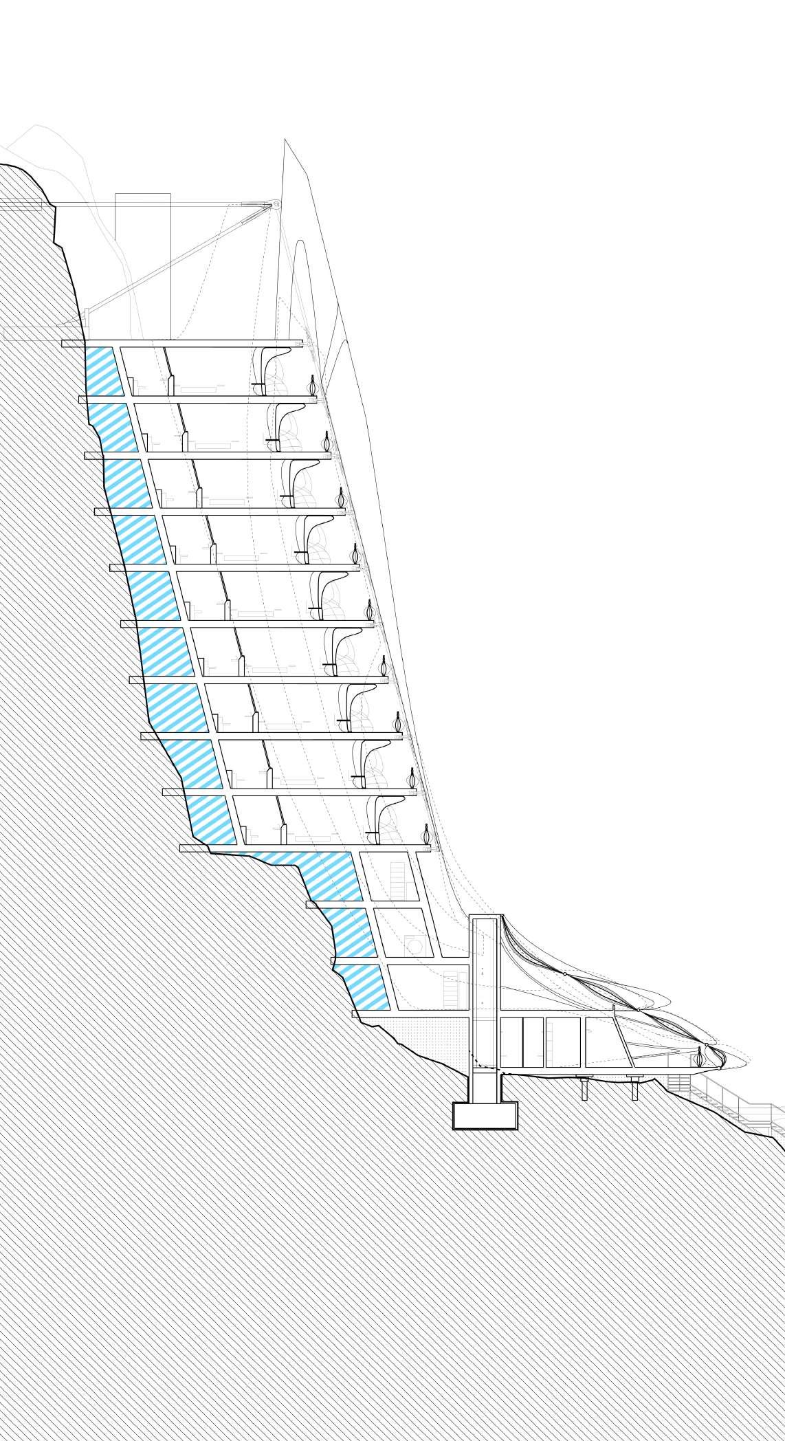
The hotel pods stacked vertically take on the angle of the cliff at 110 degrees. The placed pods run the whole length where possible but in certain areas where the rock protrudes too far the rooms cannot be stacked. Floor surfaces are then covered with a skin over the programmatic spaces and the hotel rooms.
The massing of the programmatic spaces are placed lower down on the cliff and are located in the zones of highest degrees of horizontality.
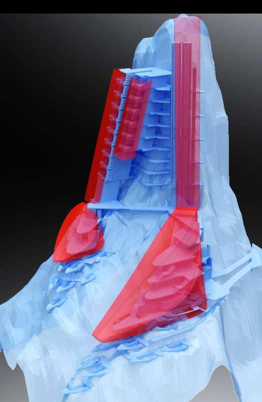
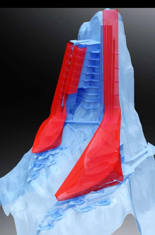
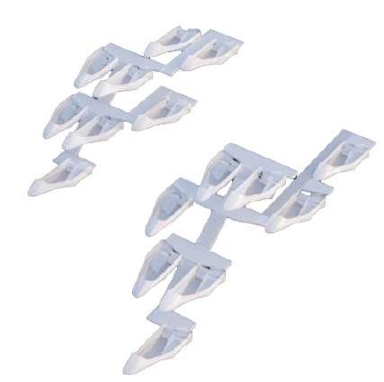
The location of the pools is a combination of situating them in horizontal niches where they can rest in, and maintaining suitable distance and proximity from one another for ease of access.
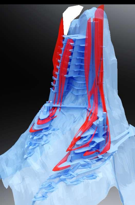
Once the basic massing established, vertical and horizontal means of circulation are introduced.
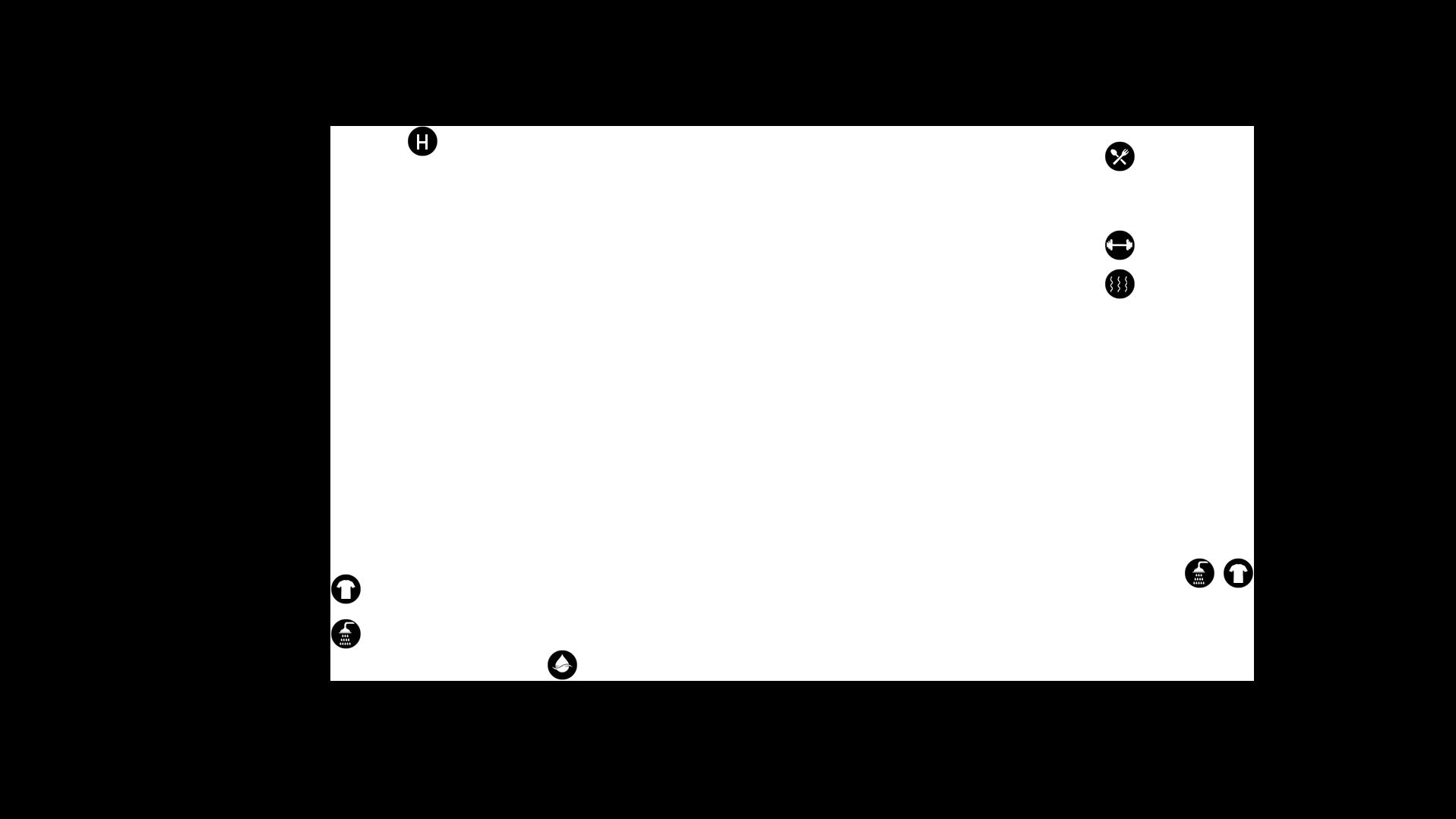
CHANGING ROOMS
1.11 FOCUS: ADAPTIVE SKIN (VERSION 1) (SUPERSEDED AS OF 12/04/2020)
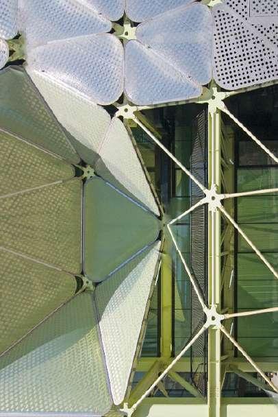
MEDIA TIC, ETFE SYSTEM
The developed hotel facade system was developed based on the media ITC buildings ETFE facade, which acts a enviromentally performative secondary skin.
The south, east facing facade which absorbs six hours of sunlight a day provides protection from the exterior heat using a ‘diaphragm’ configuration of ETFE cladding, whereby a multi layered plastic sheets are fixed within a frame and inflated like a pillow. A dotted pattern applied between the layers contains multiple air chambers that create a shade-effect and prevent the building from overheating.
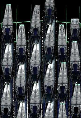
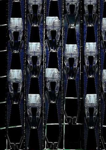
ADAPTED SYSTEM
The adapted system used in the building relies on a similar principal of a multi layered ETFE surfaces. Contained and sealed in an encompassing frame that is then attached on to the secondary skins structure which hangs of the primary anchor structure. The ETFE ‘skin‘ is inflated through air pipes inserted between the layers which is then linked to an mechanised sensor that controls the air flow. Depending on the time of day and overall temperature the sensor triggers varying air pressures that can either inflate or deflate the panel and hence regulate the temperature of the veranda which subsequently controls the amount of heat transmitted to the rest of the building through the passive heating system.
The panel frame is a single mass produced piece made from steel sheets which would be cut out using water-jet cutting
The frame contains pivot connections to the side to allow horizontal rotation along the surface.
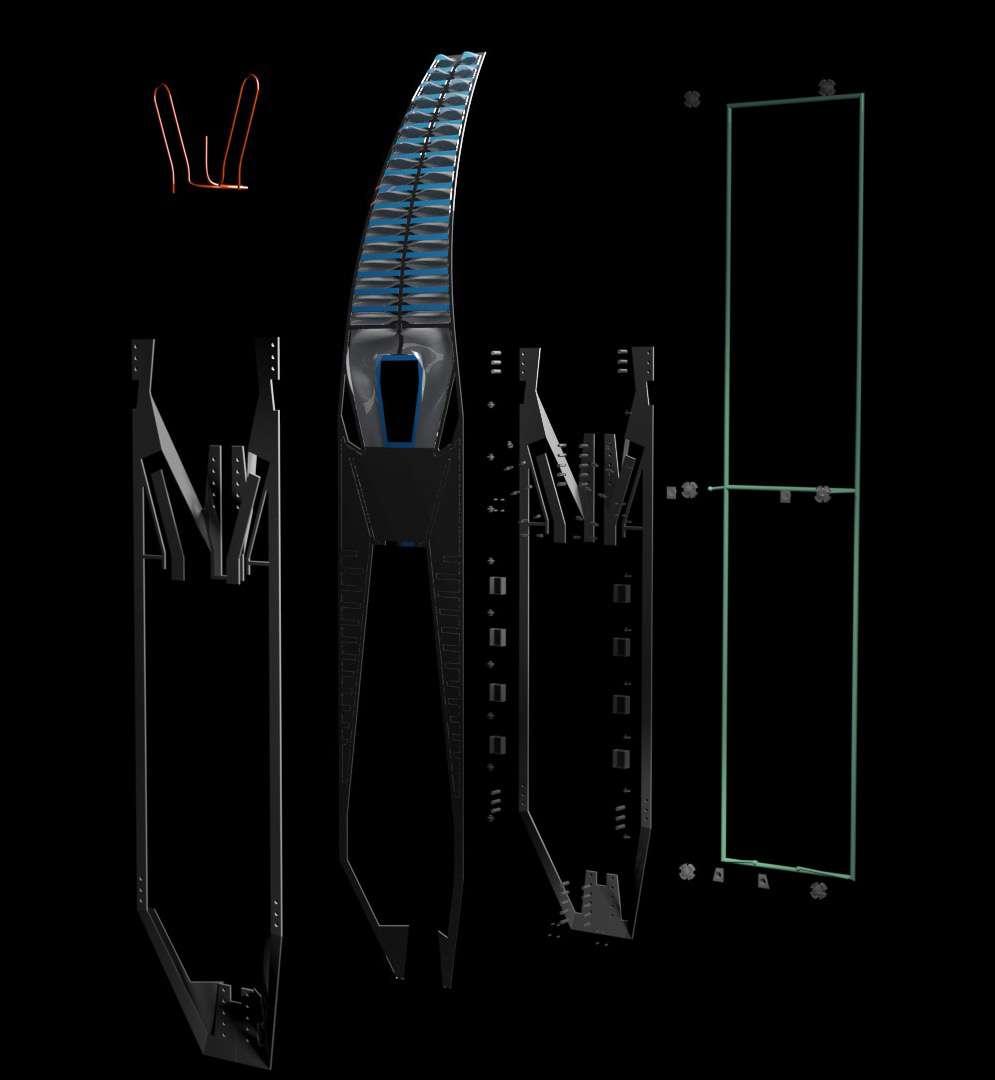
CONSTRUCTION
fig 7 Media-TIC Building Designed by Enric Ruiz Geli, Cloud 9, Barcelona
HOTEL ROOMS
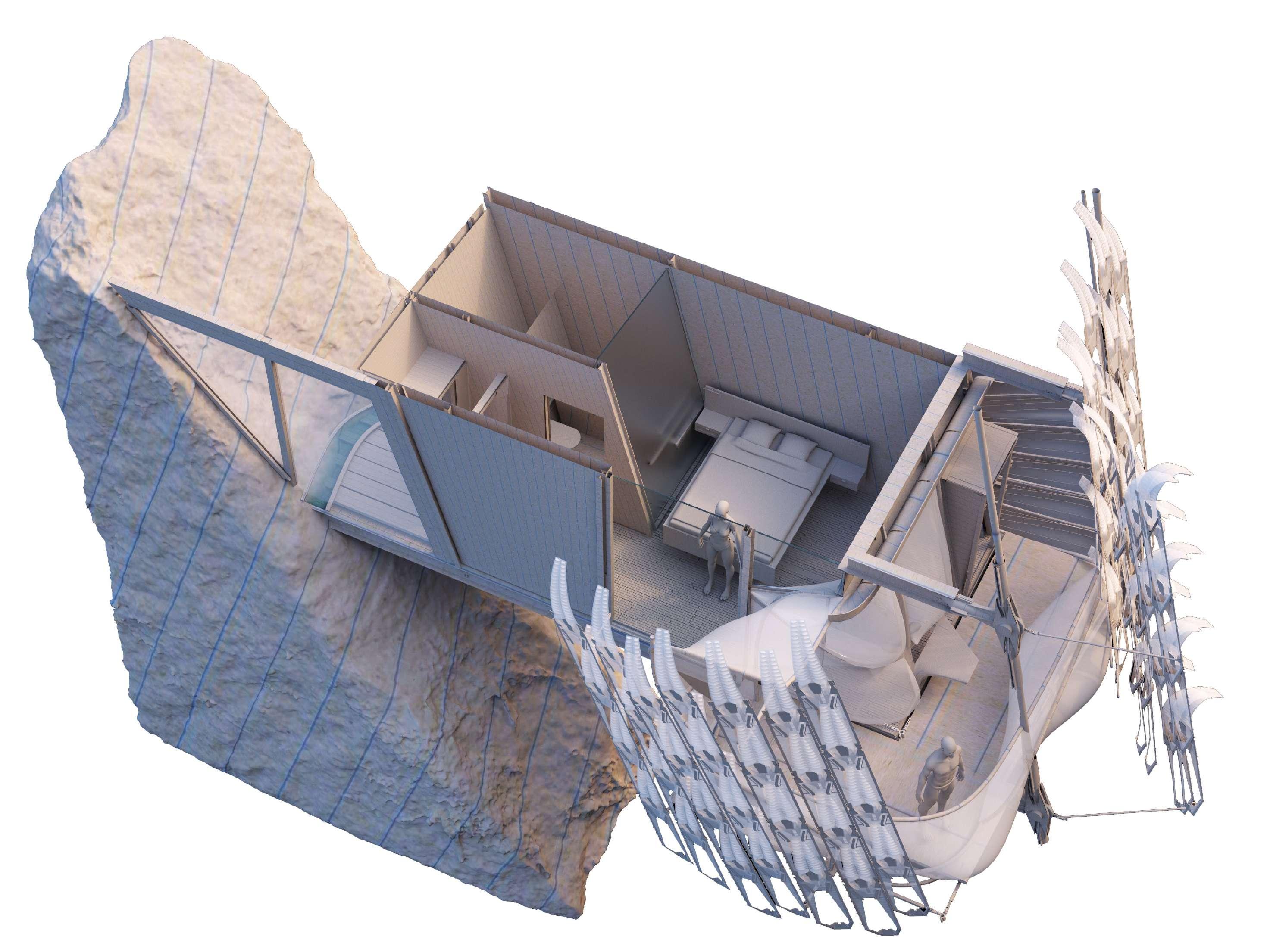
The layout of the hotel rooms is primarily based on 2 constraints, being south facing to maximise the solar harvesting of the secondary skin. Secondly how the skin is placed so as to only partially cover the tower so as not to obstruct key views from the room. The overall form of the vertical skin along the tower is based off of a balance between these two aspects.

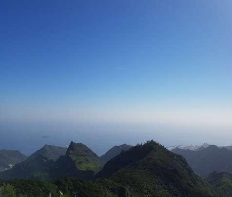
The south facing view provides clear views down to the sea and a partial view of the city of Santa Cruz located to the right of the image. The stark contrast between mountains and sea will also serve as a compelling advertisement imagery for any promotional shots displayed when advertising the hotel-spa. The view additionally feeds into the much desired seaside view when staying at any hotel.
FRAMING VIEWS THROUGH SKIN
Each room contains a total of 2 framed views, one looking south onto the seaside coast (a), and one looking either east or west on to neighbouring mountains (b).
One of these views being internal provides a direct view either East word or Westwood from the bed.
The secondary view is based from the external terrace and offers views south onto the sea.
PARTIAL COVERING OF SECONDARY SKIN
The performative secondary skin is applied in front of each room when matched with an ETFE layer behind it leading onto the terrace. This is critical as to the environmental strategy discussed in the following page 1.13. The skin opens up onto the room when a glass window is placed so as to liberate an unobstructed view of the surrounding scenery. This partial covering feeds into a an aesthetics language of partial covering. Areas such as the south facing room are deliberately covered to maximise its solar harvesting capabilities.
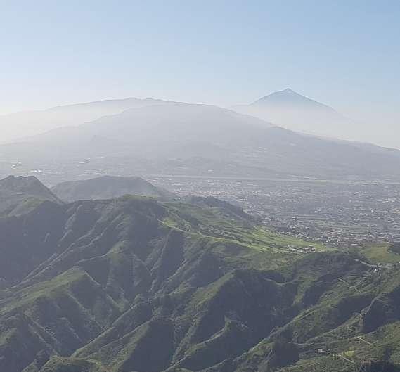
The west face from the bed offers a mountainous view of the surrounding topographical landscape, furthermore contrasting against the famous volcano in the back. A key tourist feature in Tenerife. The view itself from which the picture was taken is widely known in Tenerife as a unique hot spot for providing an all encompassing view of both open-spread mountain range an the contrasting sea with the further distant volcano prominent in the background. This key view which provides a continuous attraction for tourists would also lead to an increased popularity of tourists inclined to visit.
WEST FACING ON TO VOLCANO
WATER CIRCULATION
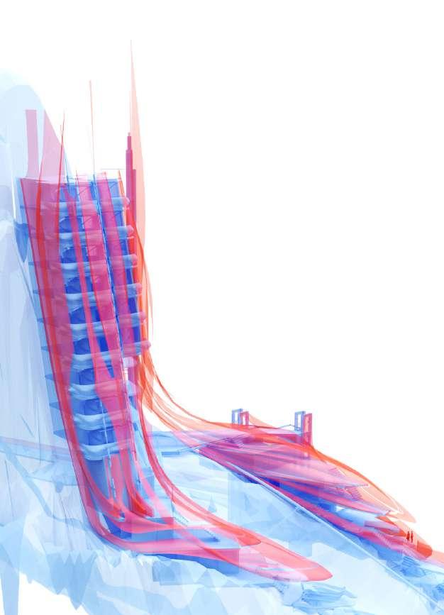
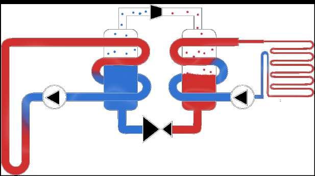
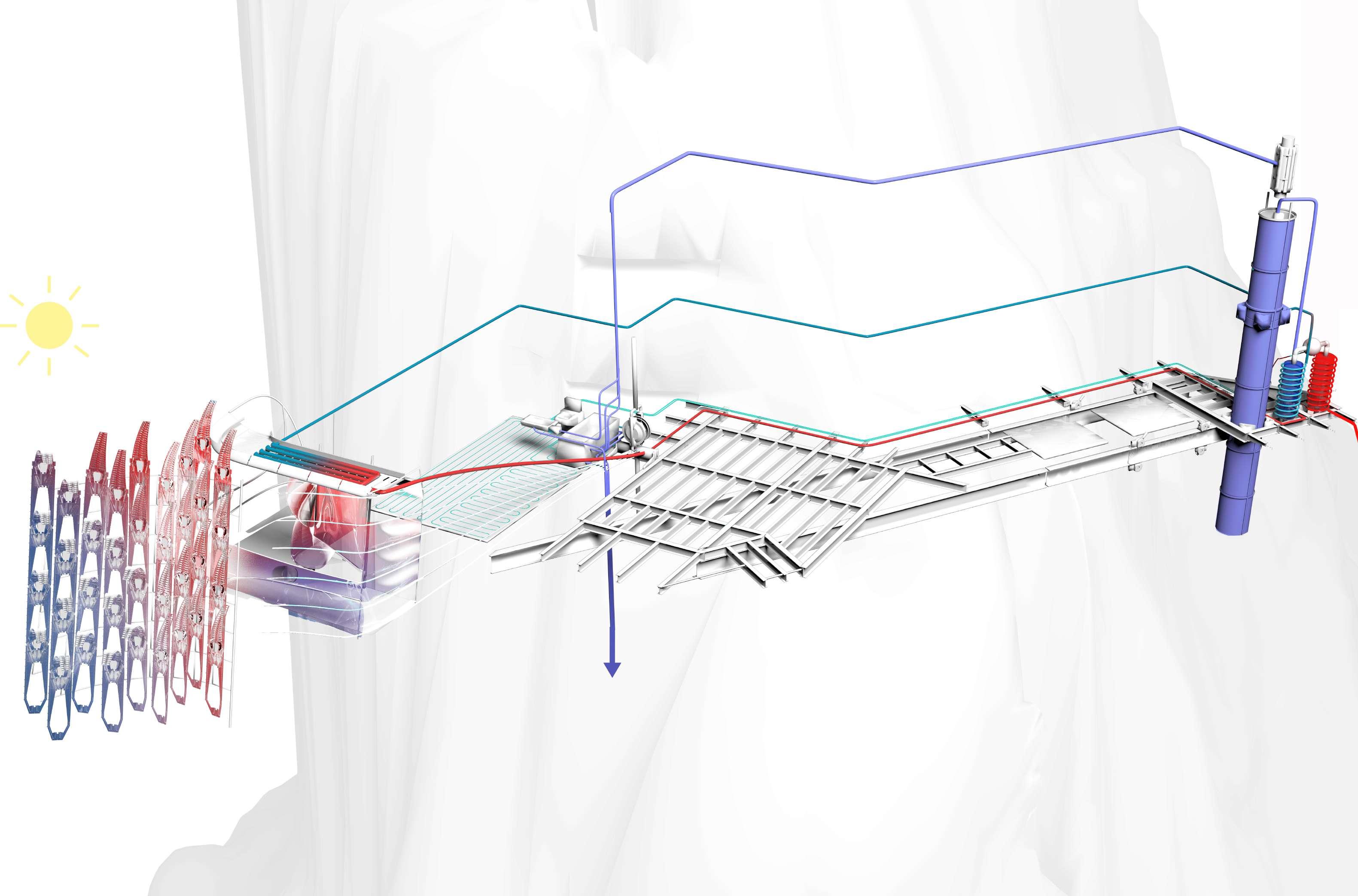
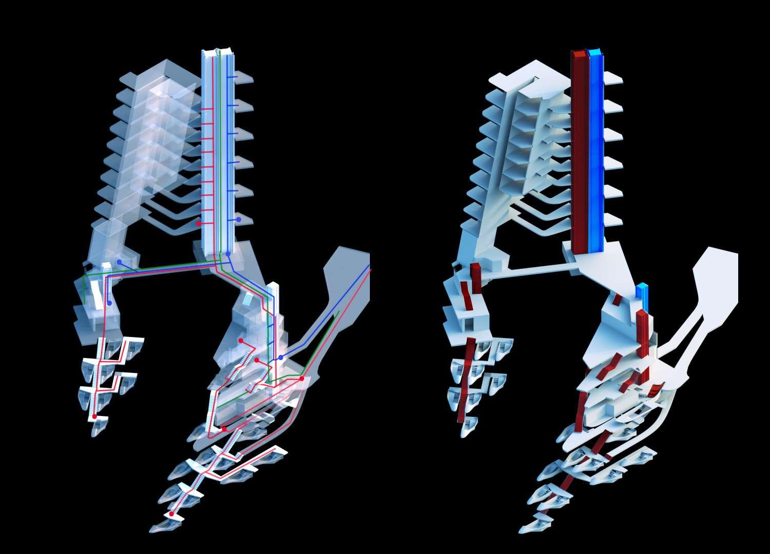
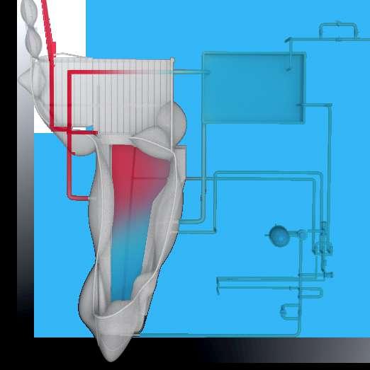
The purpose of the solar harvesting skin and its heat harvesting is to then heat the water needed for the pools. As water is pumped up to the hotel where it is filtered and then heated through the air source heat pump. The water is then distributed via pipes that are integrated on top of the skins secondary structure.
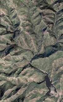
1.2 KM
SOURCING WATER
The water sourced for the building is pumped from the Embalse de tahodio reservoir less than 1.2 km away. This reservoir acts as the main source of water distribution to the city of Santa Cruz located a further 3km south of the reservoir. The reservoir has a capacity of 900,000 cubic meters of water. It is located about 250 meters above sea level and stores runoff water from one of the largest hydro-graphic basins of the Macizo de Anaga area.
PEELING LANGUAGE
The resultant form of the skin and subsequent dispersion of elements were informed by the required placing and circulation of the water pipes which plug into the pools below. Creating a complete circulatory system. Grey water is recycled as part this system, and all water is pumped up through the filtration towers. Water can then be distributed down to the pools simply by gravity.
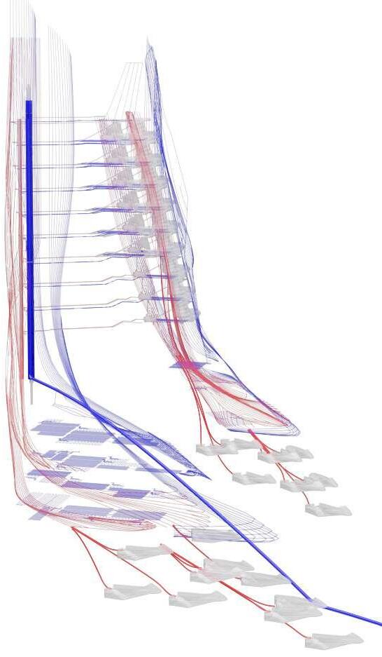
Pipes are separated to transfer either hot or cold water down the facade, the use of both hot and cold water allows the air source heat pump to work most economically through this balance.
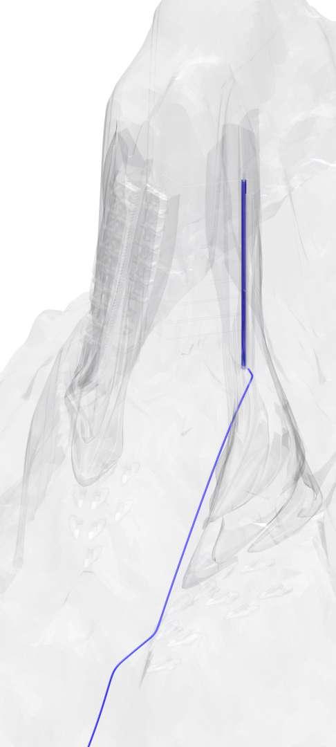
PUMPED UP
Water is pumped from the reservoir up the tower where it passes through a filtering system during it upwards trajectory.
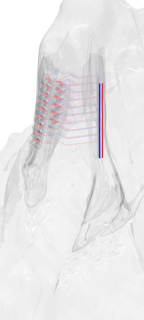
Water is then passed through the air source heat pump pipe system to gather heat from the heat trapping skin-balcony strategy.
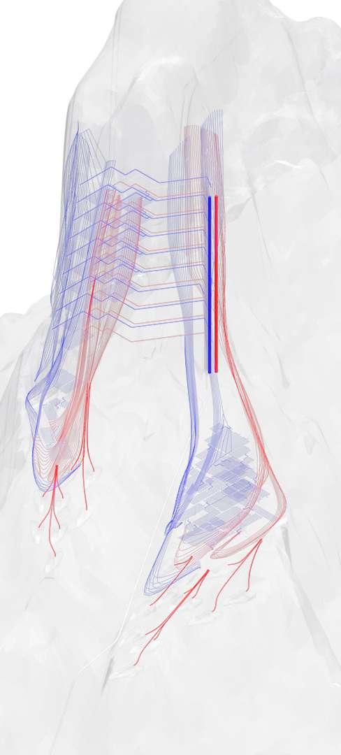
and
The pools allocated around the southern part of the cliff are based primarily on the steepness analysis in 1.04, to determine areas with high degree of horizontal faces to allow for a partial inclusion of the pool into cliffs protruding rocks. The pools partially rest on the rock to minimise the size of the anchor used in restraining the rock to the cliff face.
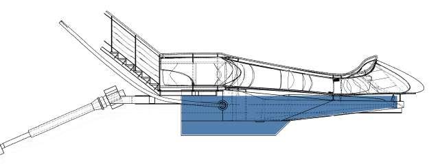
The overhanging pools contain 3m3 coming up to a weight of 3000 kilos, the weight of two average sized cars. Both the placed anchors and any supporting rock are used to help support the overhang. The largest mass of the water remains closest to the rock where it can sit within and reduce overhang weight. Therefore only 1100 kilos of water is overhanging with the remaining 1900 helping balance out the cantilever.
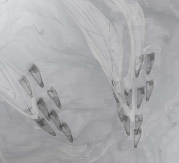
The arrangement and resultant spacing of the pods is the result of a calibrated balance between the results from the steepness analyses to determine the most suitable areas to lodge the pods and standard stair regulation which would determine the landing for a pod cluster.
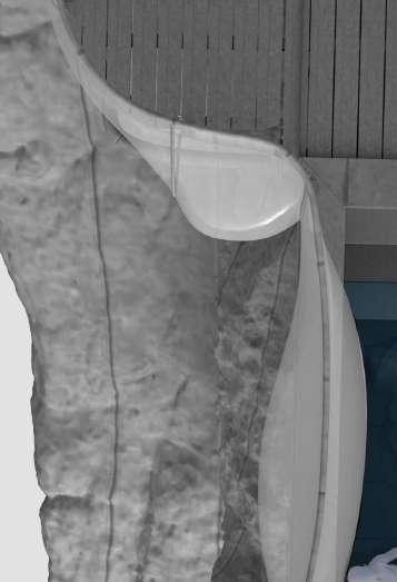
The objective of the pools is to provide a new form of interaction with a landscapes that previously remained inaccessible to humans. Through this new engagement with nature, the resort will focus on providing non-standard, unique experiences in nature that blend building technology in extreme locations, combined with the natural experience of the site.
Heated water is pumped down from an activated air source heat pump located in the building further up the cliff.
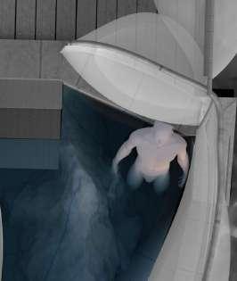
VS HARD
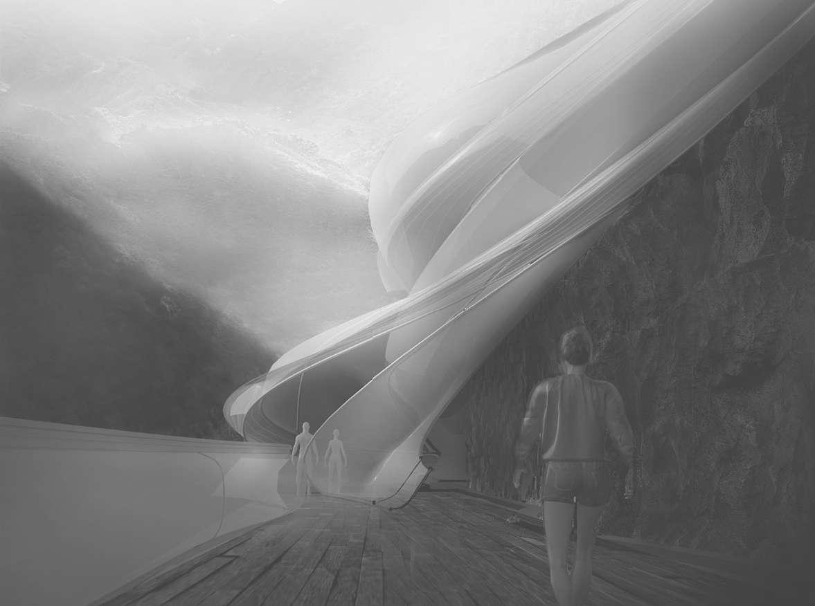
ETFE used is used for weightlessness qaulities which contribute to the desired aesthetical language of the project, a contrast between the roughness of the rock and softness of the ETFE pillow inflatables.
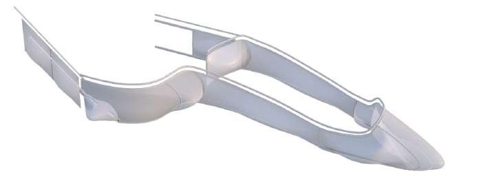
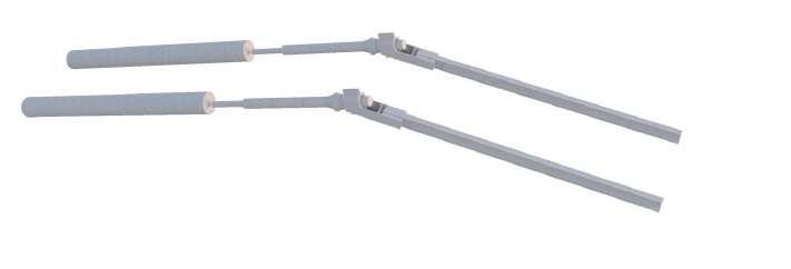
Balustrades surrounding the pools are composed of cushioned ETFE sheets. Primarily used for its weightlessness the pillows also provide a tactile and soft surface for users to rest on whilst allowing for partial views in araes via its translucent qualities onto the surrounding scenery.
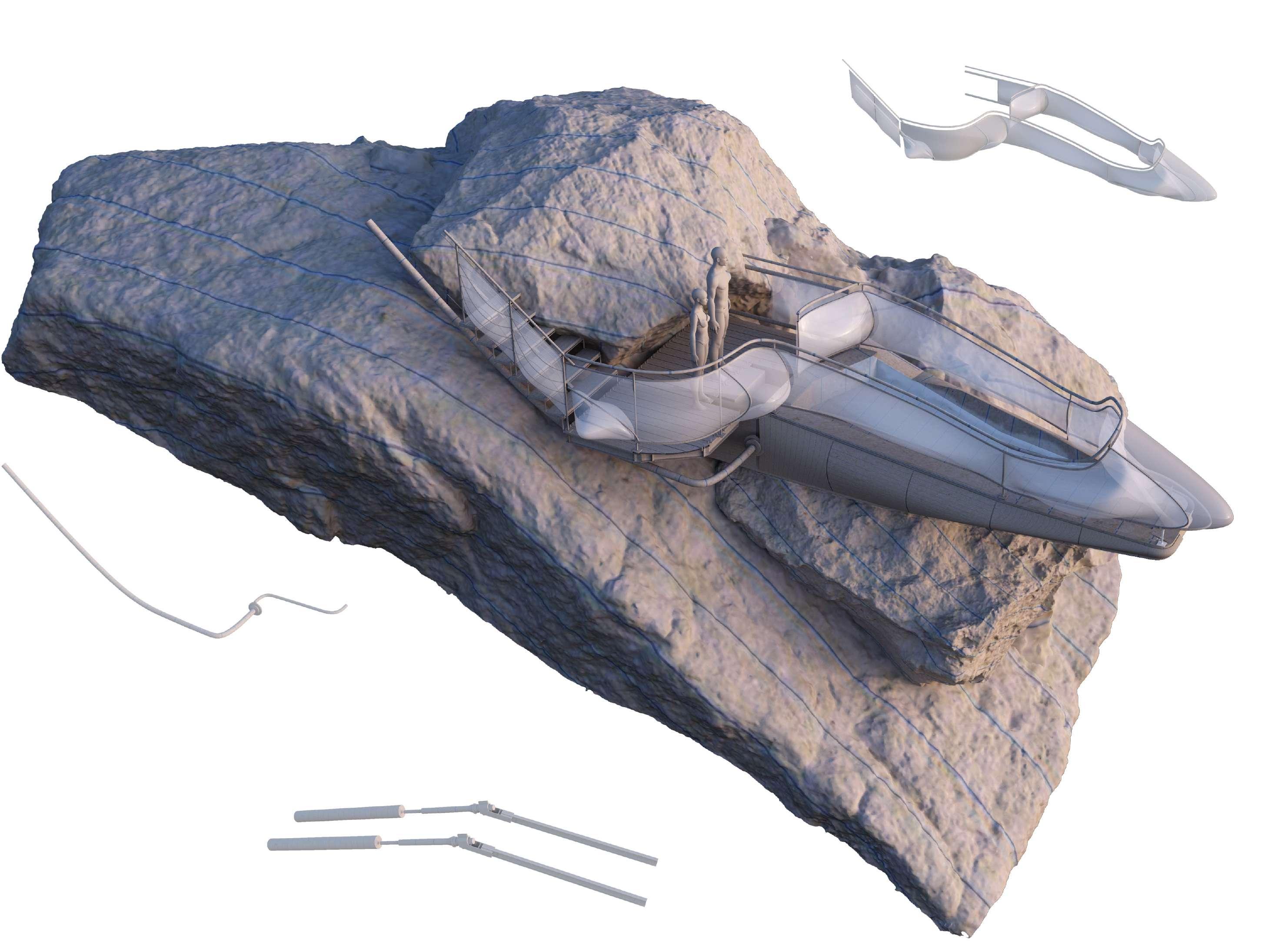
The primary strategy used in the grounding of these pools is the placement of ground anchors into the rock from with which the pools can counter-leaver off of and cope with the heavy load of the water. Pools are nested into the rock and contribute to assisting with any overhang. Anchors further specified in chap 2.
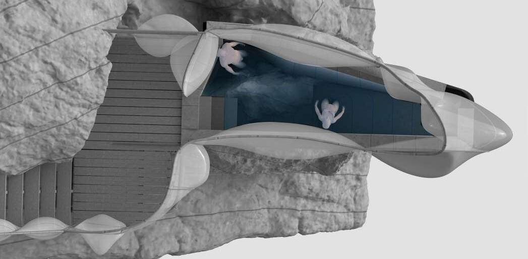
Due to the steepness of the cliff and length of the pool, each pods overhangs partially off the cliff to provide the users with a completely unique experience for every spa user. Whereas most spa pools are deeply rooted within the earth, these pods take on the challenge of a hanging pool experience to further immerse the user within the mountainous relief of the context and accentuate an unmatched experience. Further accentuating the natural connection of the site by accentuating the users experience through its steepness that qualifies the mountainous context it resides in.
HANGING POOL
WATER SOURCE CUSHIONED BALUSTRADE ANCHORS
POOL LAYOUT STRATEGY
SOFT
3m3 of water
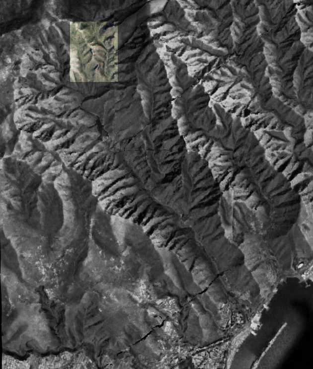
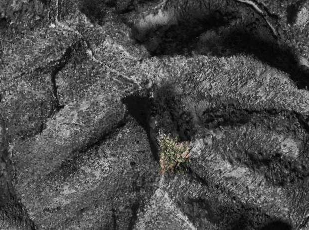
The material choices of the building aims to contrast the ‘soft‘ cushion aesthetic of the ETFE with that of the rough surface of the cliff. To further integrate elements of the building the excavated rock from the construction process will be reused where possible as flooring and wall finish.
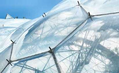
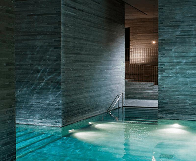
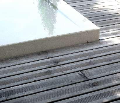
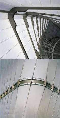
ETFE will be used primarily for its weightlessness, translucency and inflatable qualities that allow for both daylight and for the environmental system of heat harvesting to take place
Rock excavated during construction is to be turned into tiles as a finish for the buildings internal walls. The use of reused rock will help reduce overhead cost. Tenerife hosts a quarry south of the site which will manufacture the rock into tiles.
Areas that require for a more lightweight finish such as cantilevering portions will use timber decking. Particularly suitable for the pools which will help reduce slipping through patterned floors. A natural material will further enhance the nature driven experience of the pool.
All of the ETFE pillows will contain a lightweight galvanised steel structure to hold and seal off the pillows through extruded almium restraints. These steel frames will be used to accentuate and highlight the pillows themselves by distinguishing each pillow through the stark contrast of steel and ETFE.
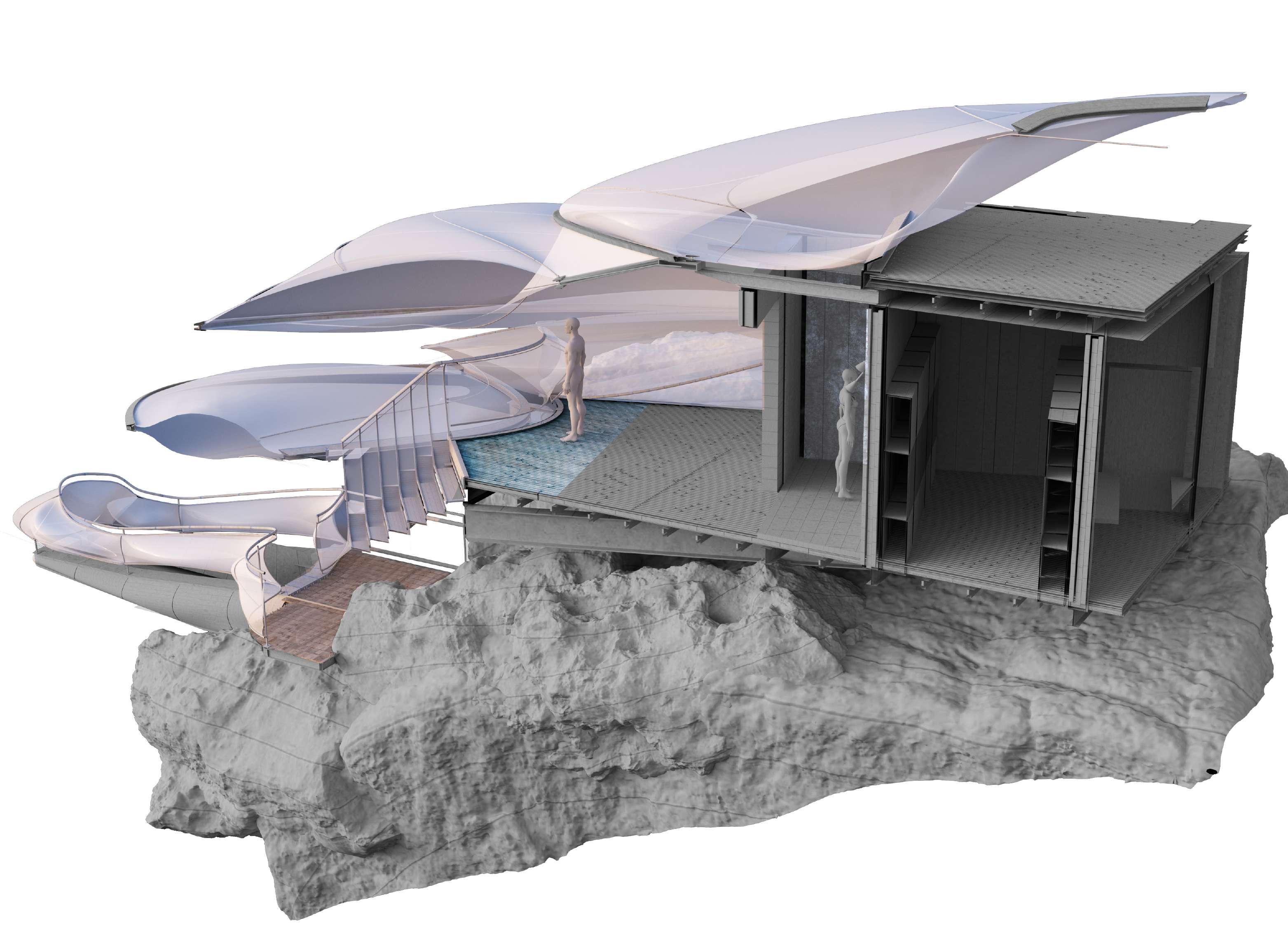
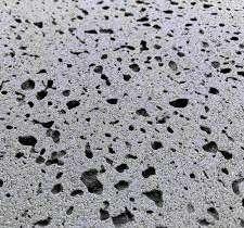
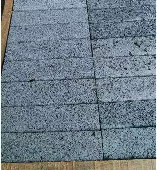
IGNEOUS
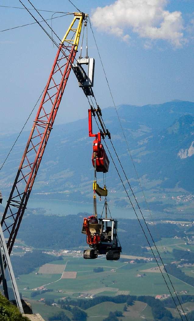
Cable cranes will assist in the delivery of elements that do not require the use of the air crane, mainly for cost reasons and time constraint of delivery. The helicopter will be used to deliver components either to a main drop off bay that is easily accessible and flat as well as assembly through direct delivery or directly on site where the component is detached and assembled in place.
The use of cable cranes will allow the project to minimise the impact on the landscape by not having to construct additional roads through the terrain to gain access to the construction site. In most cases, cable cranes are completely de-constructed once a project is completed therefore allowing for minimal traces of their use.
Using a cable crane means heavy machinery can access steep and dangerous terrain without the need to travel on dangerous access roads providing additional safety during construction.
Through the use of cable cranes materials can be safely delivered through the terrain to the construction site in an efficient manner. Not only is it possible to transport machinery from point A to point B (e.g., from the valley to the mountain), but the loads can be unloaded at any point along the track, proving to be useful for various locations of construction on site.
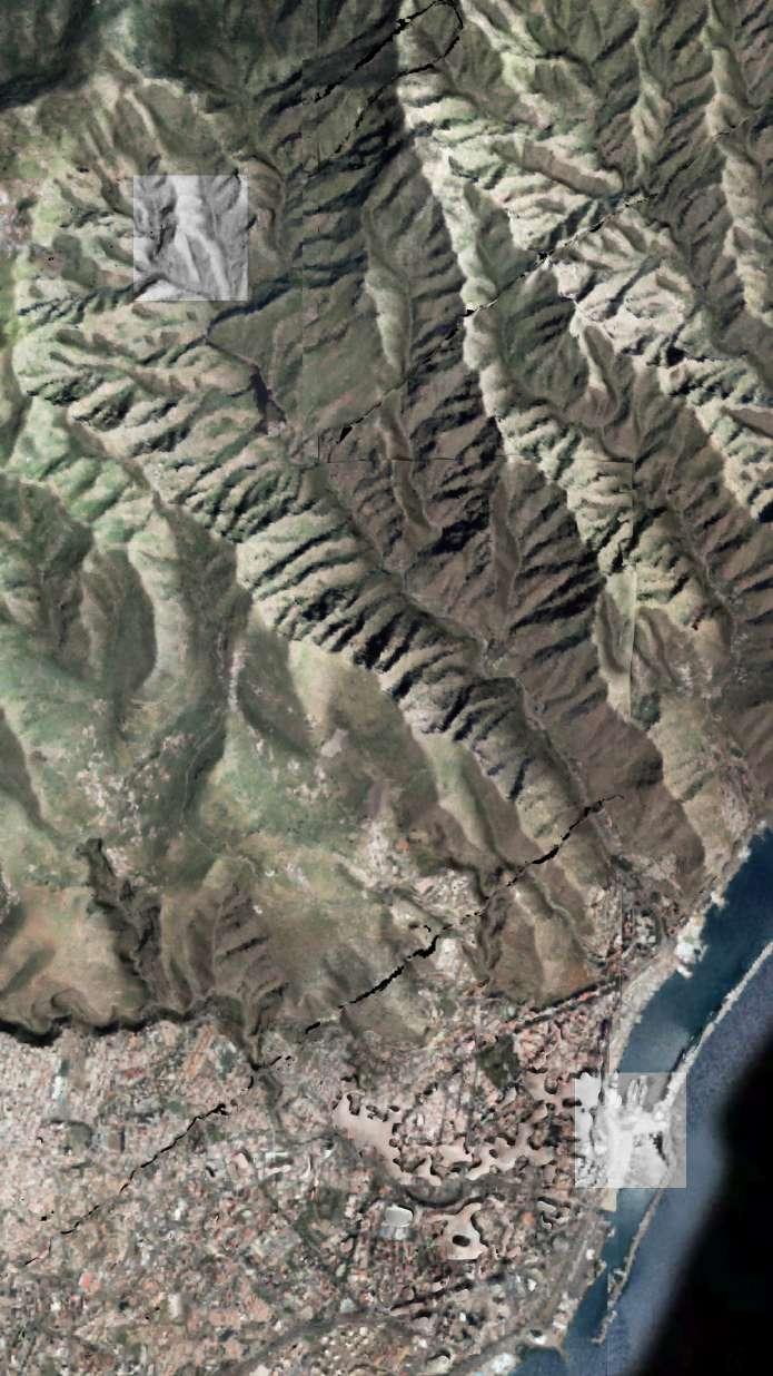
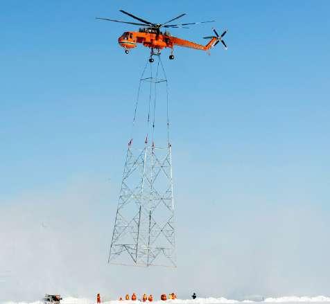
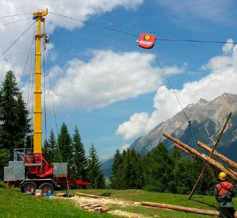
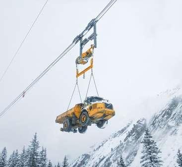
A large open space that is cleared of debris and any items that can be swept or damaged by the wind forces caused by the helicopter acts as one of the drop off zones. The site selected for the unloading is 280 m from the construction site.
on the nature the load. Once delivered to the drop off zone or the site itself, the items will be placed on to cable cranes to further transport them up the mountain.
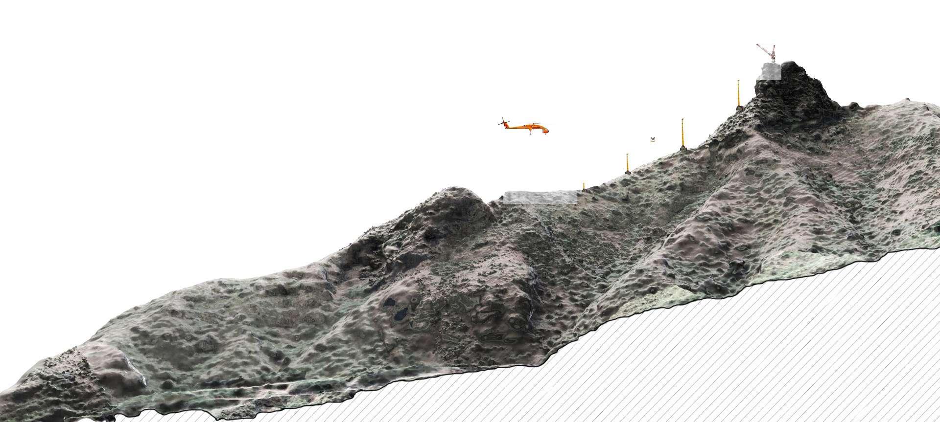
The
The top of the cliff consists of an approximately 13m by 6m platform upon which a temporary crane can be anchored to lower workers when drilling the excavation of the site. The crane can be fitted into the excavated zone that will later be used by the main anchors used to uphold the tower.

This delivery zone does not contain road access. Therefore the mobile cable crane is to be fitted with workers cable cars to transport the worker down from the building construction site to one of the delivery sites. Further details as to the operation of this site in chapter 2.
CONSTRUCTION SEQUENCING
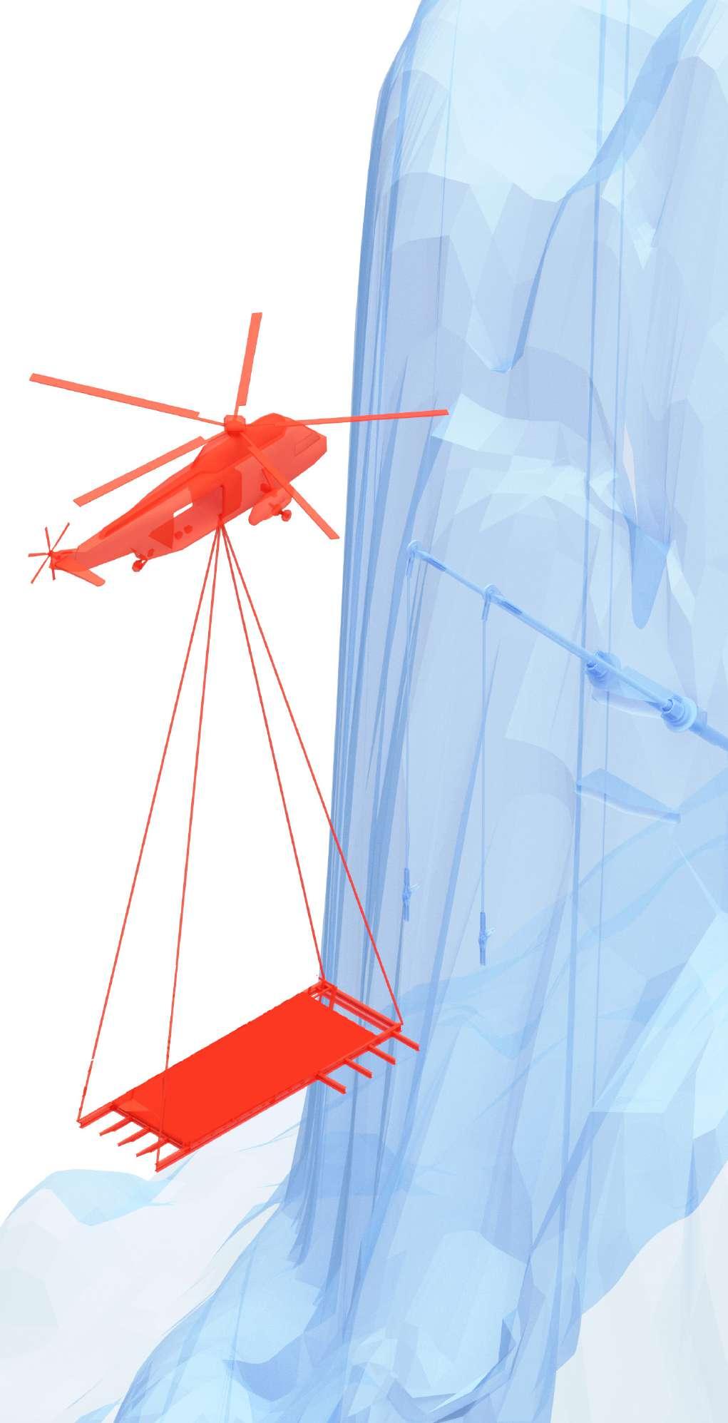
The majority of the build will constitute of pre assembled components that are delivered to site via air crane and then assembled through fast assembly joint systems. The construction sequencing will be a combination of air cane delivery and cable crane delivery.
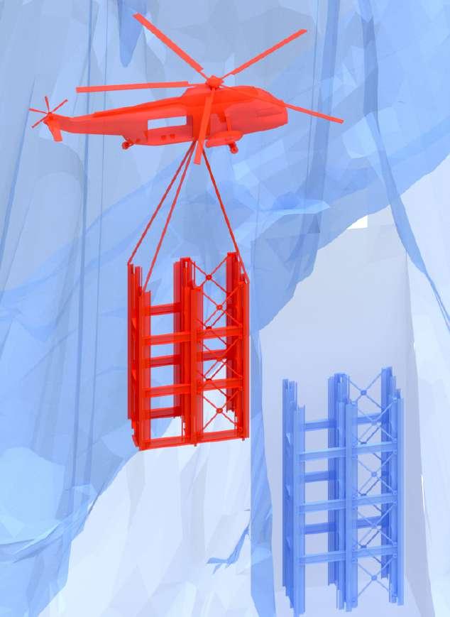
Prefab steel core installations
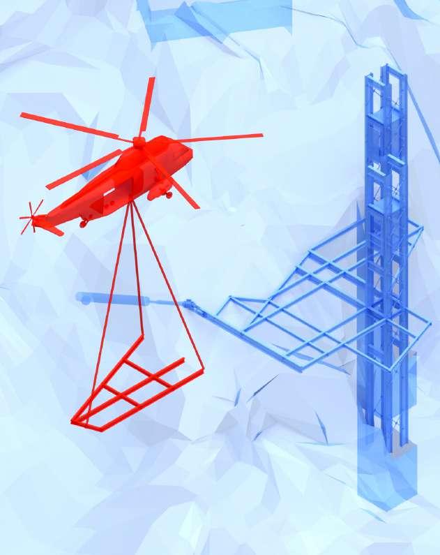
Steel beam structure delivery
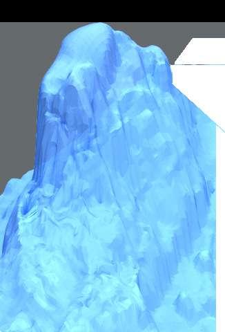
Through the use of a 3D scanned model of the site acquired prior to the design phasing. Markers are placed around the site and into the cliff to establish guidelines. Site is the secured by closing off the main access route to working personnel only. The hiking route along the cliff will be temporarily re directed.
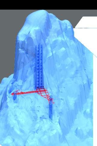
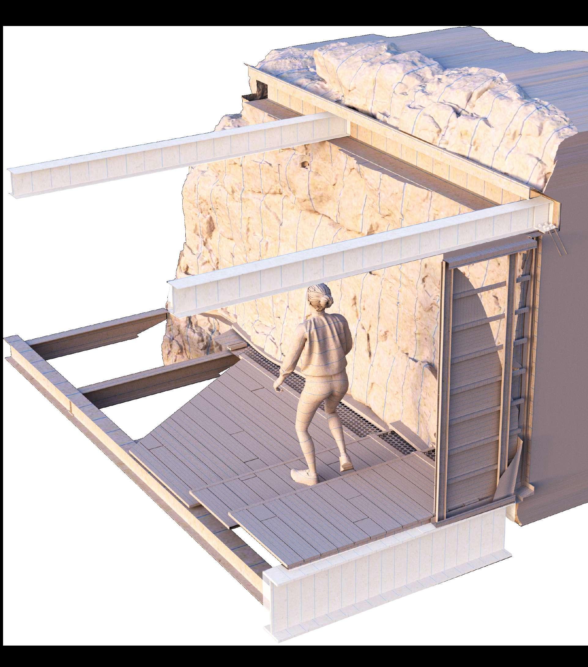
A working deck is the first floor fully assembled to allow workers mobile access between all 3 cores so that they can then assist with directing and assembling the rest of the prefab structure.
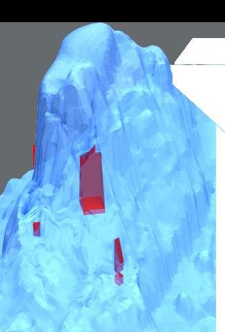
Excavation of the rock begins, allowing the placement of the core, material excess is continuously transferred down the cable crane down to the delivery site 100m south. Approximately 800m3 of rock is excavated.
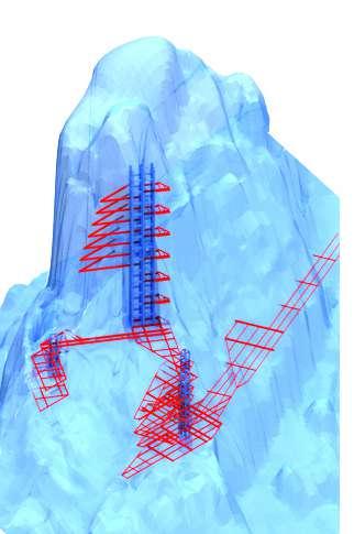
Primary structure is then delivered and assembled. Further detailing of sequence in page 2.01. The size and component assembled are dependant on overall weight and size, page 2.02.
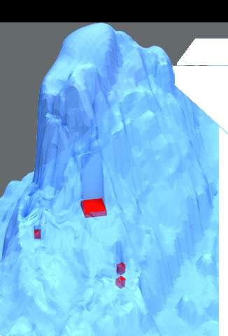
To stabilise the cores, concrete is poured up to 2m deep into the excavated holes. A shallow foundation is sufficient as the rock provides enough stability to anchor the cores.
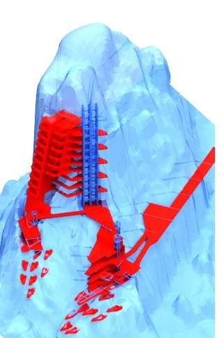
As much of the finishing is pre assembled in compartments so when delivered they can plug into the structural frame. This then means components done in the fit out stage are already achieved earlier on in the process in the controlled environment of the assembly hangar. Certain portions of ETFE are placed prior to the finish assembly for weathering reasons.
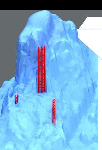
Steel cores are delivered to the site in already pre assembled components to the extent of the size and weight that an air crane can carry, further info 2.01. The tower cores are further stabilised to the rock via anchors placed every other floor.
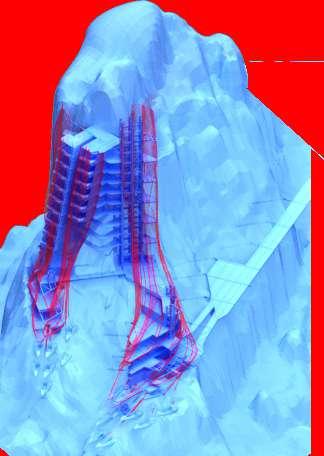
In a similar construction sequence as that of the Eden project, the lightweight skin structure is delivered in components and then attached onto the primary structure. During this sequence the water and air piping is already attached to this structure and hence is installed in parallel.
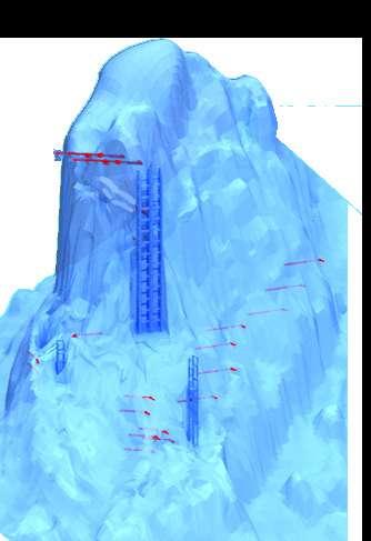
Ground anchors are then inserted into the rock to assist the cores and provide points of which pre assembled components can easily attach onto. An anchoring system is more accurate and structurally viable than drilled slits in the rock. Each ground anchor is fitted with connection plates with which the floors attaches to.
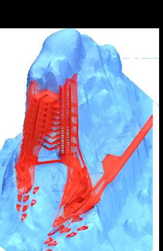
The ETFE pillows are then inserted after to avoid them being pierced during delivery and construction, effectively sealing off the internal rooms. Final fitting of the building constitutes of assembly of elements not apart of the prefab sequencing in this scenario.
PREFAB DELIVERY
The assembly of the prefab elements requires specific sequencing and methodology as to how these elements interact with and use the cliff alongside the anchors plugged into the cliff. Assembly must be quick and straightforward for each element, therefore fast connection joints such as pin joints are essential. Welding is only used in the prefab construction process, on site assembly requires fast fittings.
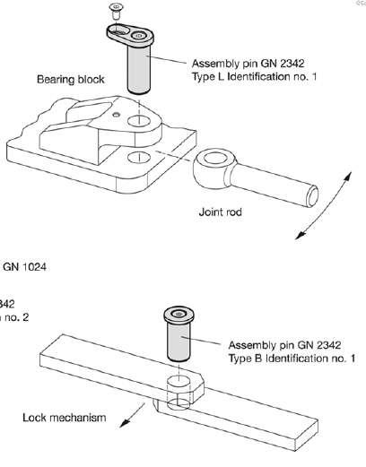
The sequence of construction requires fast and easy connections, pin joints and other quick fitting devices are used where possible to secure the components together as quickly as possible. Complicated assemblies would increase time taken which is infective when using time precious and costly use of the air crane.
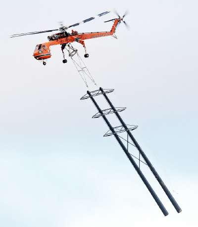
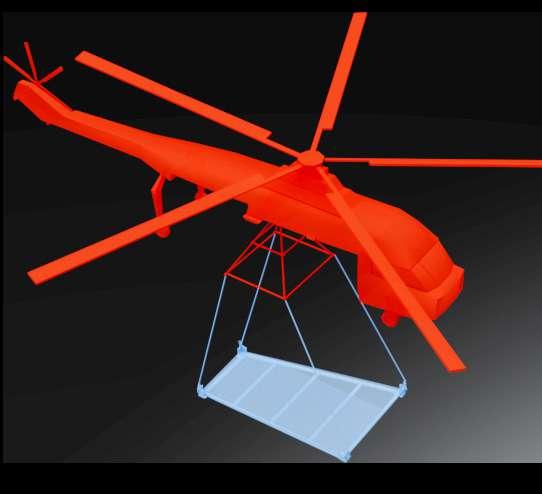
Air cranes are generally used to carry heavy loads to remote locations. The Sikorsky S-64 Air crane is used for heavy duty operations in the delivery of heavy equipment to remote locations. It can carry up to 9,071 kilos per payload, providing a set weight restriction capacity and therefore restriction the size and weight of the prefabricated components.
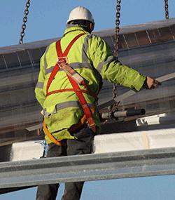
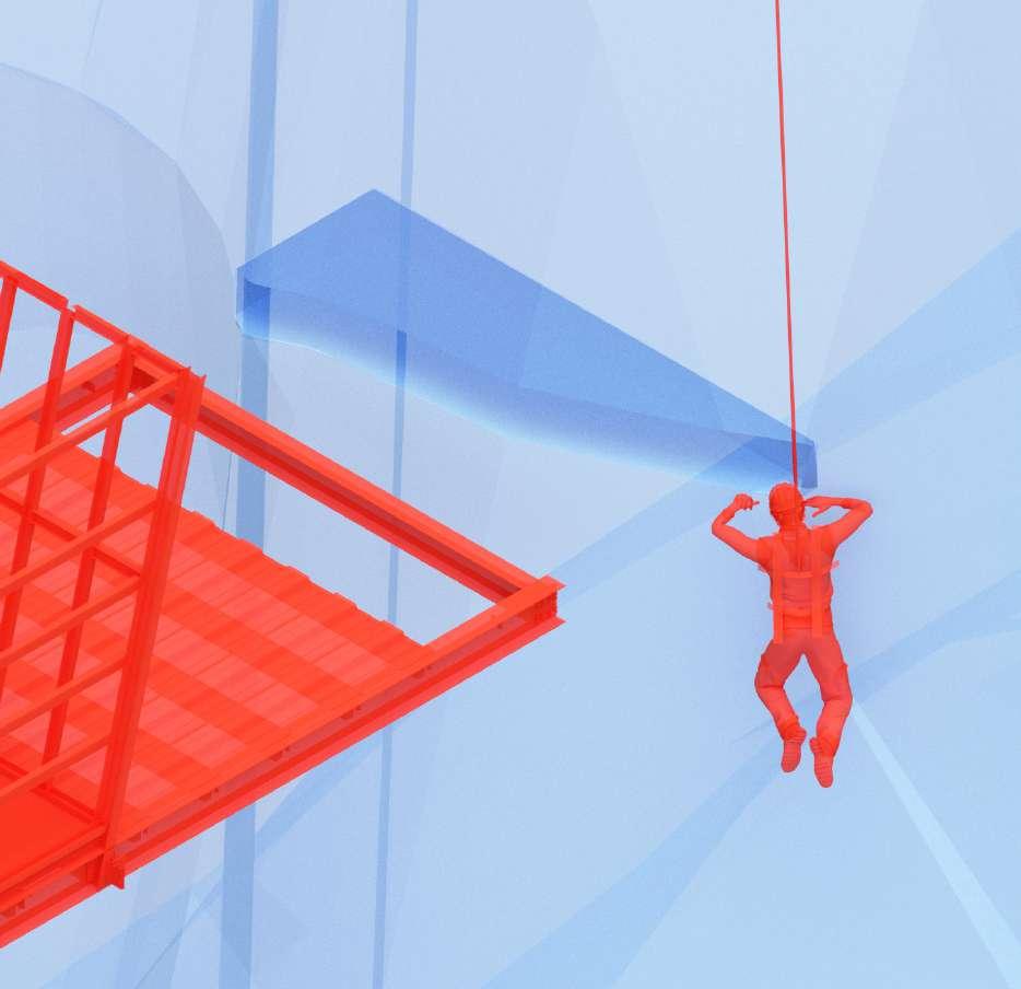
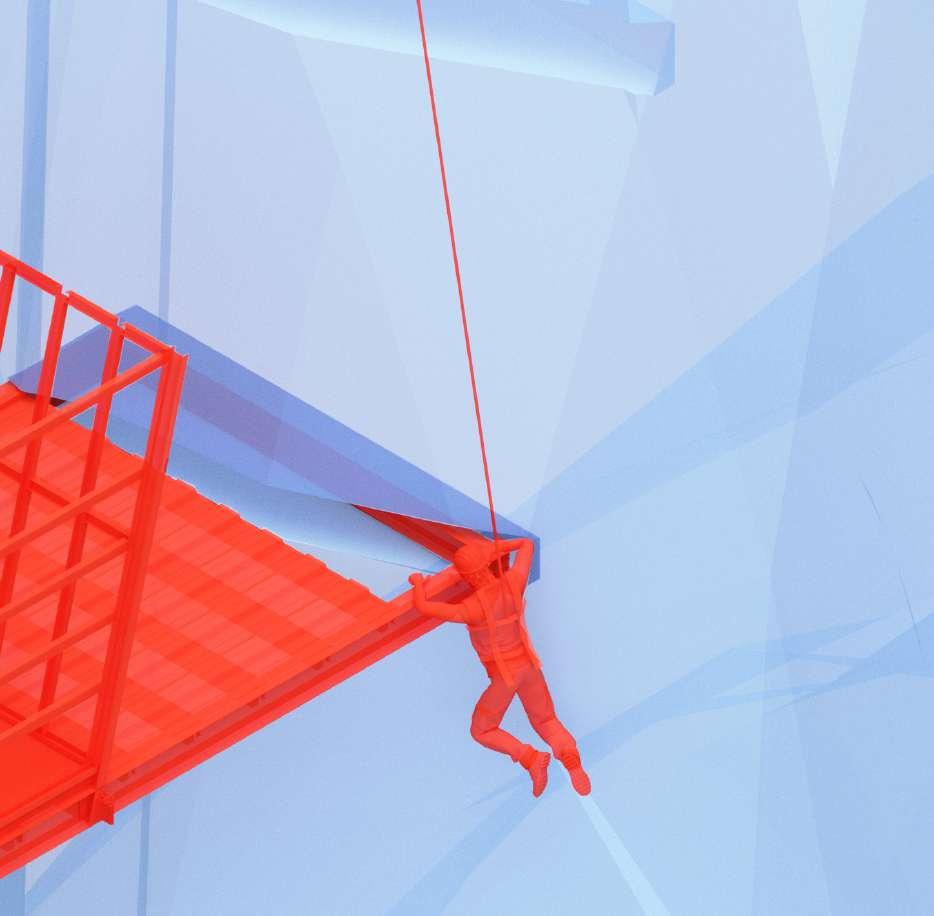
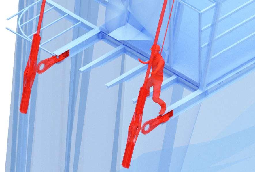
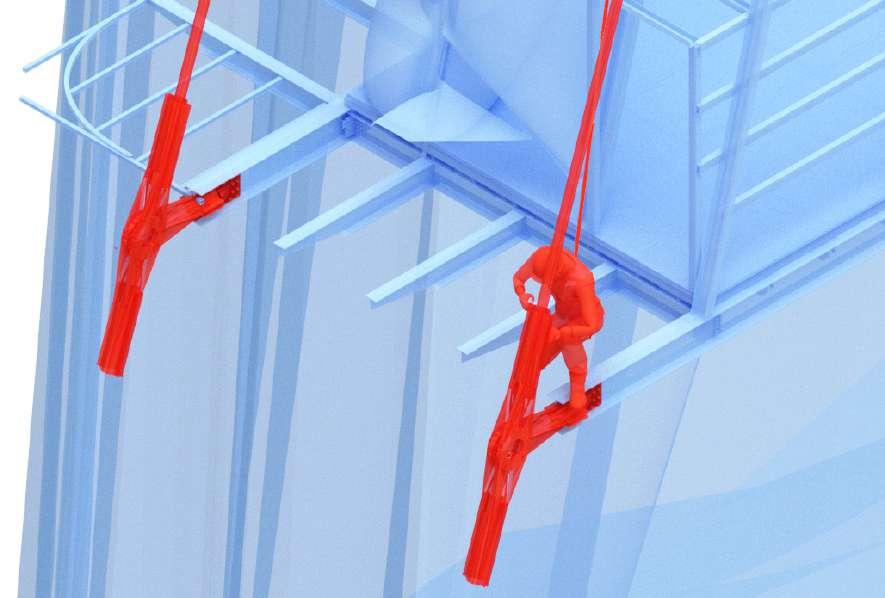
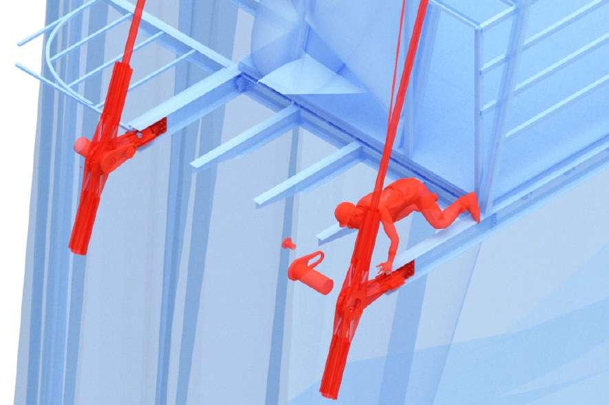
Construction workers working at height use safety harnesses in case of falling but also use hanging harnesses to suspend workers when working in extreme conditions. Health and safety measures are further specified in chapter 4.
FIRE STRATEGY
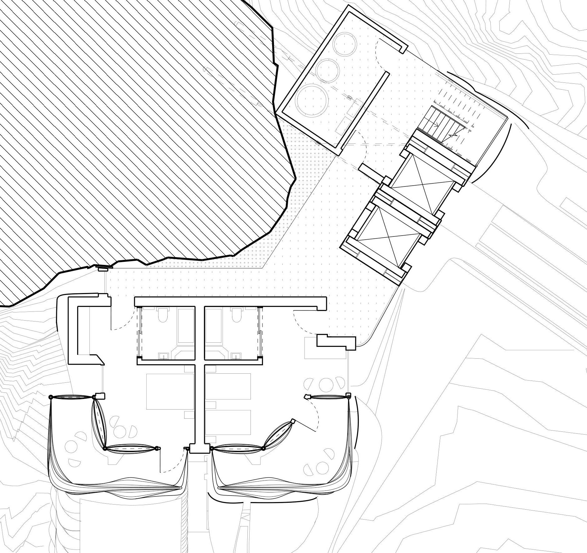
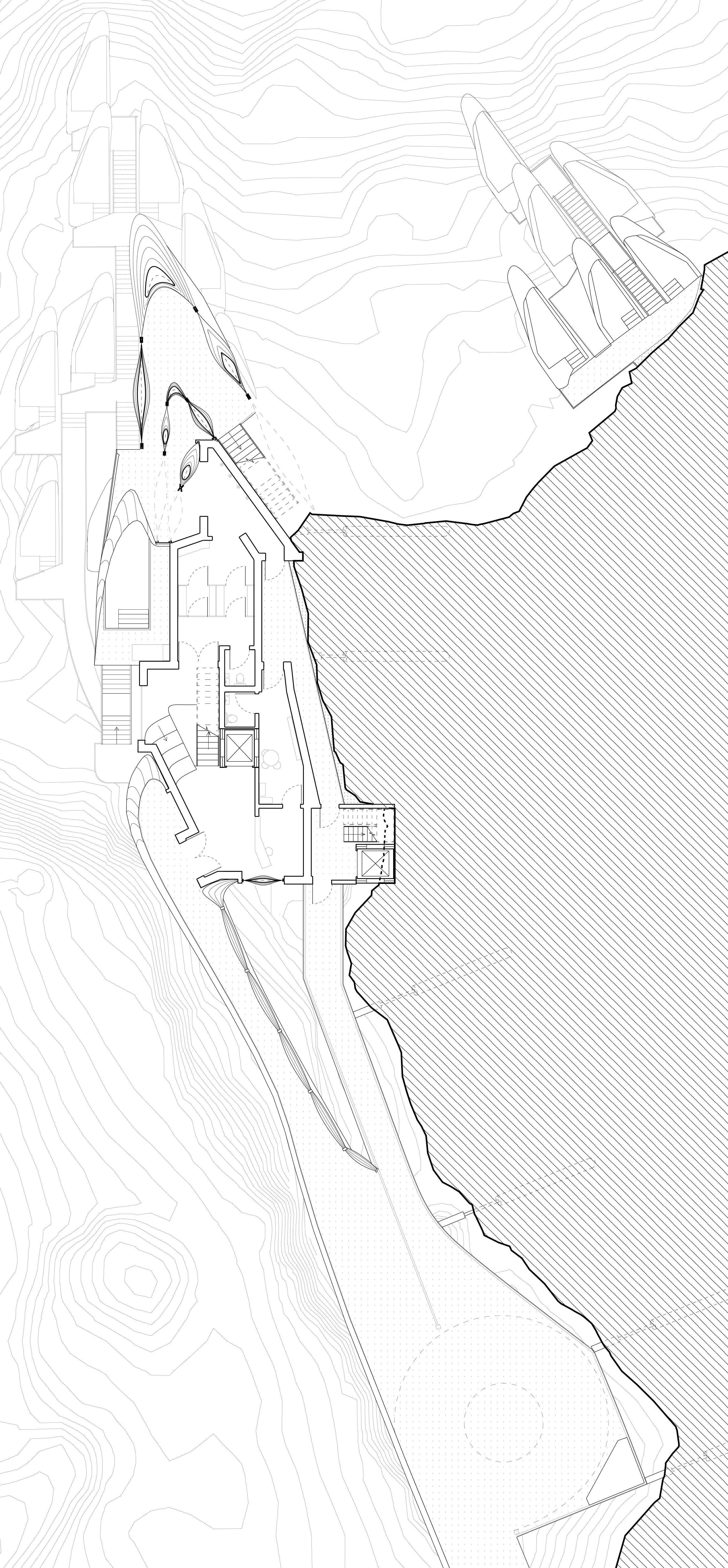
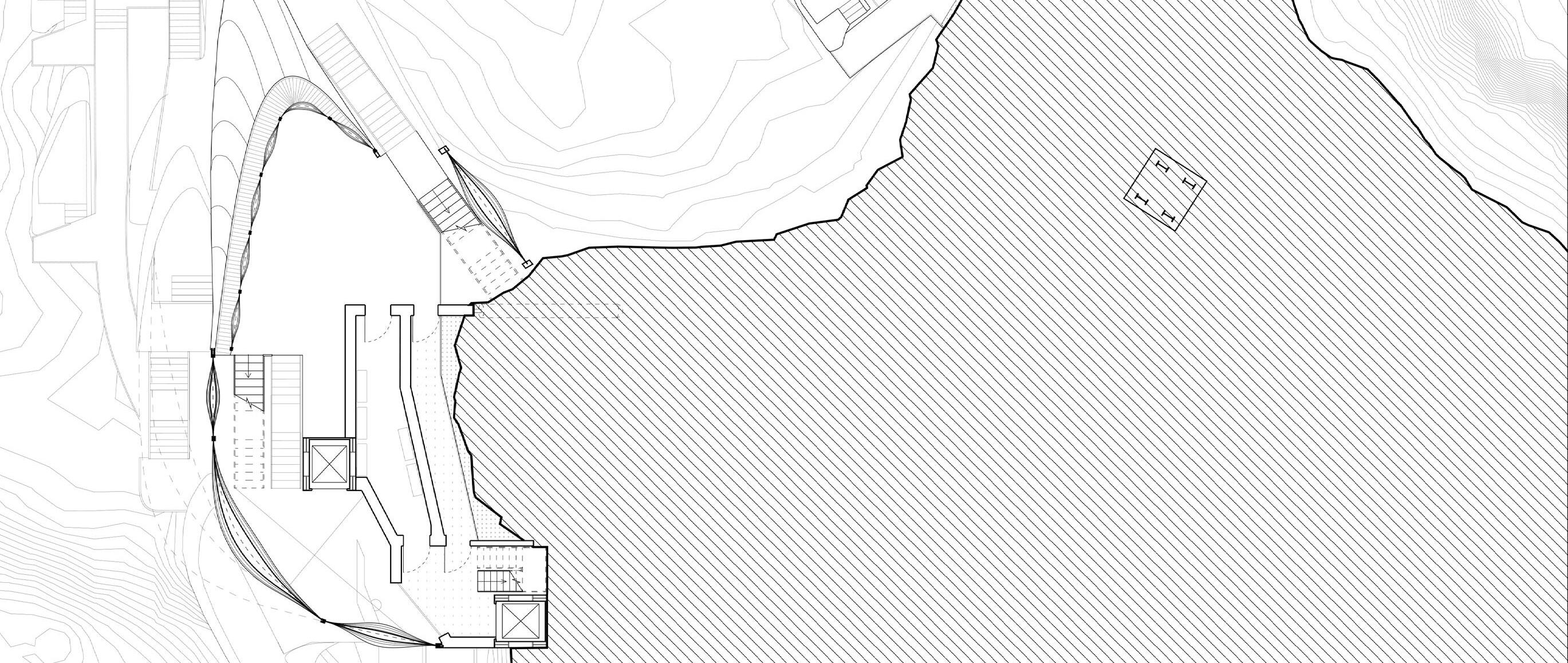
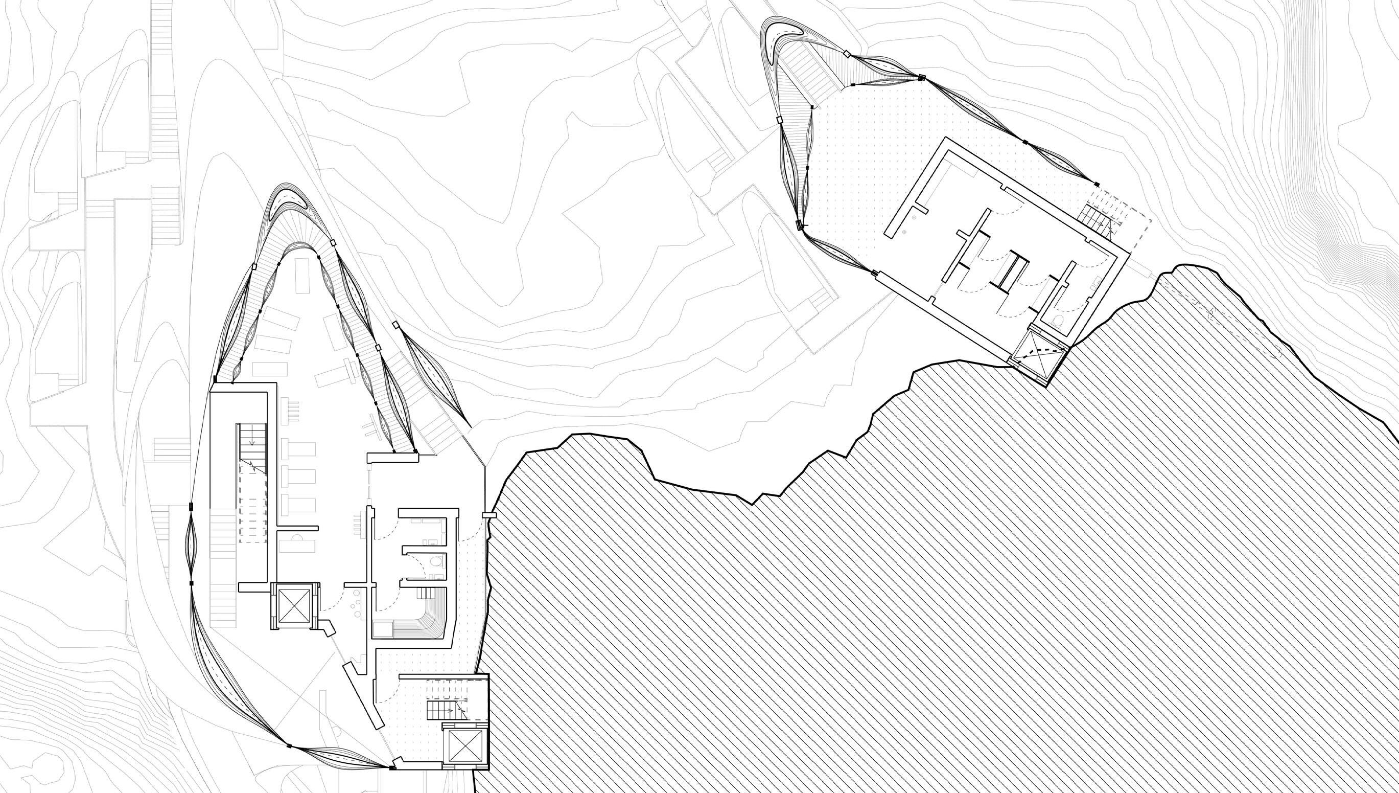
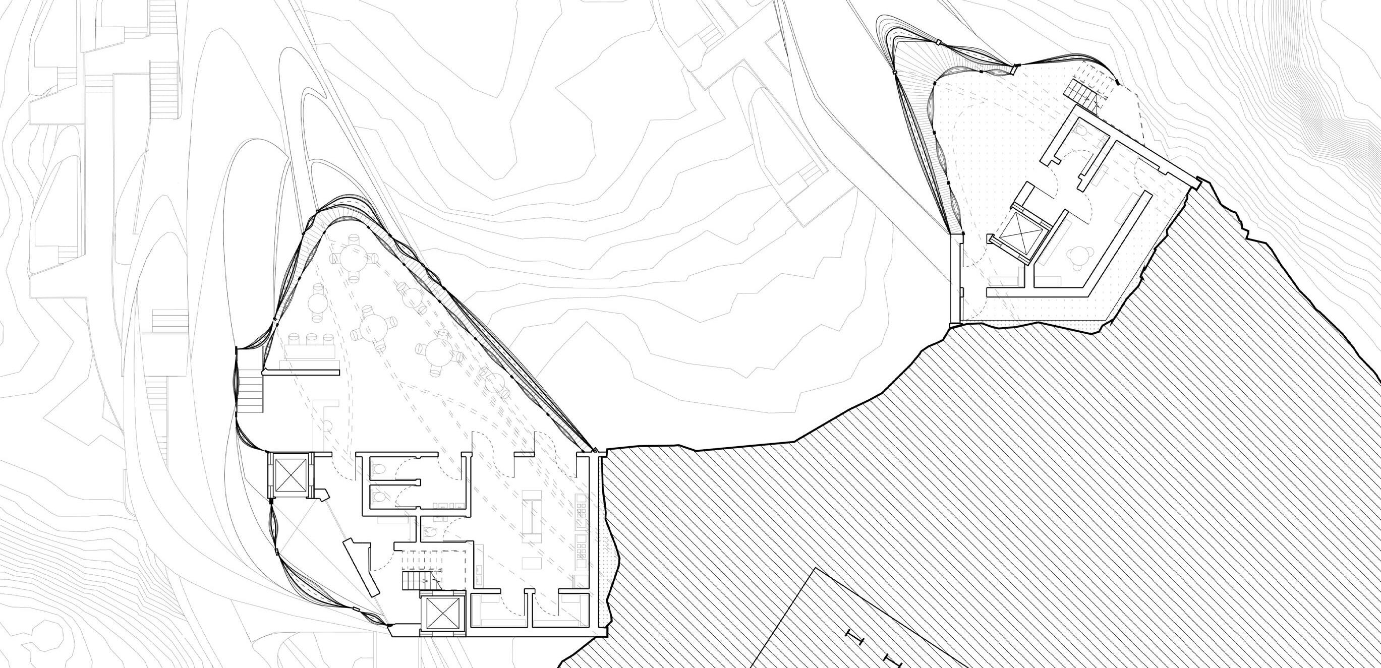
Due to the remote access of the site and only one viable exit from the building onto the main road. The exit strategy leads to one location exit along the cliff. To facilitate the speed of exit, the external unobstructed corridors on the side of the cliff offer direct access to the fire escape stairs which lead out of the building. The use of water pipes along the facade also play a key role in the extinguish and containment of a potential fire as it feeds water into water-sprinklers placed around the building.

PART B REGULATIONS
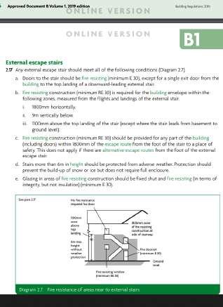
Part B regulations state that high risk areas require a maximum 18 meter escape route, whilst low risk areas require 25. Due to the placement of the unobstructed external cliff corridors on each floor, every major programmatic space has direct access to the fire escape via these corridors. The longest distance to travel in plan is the ground floor, where the building spans 24 m long from each external space. However this area would fall in the range of low risk due to It only accommodating the lobby, pools and changing rooms. Fire extinguishers points are placed around each floor. As per clause 3.8 in Part B Building Regulations. Escape routes require a minimum escape width of 1050 mm.
WATER TANK AND SPRINKLER SYSTEM
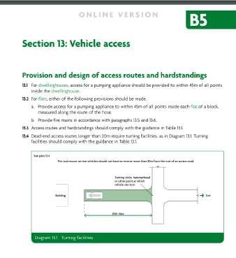
Water tanks span the entire height of the towers and are connected to water pipes used for the distribution of water which can subsequently feed into the sprinkler system. Due to the layout of the skins components and subsequent pipes, water can be delivered to every floor and room to extinguish the fire quickly. Access for a pumping appliance must be within 45m of all points inside, which can be done through linking to the water circulation passed through the entire building.
POTENTIAL FIRE CAUSE
The biggest risk of the cause of a fire would in fact be external, due to the hot temperatures of Tenerife and the abundance of dry bushes, a bush fire could set off. Other potential dangers is the humidity and moisture caused from the cliff and its impact on electronics. The presence of moisture can rapidly increase the current in the circuit, which certain appliances will cause a short circuit as the fuse is blown. However, if a fuse is not present, then the wire will heat up and a fire could start. With aspects such as the inflatable panels and other wiring, these are placed away from the cliff edge cavities to avoid the build up of moisture gathered in these spaces.
FIRE WARNING
Each space contains fire alarms that can be heard both inside and outside of the building. When activated exists will become highlighted to display to occupants the fastest way to exit the room and floor which is via the cavity corridors along the cliff.
MATERIALITY AND FIRE RESISTANCE
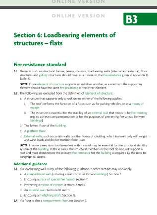
The main material finishing used in the building are both fireproof, both ETFE and the rock cladding are non flammable. Wooden decking is used on the exterior but located next to the pools which would leave the deck constantly wet from use.
NATURAL SMOKE OUTLETS
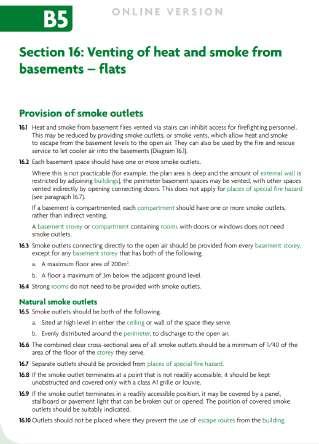
Along the perimeter of each floor there is a 1m gap between the floor plate and the ETFE external skin. This void travels the entire building and is usually used as part of the ventilation strategy. In the case of a fire, smoke would travel through this void on the outer perimeter and travel up to the top ETFE ceiling where it escapes.
EXTERNAL
The
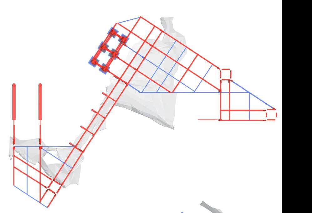
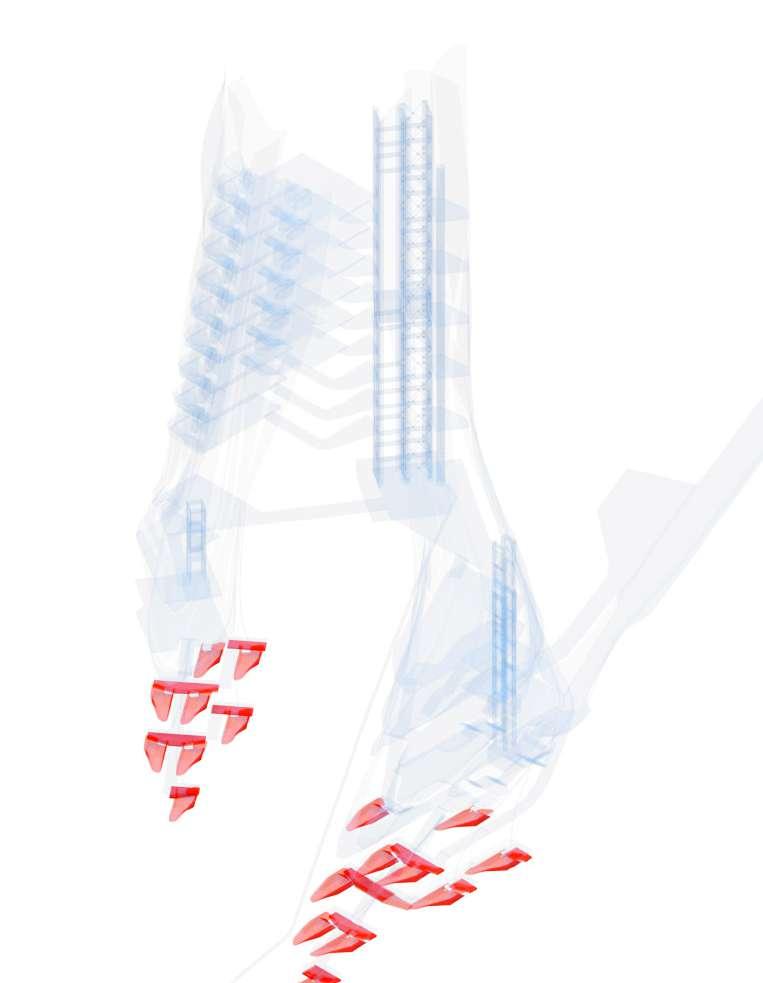
The prefab elements to be delivered are designed based off of restrictions of weight, size, accessibility and self supporting sequencing Certain elements are not prefab due to accessibility of the air crane and allowing for tolerance gaps during assembly that can range +/- 10 mm. To reduce the error of tolerance in relation to the rock excavation, precisely placed and measured anchors allow for a more accurate connection. Any elements resting in the rock are drilled out larger than needed to prevent tolerance issues in time essential assembly. During construction it is essential that each stage can support itself, If there was an issue with one of the components and that portion could not be assembled. A series of alternative sequencing strategies would be in place for every situation. So if one part could not connect, a different portion of the design would begin assembly whilst the error is rectified. However to minimise this risk, pieces are tested in assembly before hand.
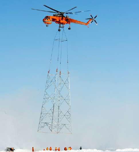
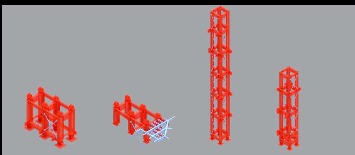

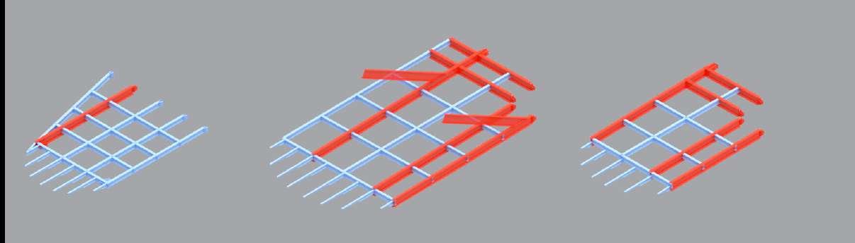
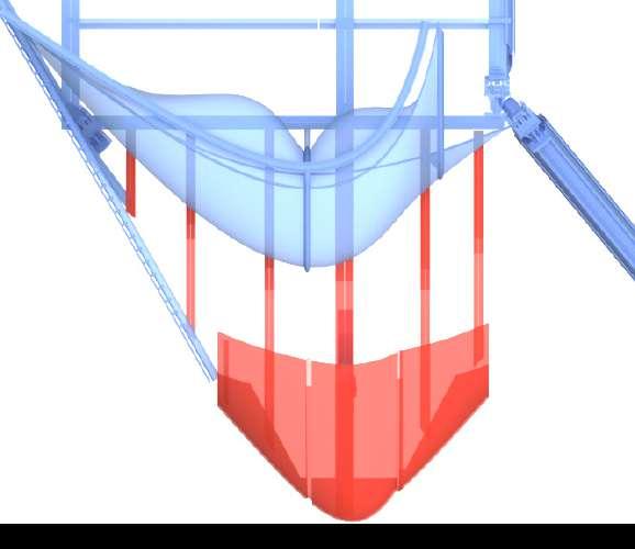
The skycrane can carry a total load of 9071 kg, however the prefab components do not use the maximum capacity of the sky crane. If an element is too heavy, workers cannot place it as quickly as needed and it is more difficult too operate during this time crucial assembly. Also size cannot be too large, otherwise elements cannot fit into some of the tighter areas.
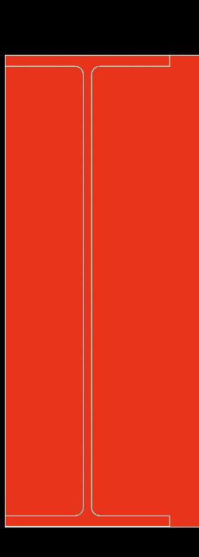
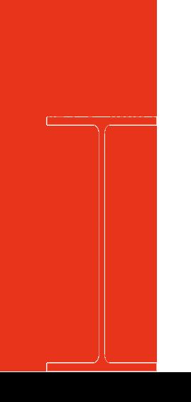
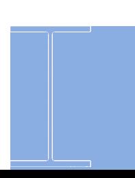
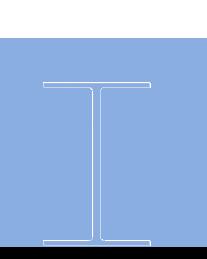
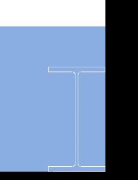
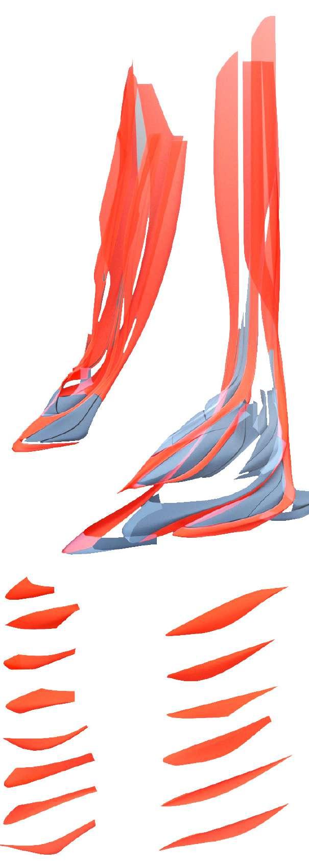
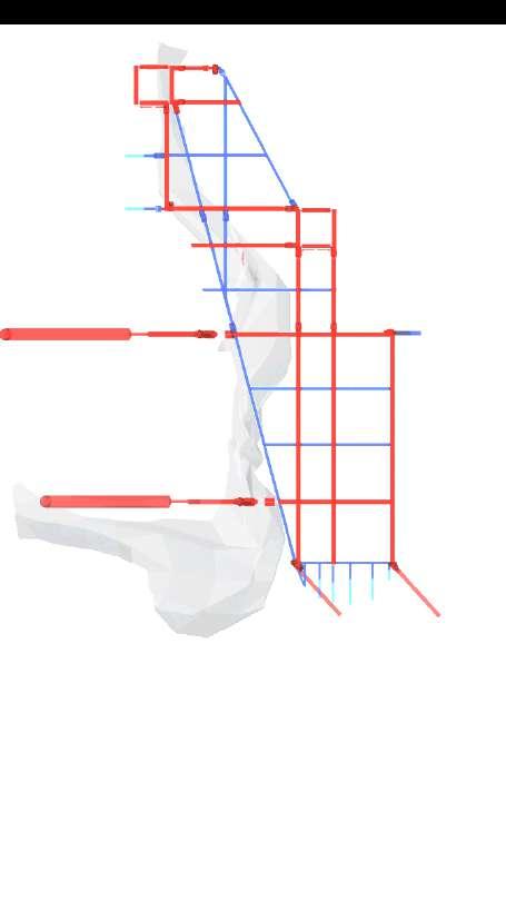
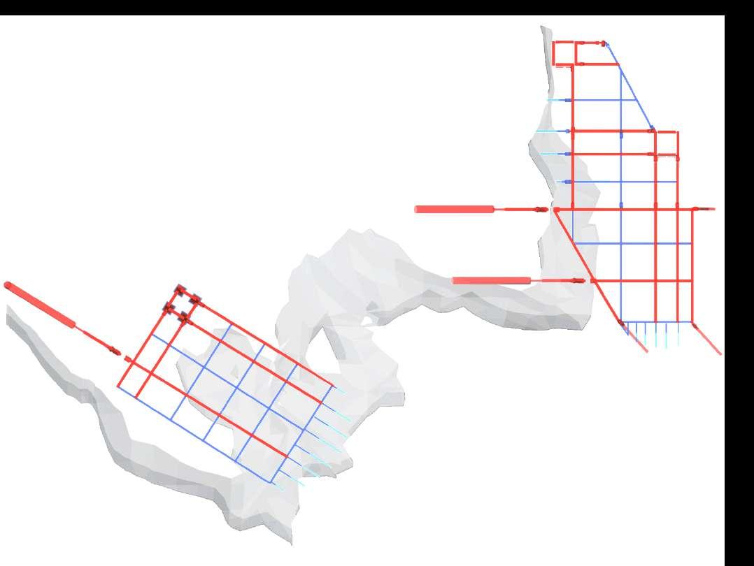
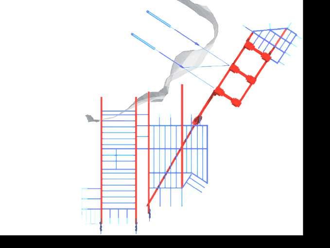
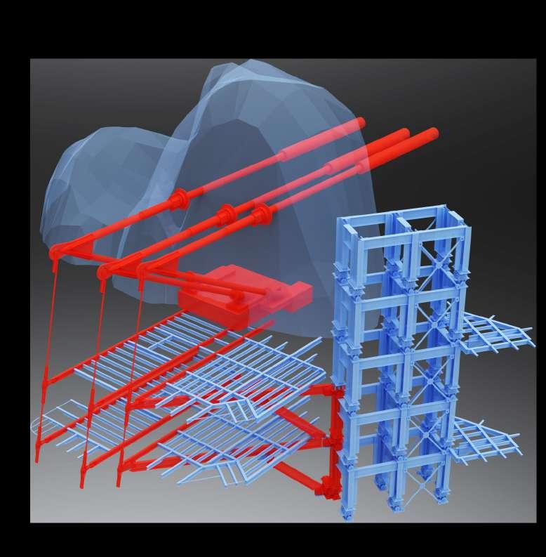
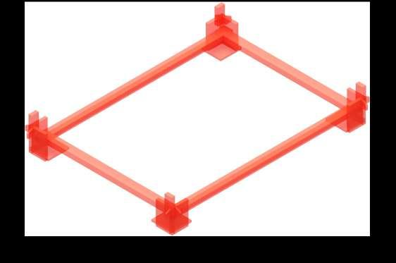
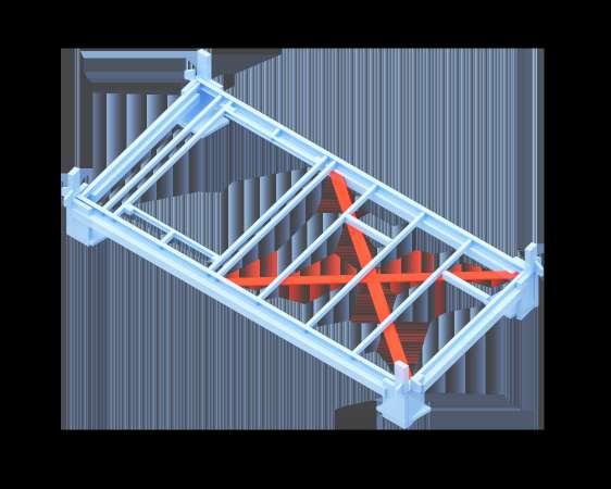
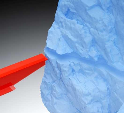
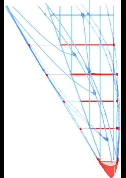
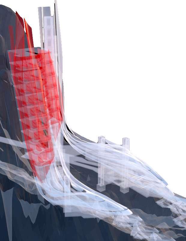
beams shown are split between primary elements in red and secondary in blue. Primary elements always connect to either the core or an anchor once assembled. Sizes and weight for the I beams were sourced from BRITISH STEEL so as to be able to calculate the overall weight of the prefab structure. Sizes of beams used vary depending on cantilevering.
7 m x 52 kg = 364 kg
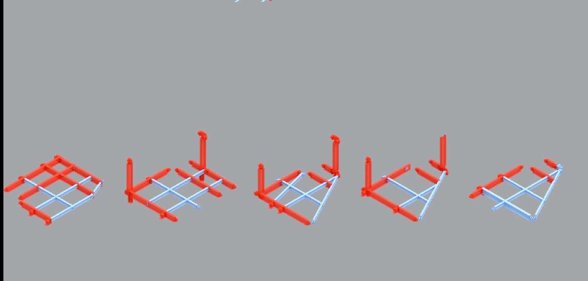


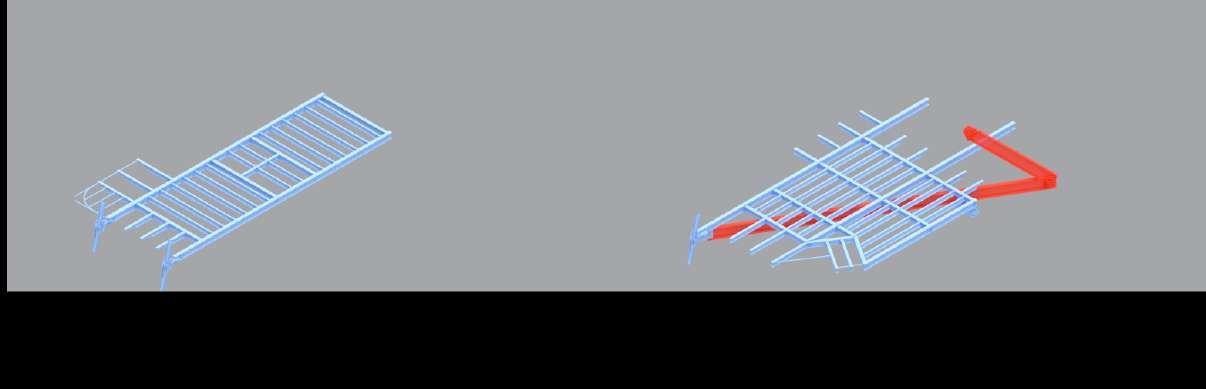

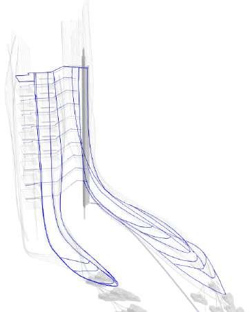
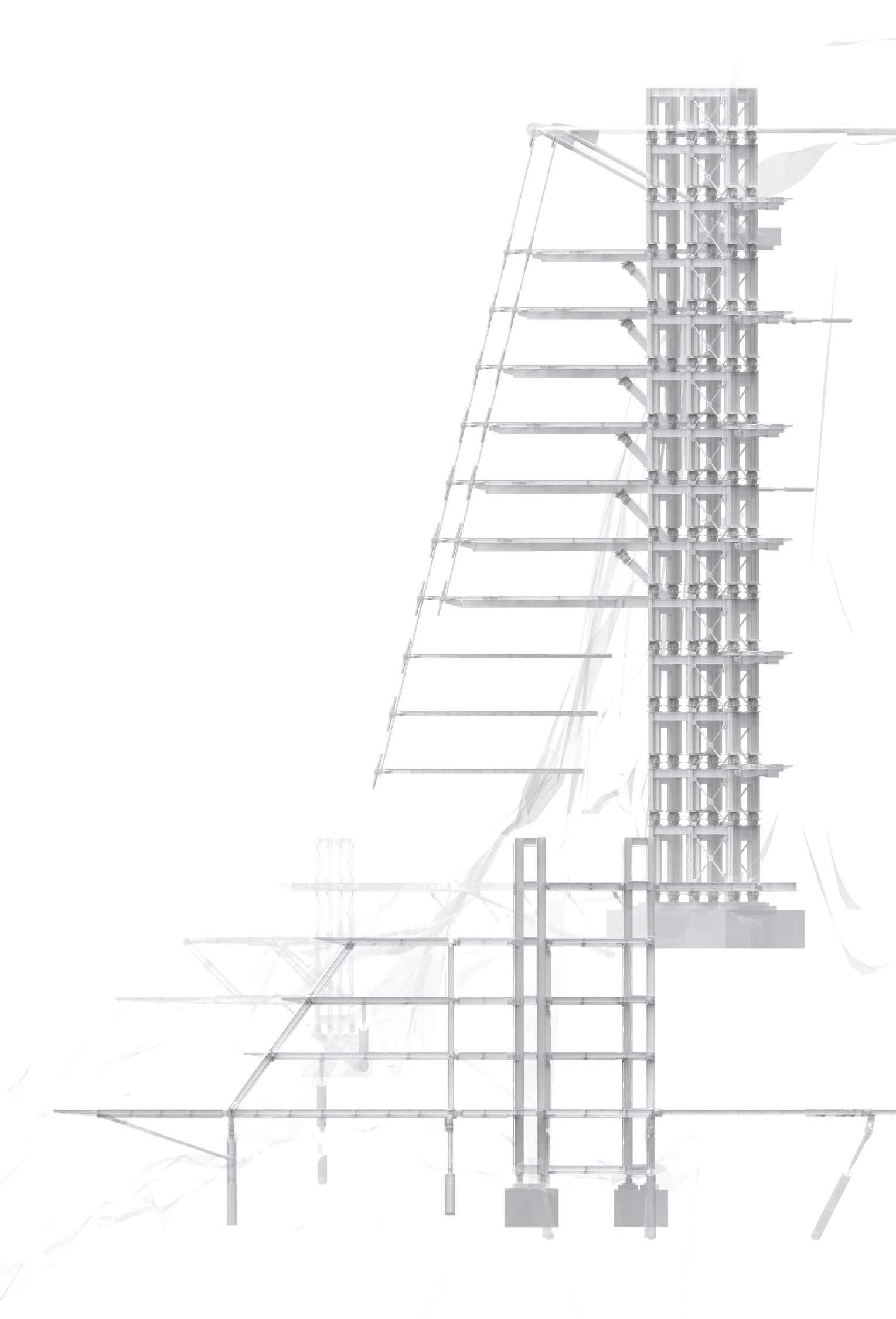
The structural approach to this project uses two main methods, the first being that of spanning floors between cores and anchors set into the mountain to deal with the vertical terrain. The second strategy, used in the hotel towers is the use of tensile suspension, where each floor end is upheld by a 15m deep anchor which operates in a similar manner to systems used in cable stayed bridges. This system is used due to the sequencing of assembly needed from the steeper verticality of the site in that area.
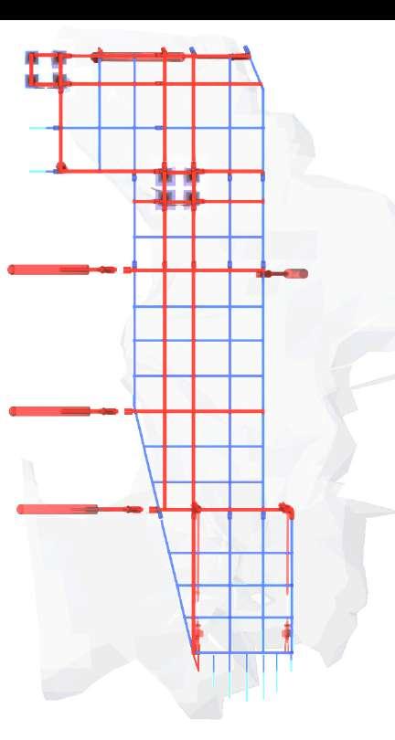
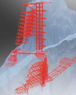
One of the most unique elements of the devised system is using the rock to bare weight, by inserting anchors into the cliff which then go on to attach to beams during the prefab construction sequence. The use of the cliff can also be used without anchors in areas of less stress, a slit can be simply excavated and the beam rests within. However this beam cannot go onto help with any cantilevering. Larger beams are used to allow cantilevering, a maximum 450mm beams can be used due to the height per room, therefore limiting any cantilevering to around 2 to 3m when using these beams. ‘Doubling up’ these primary I beams allows the cantilever to go slightly further then the standard 1 to 5 proportion.
The anchor system is also used in a different manner at the top of the tower, where larger anchors operate on a hanging system, where floors below hang from steel cables. This is crucial to the sequence of assembly.
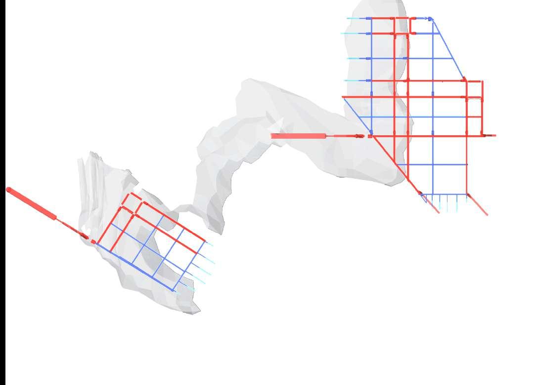
CORES A UB_457x152 beam always connects the anchors and cores, the 2m distance from primary elements allows a ‘doubling up‘ effect to help with any cantilevering elements. The hotel room combine a use of a tensile hanging system at the end of each floor, whilst also resting on excavated slits in the rock. This is also supported with the UB_838x292 I beams in the room closest to the
15
Due to the verticality of this area of the cliff, an alternate strategy was devised. A hanging tensile system is used where 15 metre deep anchors combined with a strut and concrete bearing plate enact a backs pan, directing the forces into the mountain. The strategy works similarly to that used in a cable stayed bridge or a Mammoet crane. This strategy of hooking the end of each floor plate allows for the sequencing of each hotel prefab floor to take
3
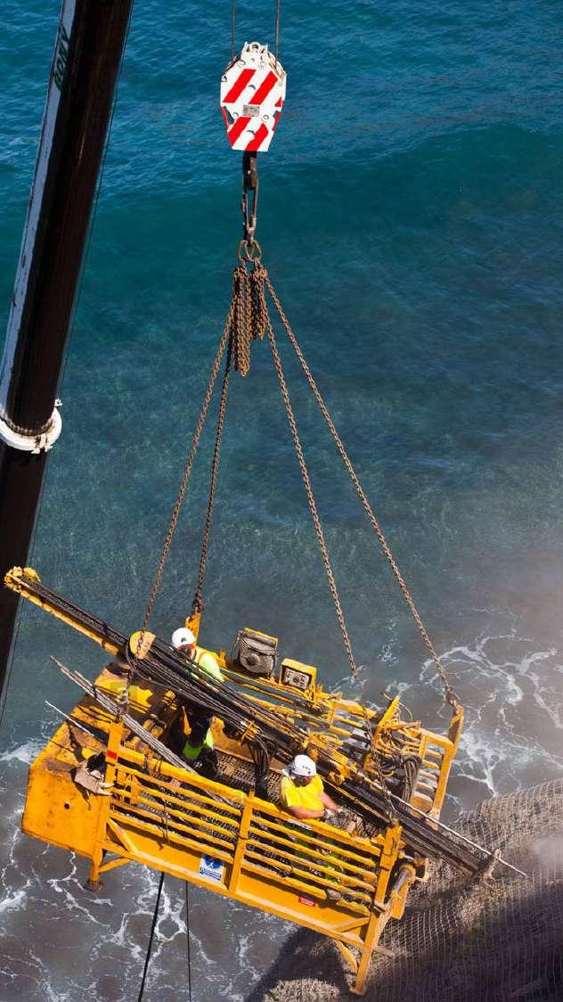
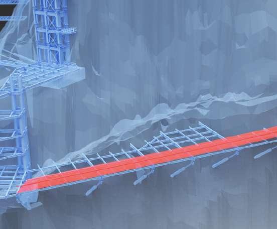
The grounding of the structure into the cliff will be done through the use of ground anchors which will be placed into the rock and act as one of the primary elements upon which the floor plates will rest on. Although this process is usually done on ground level with the drill attached to a truck, it is also possible to us more portable equipment that can be attached to more versatile frames such as a crane as seen below.
GROUND ANCHORING
Ground anchors are usually used in basement construction and large excavations, due to its minimal horizontal deflections minimal soil disturbance during installation the anchors can be stressed to an exact holding capacity. It is a proven versatile technique for anchoring a wide range of structures into place. Anchors come in sizes up to 70 m in length, with a capacity of more than 3,000 kN.The anchors are lightweight, corrosion-resistant and can be installed either by hand or using portable equipment. An anchors life expectancy is based on the corrovisity of the soil rock that is being drilled into. The anchor comes in a range of materials, notably steel bar, GRP, aluminium alloy and hard anodised aluminium alloy. In this case steel bar was used. For permanent anchors a corrosion resistant finish must be applied. The performance of the anchor is dependant on factors such as the shear angle of the rock, size of anchor, depth of installation and of course the load applied on the anchor.
borehole is first drilled to the correct diameter and length. The temporary crane grounded at the top of the cliff manoeuvres the drill to the right location to be excavated.
FOCUS: PREFAB CONSTRUCTION OF FLOORS AND WALLS
Due to the remote nature of the site, as many elements are pre fabricated as possible. All floor and walls are fully assembled in a hanger in the city 4km away, a hanger near the quarry is most ideal as any deliveries from the ship from external shipping would travel a minimal distance. Elements could even be picked off of the boat if needed by the air crane.
STEEL JIG
PREFAB
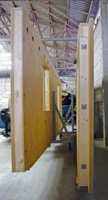
Walls and floors are pre assembled in a hanger in Santa Cruz quarry. The entire wall fit out is assembled due to minimising the amount of manual work on site due to the difficulty of the terrain and the need for a quick assembly on site. Each wall contains a series of connecting systems to allow each wall to essentially clip onto each other and hold in place. Prefab internal walls can only be inserted on site once if weather protection from rain has been placed above. This can either be temporary or permanent as part of a staged assembly of the ETFE skin. Materials are delivered to the quarry site via boat and then pre assembled in the city 4.5 km away from the site. Therefore the air crane only needs to travel a short distances and can make multiple deliveries quickly, saving on fuel and allowing for the air crane to be rented for a shorter amount of time therefore reducing cost.
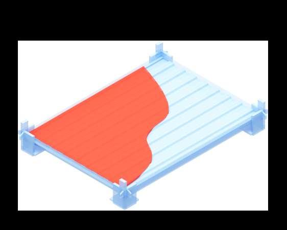
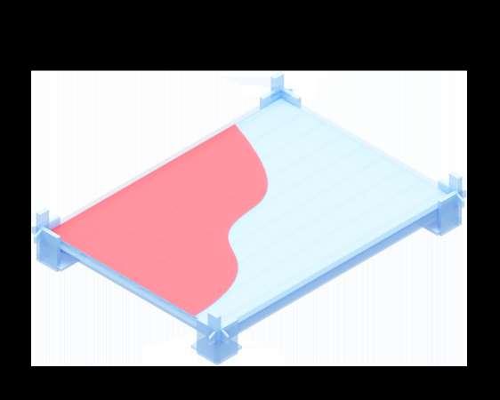
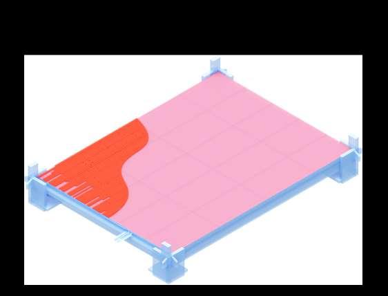
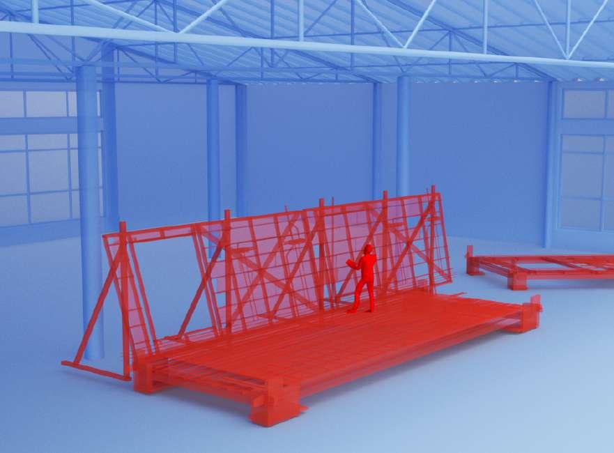
An adaptable steel jig is dimensioned to the size of the required floor slab to make sure each placed layer is set to the correct dimension. The size of each floor will be as wide or as large as possible to avoid the amount of assembly. However size and weight must be taken into account so that each fragment can be easily moved by workers. These jigs can then be stacked and transported to site.
CONCRETE AND STEEL DECKING
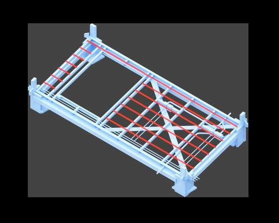
Steel decking is placed on the jig, additional beams can be inserted below to support multiple steel decks and simulate I beams. The size of each prefab floor must obviously be larger than the distance between beams.
A membrane is fitted along the exterior of the jig temporally whilst concrete is poured and dries in the steel deck to prevent leaking.
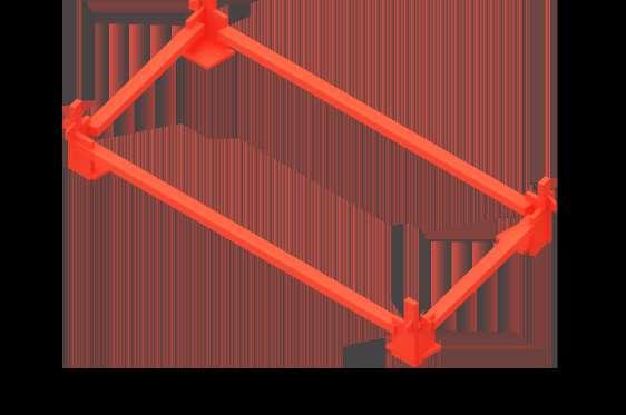
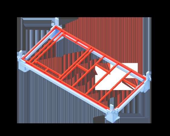
DAMP PROOF MEMBRANE
A damp proof membrane is placed on top of the concrete, the size of each of prefab floor is as large as possible to allow as wide a span of the sheets to be used as possible, so as to prevent leaking between overlapping layers if there were too many small fragments.
SHORT DELIVERY
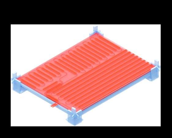
COOLING FLOOR PIPES
Floor pipes are placed within 50mm insulation and held via aluminium diffusion plates, these pipes must link up with every prefab floor component so the pipe must protrude from each floor to allow workers to access the pipe and successfully link the pipes together. The cool water originates from the air source heat pump strategy. The pattern of the pipes takes on the form of any internal wall placings
ACOUSTIC LINING
To avoid echoes, acoustic linings are placed between the dry screed and floor pipes
DRY SCREED
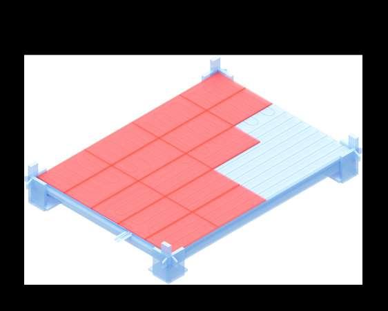
1200x 600 mm dry screed panels are pre fitted as part of the pre assembly.
ADAPTABLE JIG
The jigs can be adapted to take the from of non-rectangular forms such as diamonds to allow slanted walls to be constructed.
STUDS
Stud walls are assembled via the form of the jig used. Not all walls are rectangular, but rather some are slanted, such a the hotel rooms which must take the angle of the cliff in order to stack up correctly. Therefore it is essential particular angled cuts and precise work are done in the assembly hangar.
GROUT AND STONE DECKING
Grout is then applied to allow the stone decking to be sealed to the floor. The stone decking finish contains a non regular pattern so as to avoid a visible rectangular pattern of the prefab floor, certain panels along the edge are left out and only inserted once all the floors are placed.
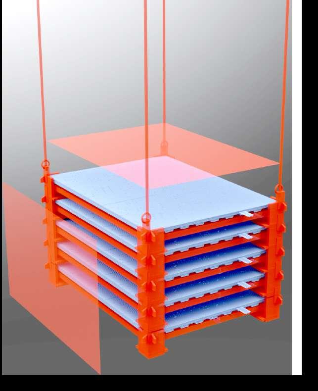
STACKING AND TRANSPORT
BRACING
Due to the angled nature of some of the rooms, additional bracing is used. Flat strap bracing screw fixed to the wall studs.
PIPES AND ELECTRICAL WIRING
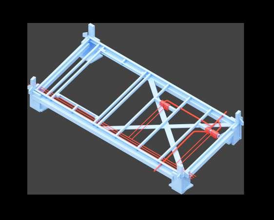
Pipes and electrical wiring are included within the prefab assembly to be connected and assembled once installed.
The pre assembled elements are still confined to either walls or floors and not fully fitted rooms, the reason for this is for ease of delivery via stacking, where more elements can be delivered at a time. As well as assembly on site, too large pre assembled elements of walls and floors would be difficult to place in position with the fully assembled structure already in place. During transport, a protective film is placed over each element to avoid damage during assembly, it is then peeled off as part of the final finishing process.
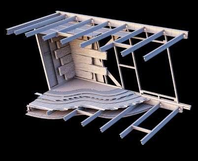
CARRIER AND HANGER RAIL
Carrier rails are attached onto the studs
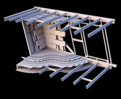
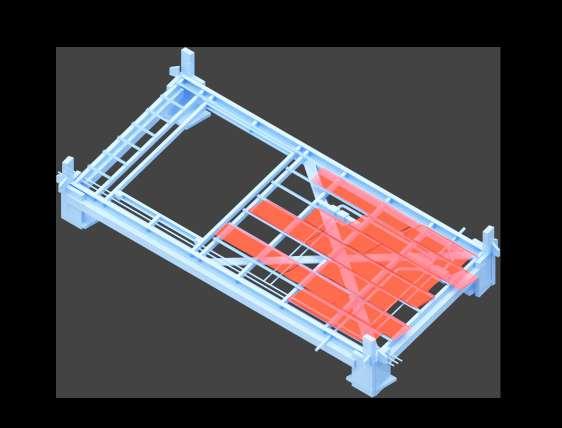
STONE PANELS
Lightweight stone sheets, recycled from the excavation process are bonded to cement carrier board to make the interior panels. These are attached to hanger rails which can slid onto the carrier rails attached to the studs.
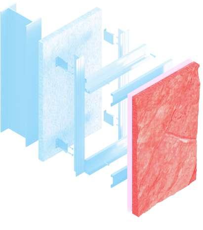
Its important that given the fact that the elements are large prefab components, that this method does not affect the aesthetic visuals of the design. Therefore to avoid situations of a square like stacking pattern of the panels. There is additional finishing that is required once the prefab components are installed.
Prefab walls and floors are delivered and installed on site via two main methods. Air crane is only used where absolutely necessary for elements of significant weight so therefore the heavier and larger floors are delivered via air crane. Whereas walls, being more lightweight, can be operated and moved around the site manually.
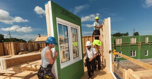
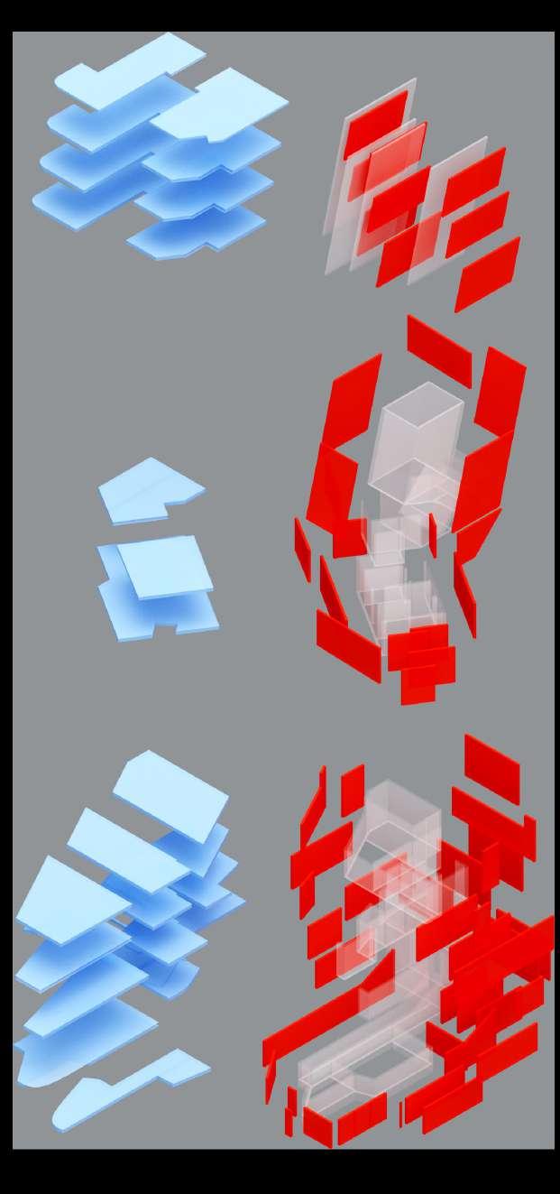
Floors are split up based on the requirement of the delivery process. Meaning, to take into account how they can be fitted into a space which might already have columns or cable which could obstruct. The elements are split so they are small enough to fit through.
The walls being of a smaller portion and more lightweight due to not containing the heavy concrete in the floors are more versatile in their ability to be moved around the site.
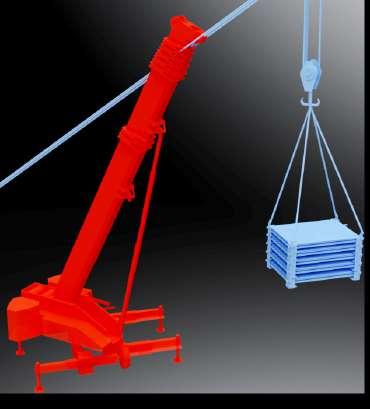
Due to the smaller size of the walls and reduced weight, these elements can be moved around the site by workers. Therefore do not rely on the air crane as means of transportation. They can instead be delivered via cable cranes and delivered to a covered area of the site from which workers can then distribute them around the site.
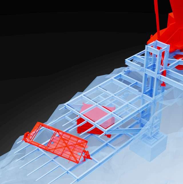
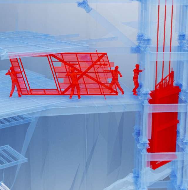
- Assembly: If there are visual issues in the assembly between the walls and floors, skirting is applied above the joints to cover any imperfections.
-Panels: Due to the reuse of the rock for the panels, the mass of the excavated rock outweighs the mass of the number of panels produced. So spares will be made in case of damage in assembly.
- Size: wall sizes must be of a weight and size that a four man team can operate and move, so under five metres in length
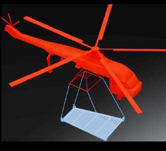
The air crane deliver the heavy floor slabs due to the fact they cannot be easily moved around site manually with machinery and are too heavy for workers. Once in the air crane is positioned a team can effectively withdraw a plate quickly, install it and be ready for the next delivery of the air crane before it returns with the next floor. There are different systems in place for the tower delivery and the lower part of the building.
Temporary panels are placed on the structure to protect the walls from any rain (although rain in Tenerife is rare). Once derived the worker can remove a wall and carry it to the required destination. These elements are derived as close to the area of assembly as possible to minimise the carrying time by the workers. The walls were purposefully designed with very thin panels so as to reduce its weight during delivery and transportation.
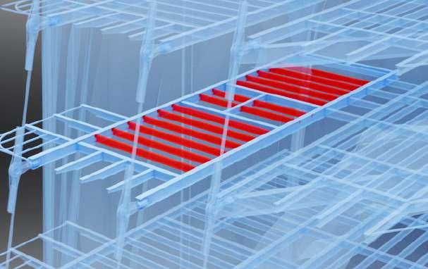
Purlins in the hotel slabs were pre installed as part of the structure sequencing, partially because the floor plates at this height require to be as pre fitted as possible due to the additional difficulty of work and access at this height.
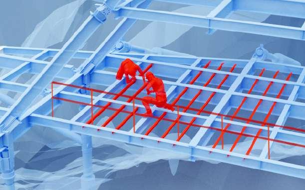
The dimensions of the walls and the core were coordinated together so that the cores were large enough to allow the prefab walls and any equipment to be pullied up, removed and then placed and allocated in the required floor and area.
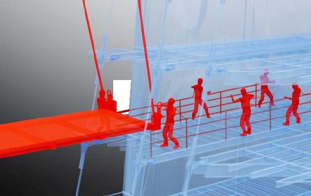
The size of the prefab floors themselves are confined to the maximum width between each cable and column. Elements protruding such as the balcony must be assembled separately. However this is not an issue as it is an exterior element.
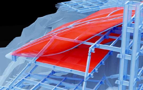
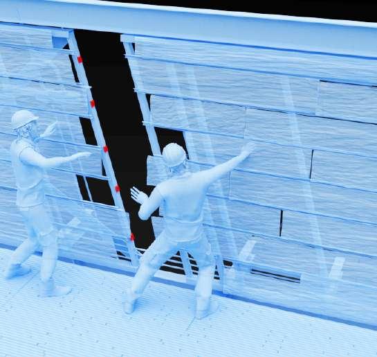
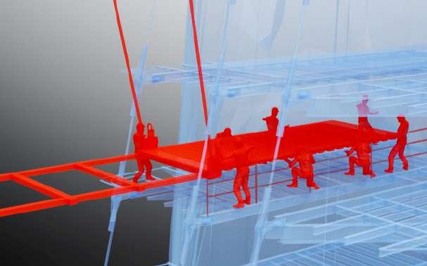
The support mechanism contains a quick unhinge system, which when rotated allows the worker to lower part of the device and controllably slide the floor out. The angle of the mountain is beneficial to the delivery via crane whereas a purely vertical angle would not be possible for this operation.
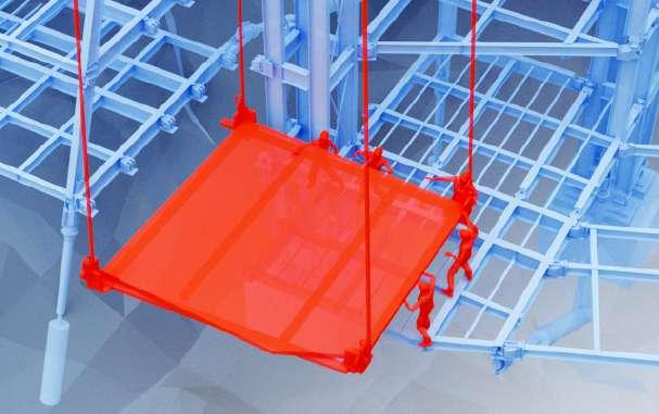
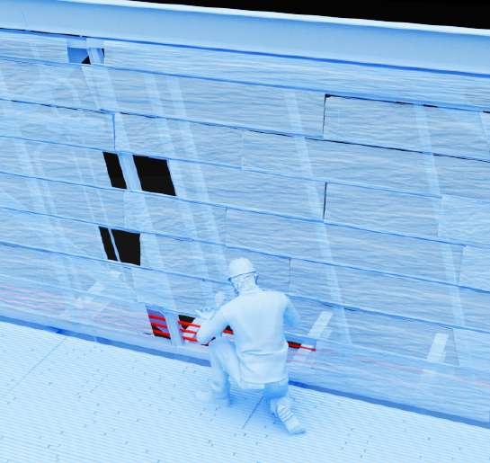
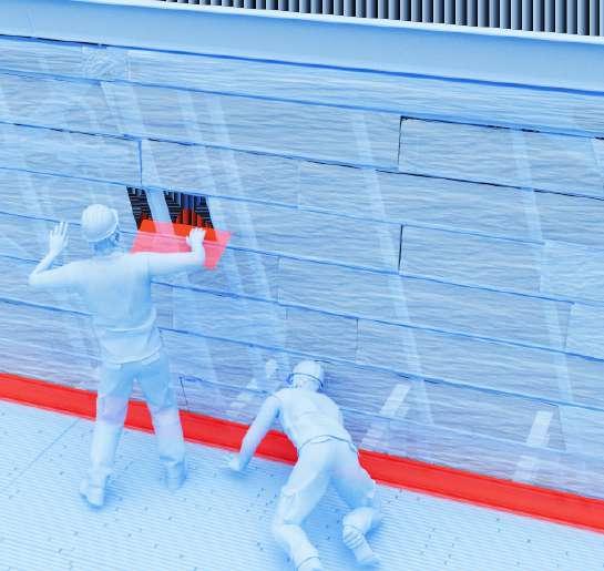
Slide in connecting joints are used that easily allow the walls to be slid into one another and fastened in place.
Panels are left out to allow worker
CABLE CRANE_WALLS
CONNECTING WALLS
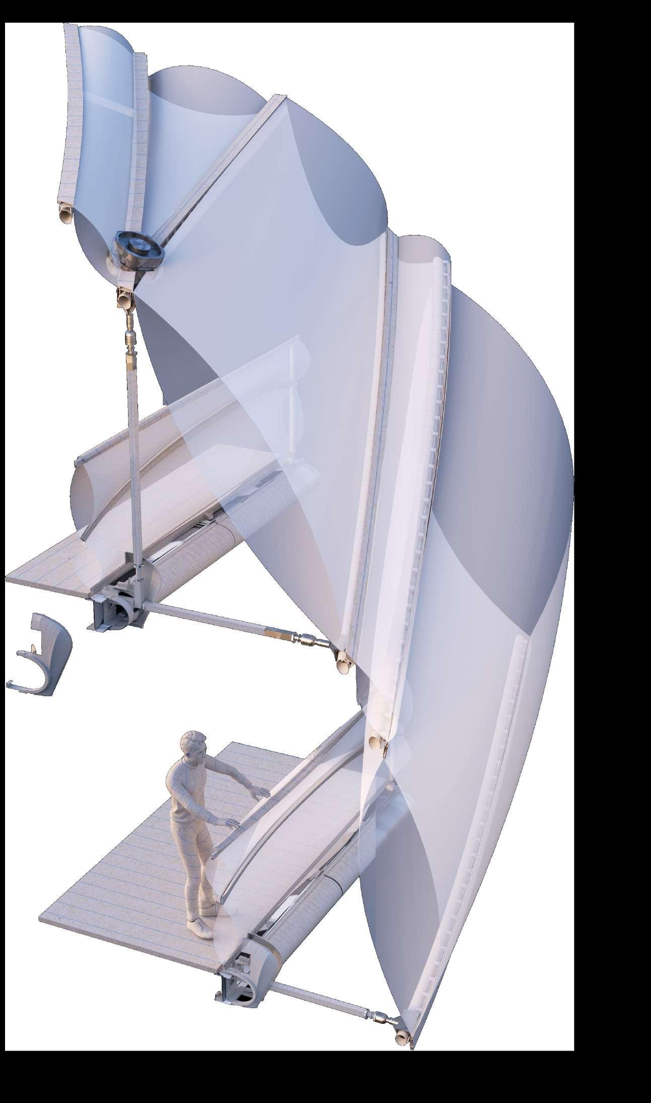
2.07 FOCUS: MERGING LANGUAGE OF PRIMARY STRUCTURE AND ETFE
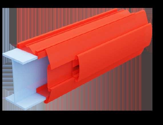
All structural elements must have an envelope finish placed on them such as profiles to fit the language of the ETFE aesthetic-applied throughout the whole building and protect from weathering. A mix between cost effective extruded aluminium clipping profiles and a small portion/ quantity of bespoke double curved panels are use throughout the building and cover up non visually desired structural elements.
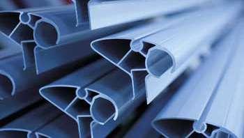
Extruded aluminium profiles are used to cover any exposed beams externally or internally. The assembly of the pieces use ‘clip‘ based mechanisms of attachment where they can simply slide on to pre installed rails installed in the prefab component. The curved extrusion finish is used to fit the aesthetics of the curved ETFE language, and the use of curvature in a extrusion basis of production doesn’t significantly increase overall cost. So this finish is used for the vast majority of finishing over the straight structures edges.
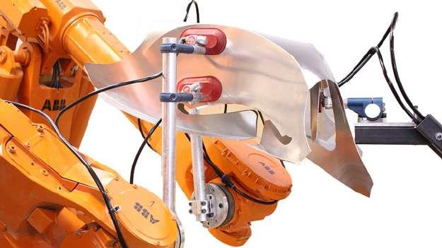
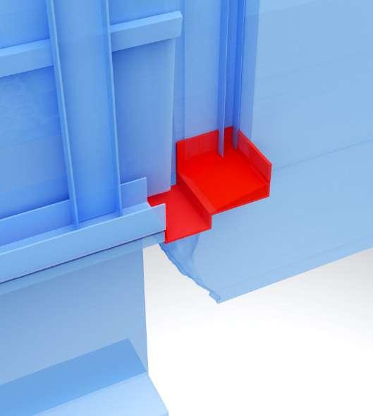
Double curved panelling is only used at the end nose (a) where an ETFE segment ends. Double curved panels are obviously minimised due to cost and are only needed instead of ETFE in this case due to the need to cover up the connection point to the floor plate. Due to the opacity of the ETFE and the desire to hide this detail, a solid element is used in the form of a double curved electroplated steel panels. Experimental use of multi axis robotic arms have allowed cheaper production of one off elements for double curved fragments. However the cost very much depends on the contractors used and the ease of repetition per fragment. But if the correct set up is properly organised this can be cheaper than conventional double curved panelling production.
In order for the structure to
which
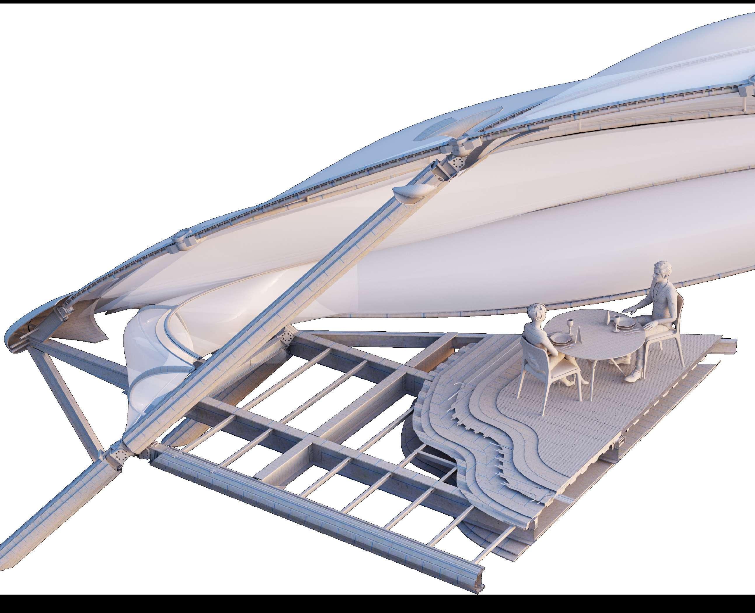
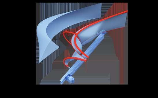
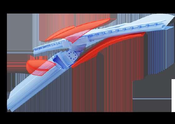
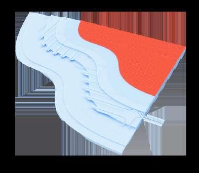
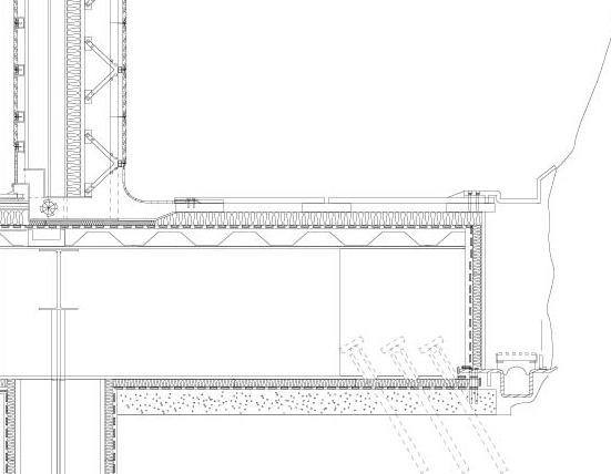
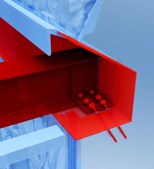
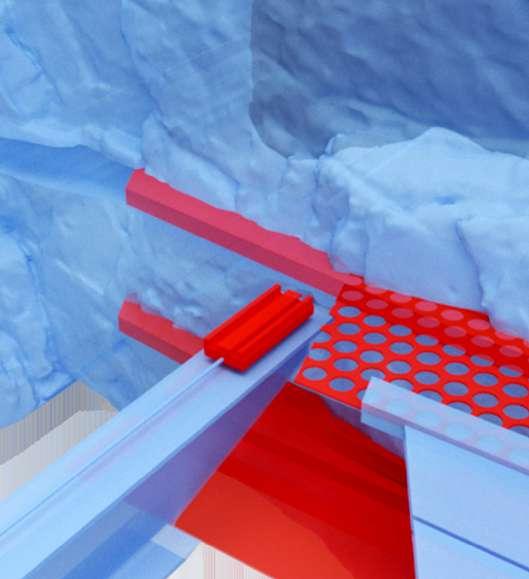
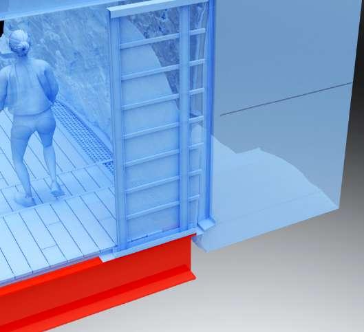
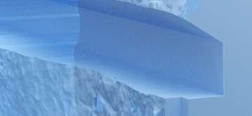
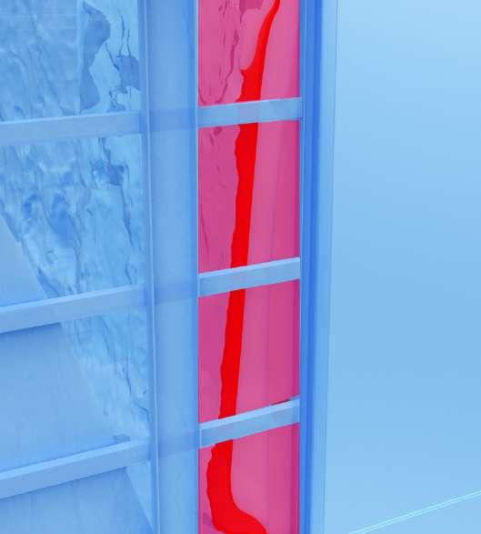
ETFE panels are used due to its qualities of weightlessness and translucency which are essential to the projects focus and experimentation of the project. The sequencing and installation of these panels consists of first installing a frame that connects and supports itself from the primary structure. Once completed workers proceed to install each panel by clipping the ETFE sheets in place and then inflating them through the pre installed air pipes.
ETFE LAYER
EXTRUDED ALUMINI-
UM RESTRAINT
RESTRAINT MOUNT-
ED TO UPSTAND
AIR PIPES
200 MM DIAMETER
STEEL TUBE
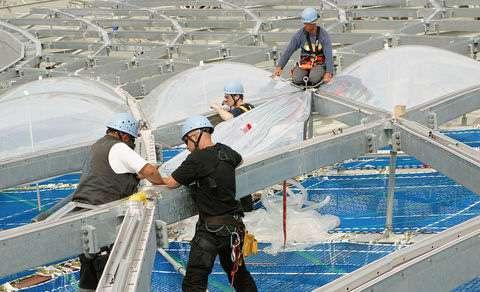
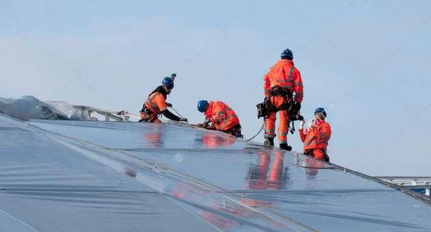
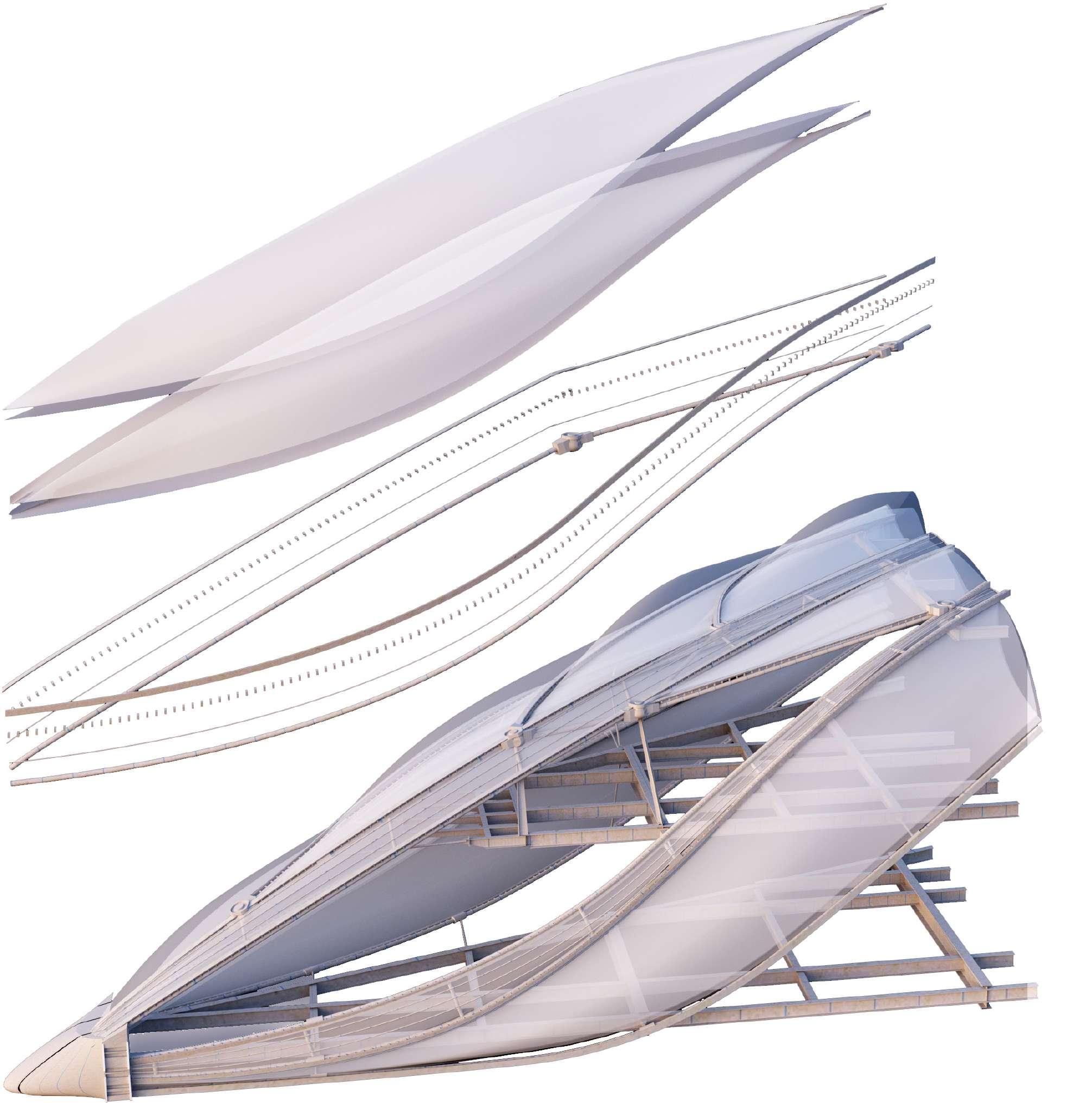
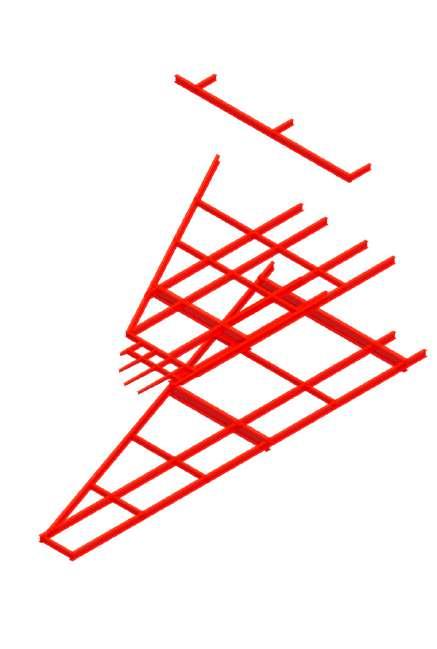
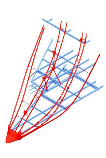
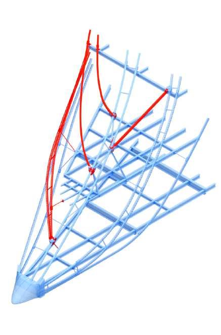
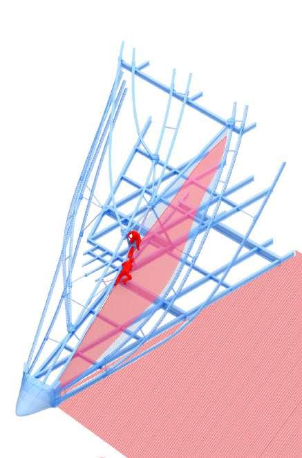
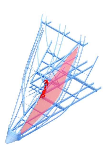
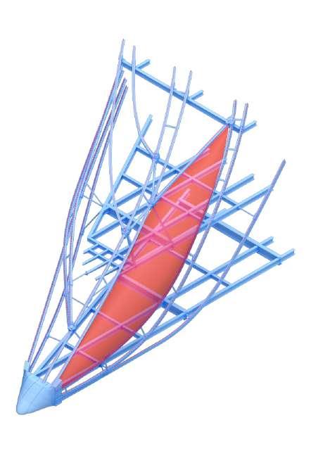
fig.25
2.10 FOCUS: CONNECTION BETWEEN SKIN STRUCTURE AND PRIMARY STRUCTURE
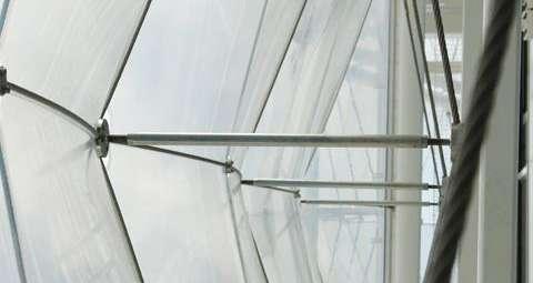
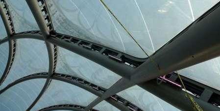
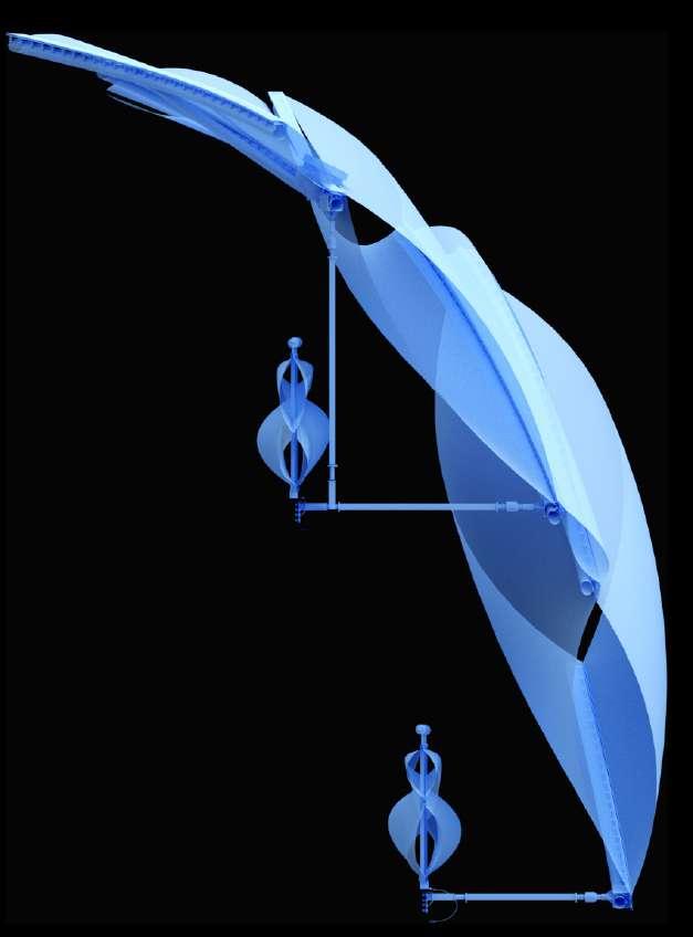
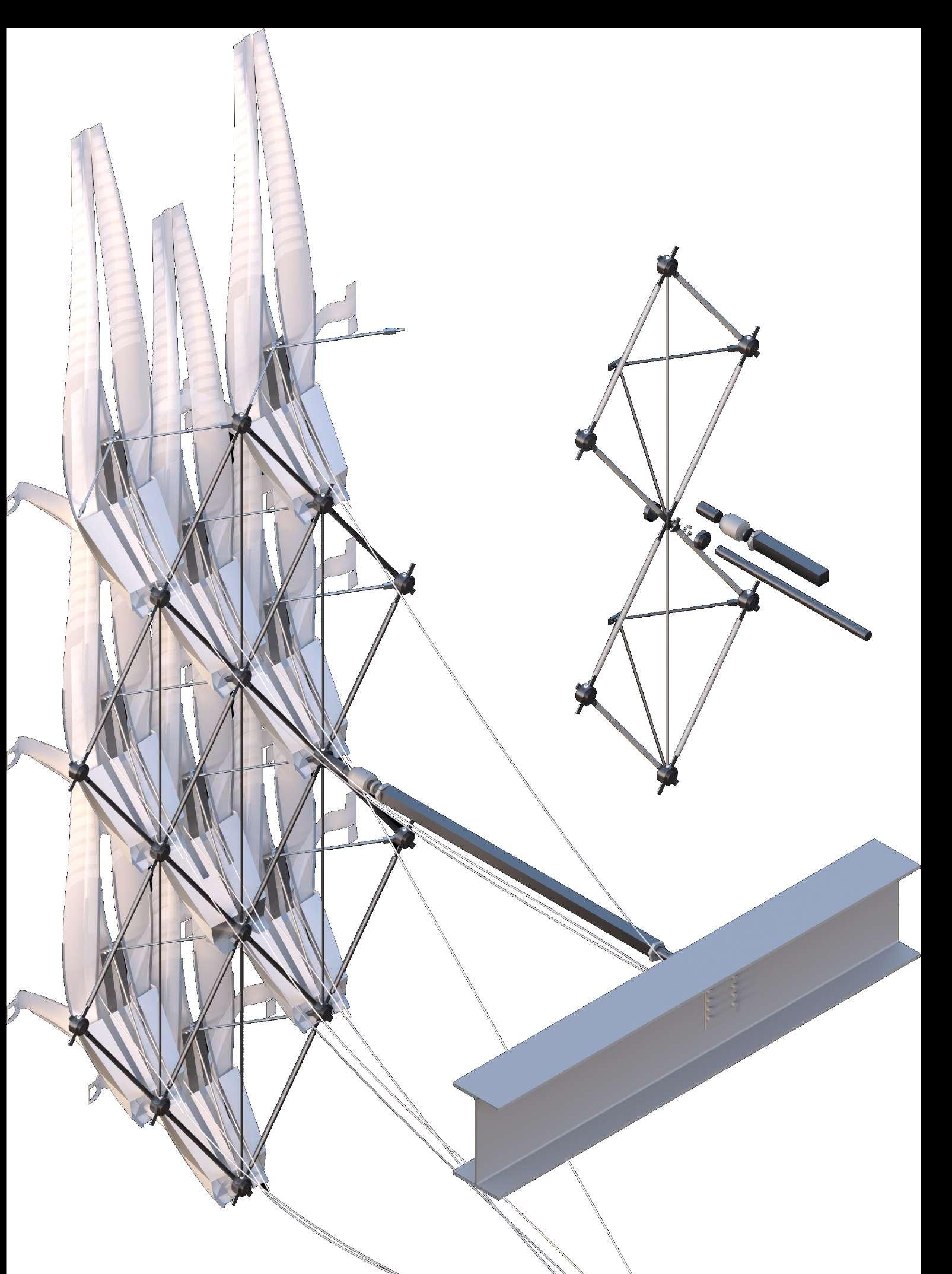
The secondary skin structure is upheld through fixing itself to the primary structure at key junctions as well as creating areas of self support by partially bracing itself by including self intersecting elements throughout the skins design.
SECONDARY STRUCTURE CONNECTIONS
In order for the frame to self support as much as possible, especially in long spans. The secondary structure upholding the ETFE was designed with intersecting elements that help brace the structure.
CONNECTION TO PRIMARY STRUCTURE
The secondary structure encompassing the ETFE envelop is supported by linking up with key primary steel beams so as to best support the frame. Varying support frames at different lengths can accommodate any varied angle of the structure. The distance left between the skin and the floor operates in a similar manner to the Alianz arena in Munich by HDM architects, where temporary walkways can be attached on the perimeter for any maintenance or pillow replacement required.
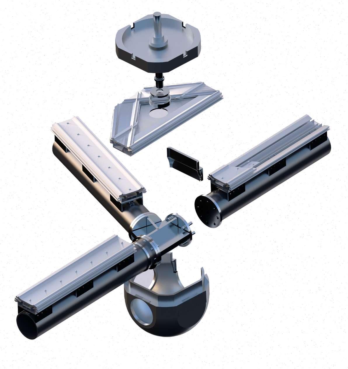
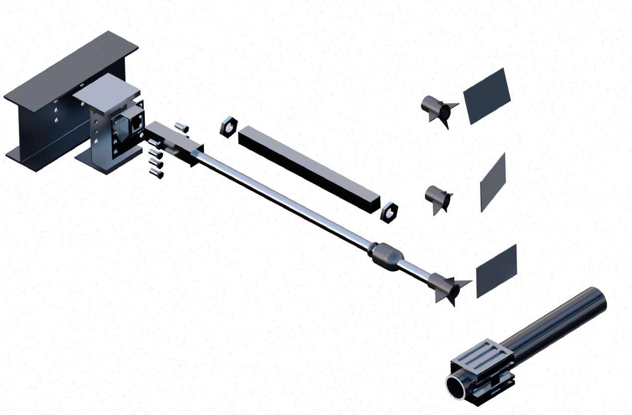
tube fitting (electroplated finish)
Steel plate welded to tube fitting (hot dip galvanised finish)
Adaptable angled steel,welded to plate for varied angles (hot dip galvanised finish)
Rectangular hollow steel (electroplated finish)
Aluminium covering
Curved steel tubes, with ETFE attachment
Frame attachment to primary structure
The secondary structure supporting the adaptive ETFE panels operates on a different system then the ETFE skin enclosing the rest of the building. A tight grid that accommodates each panel and laces the entire structure together is supported by the hanging structure The supporting skin is extremely lightweight due to the weightlessness of ETFE.
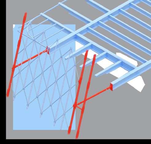
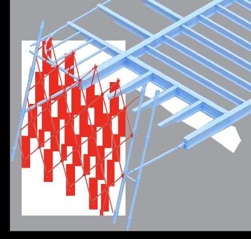
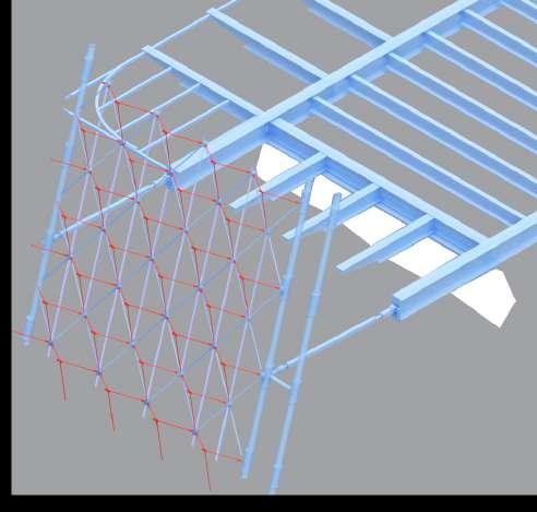
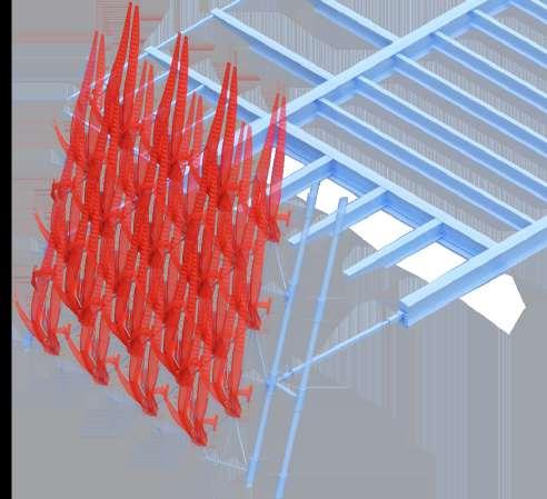
PRIMARY ELEMENTS
200 mm diameter tubes are placed on either side of the skins width and act as the primary structural elements, which are subsequently hung from the floor plates.
The grid placed between the primary elements both braces the skin as a whole through the diagrid structure but also accommodates each panels form which is placed within the framework. Variance of angles can be included.
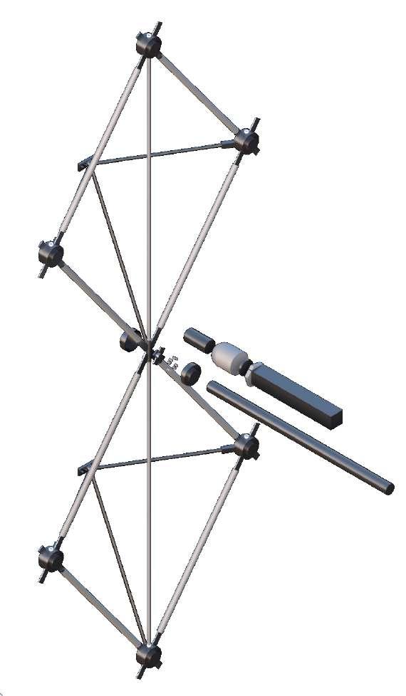
In order to accommodate the three dimensional design of the encompassing ETFE frame, smaller tubes are fitted within the structures joints to support each panel, each tube is only 15mm in diameter.
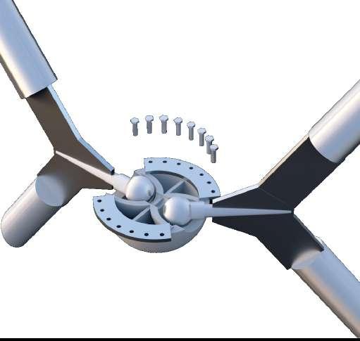
ROTATION
To accommodate the structure curving in plan, ball bearing joints are used to accommodate a span of angles up to 30 degrees. The vertical pipes connecting to the elements above help secure the joint and prevent uncontrolled movement horizontally.
Once the structure is placed each panel is fitted in with an easy assemble/ release fitting that will allow for an straightforward removal of the panel for any repairs or maintenance that is required.
In the initial design stage of the towers, straight vertical elements where to be designed whenever lining up with crucial floor slabs to suspend from. Curvature in elevation only happens in areas of transition or less critical suspension areas.
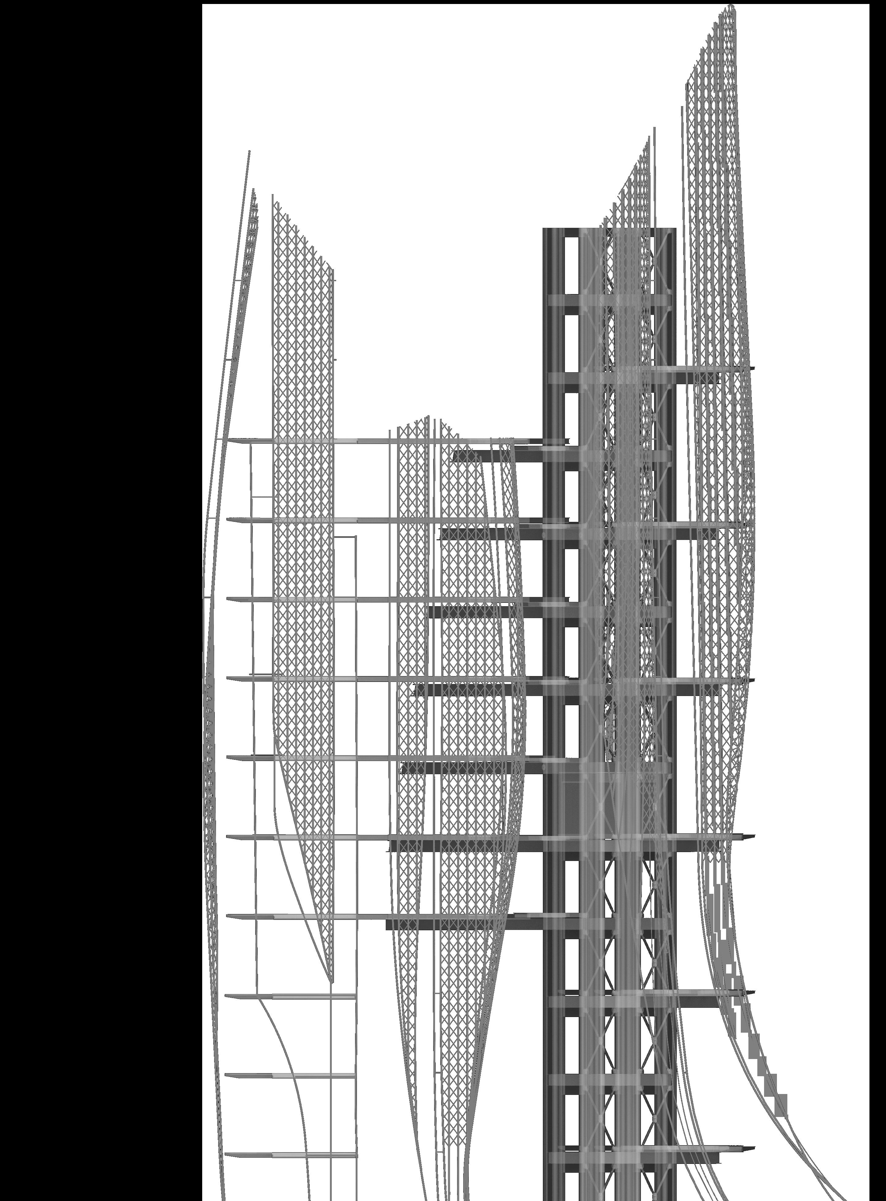
The tight grid allows for any subtle curvature to take place that would otherwise become stagnated with a more spaced out grid.
The diagrid pattern allows for both the fitting of the panels as well as bracing curved elements together in a tight weave.
Each skin element contains a double up of one of the primary supporting tubes to further brace the overall form.
Each 200 mm tube has been designed to join up with the surrounding frames so as to link up and transition to the ETFE supporting structure below.
are not
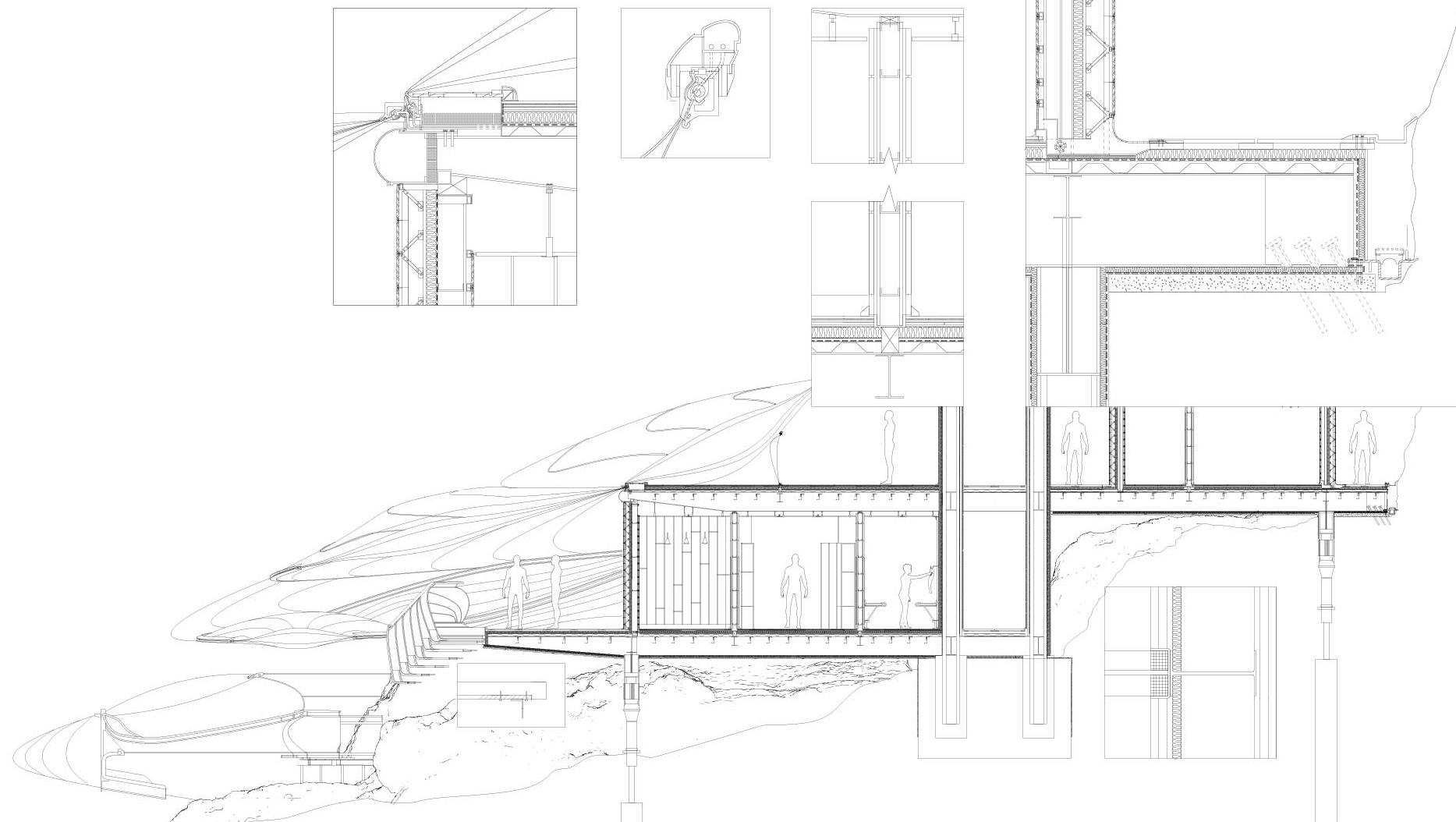
- External cladding must be ventilated in this type of build so a 50 mm air cavity is allowed for.
- The end noses of each floor contain ETFE clippings (11) to allow for each pillow to be inserted between floor plates where there is a link up. Air pipes run the edge of the floor to control the air pressure of each pillow, two pipes are used to allow for inflation and deflation of the pillows. Above the pipes is a grill (21) that can be removed if any repairs are required of general maintenance of the pillow. The rigid insulation can removed for maintenance.
- Shower rooms and other WC are mechanically ventilated and require a mechanical extract by statue therefore requires an air replacement grill from which the extract can go up and out of the building using the WC core
the ETFE skin must be light via artificial means. Rooms such as the kitchen and certain staff rooms require substantial lighting with no access to natural light. Developed and integrated lighting strategies are implemented within the rooms layout and interior design.
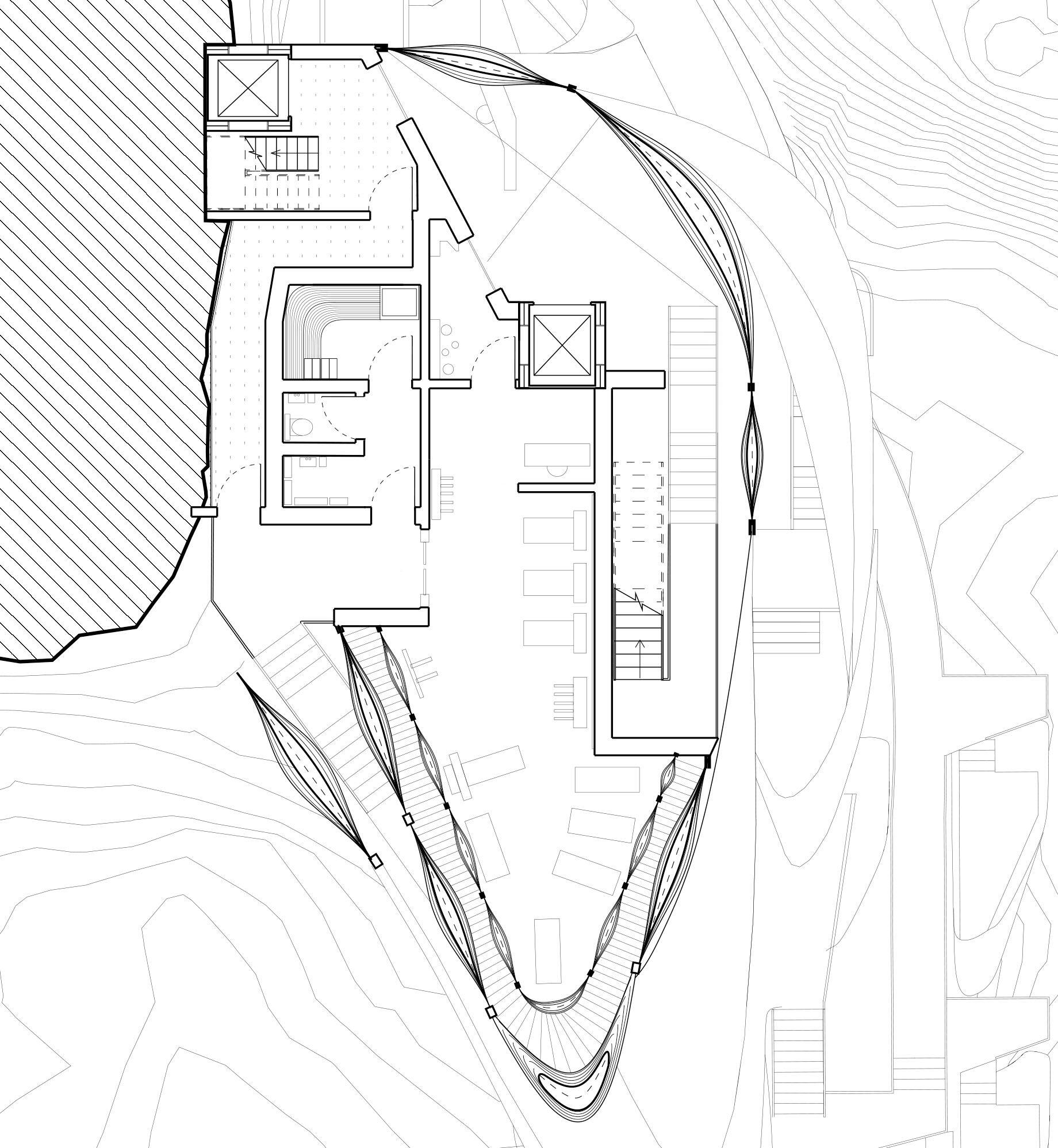
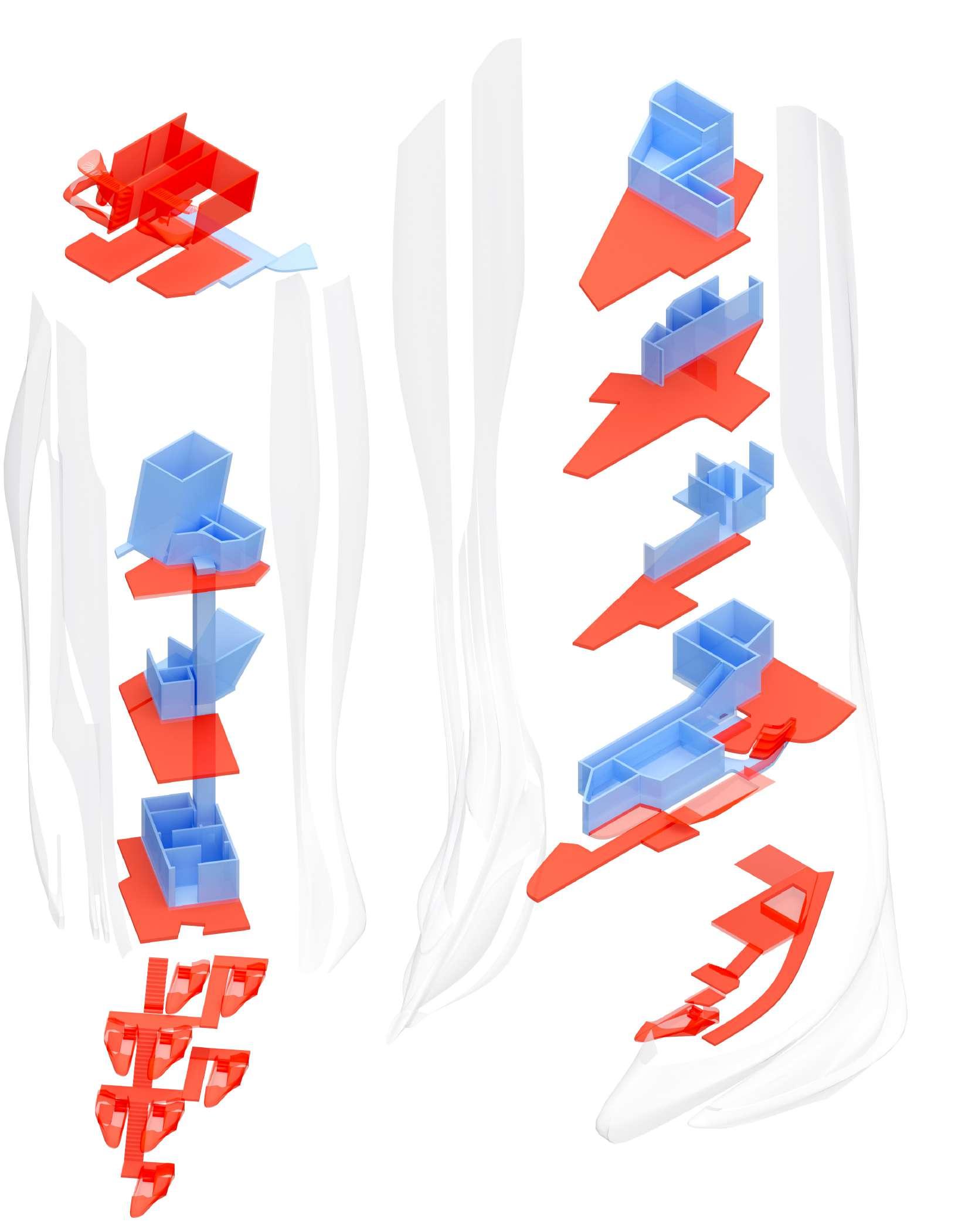
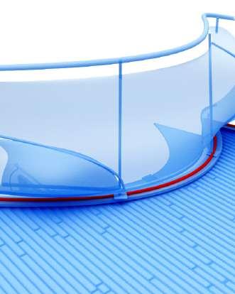
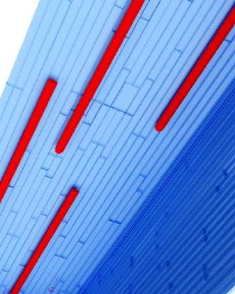
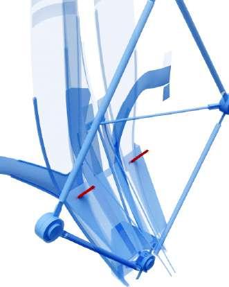
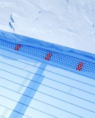
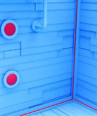
Each panel is fitted with small LED lights that are connected to the
In areas such as the external circulation along the mountain side where there is no natural daylight, lights are fitted into the floors construct.
Lighting in the pool is installed along the edges to provide subtle glow for evening use and further illuminate through the ETFE
use of the ETFE plays an important role in the night lighting strategy. Similarly to the Allianz
At
and
the
panels
is
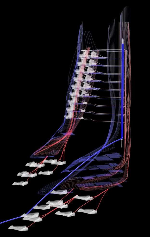
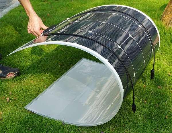
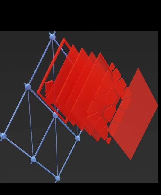
The buildings mechanical and electrical wiring strategy focuses on incorporating aspects such as mechanical air flow for the ETFE inflation within the design of the skin, alongside the use of the waters distribution system. Solar energy harvesting is gathered via solar panels which are incorporated into the formal design. These are mainly placed in the East tower which does not require daylight due to it being a maintenance and electrical room for the panels inflation sensors, water filtration and air source heat pump. Mechanised light systems are controlled from the maintenance facility located in the east core. Electrical wiring is placed along the edge of each room due to the embedded lights placed within the floors edge (part of the ETFE glow proposal). Certain areas such as the kitchen, laundry rooms and elevators require a higher voltage and are represented in red. Back up generators are also placed in the East tower besides exterior temperature sensors placed alongside the panels to moderate altering temperatures, sensors will activate whether panels on the tower are to inflate or deflate to allow hot air to escape as well as control light intake in the lower down areas of the building though either inflating or deflating the patterned ETFE panels to control light intake. Solar panels are used as a source of energy harvesting to be distributed around the building. All panels are south/ west facing to maximise solar irradiance, the flexible photovoltaic use an ETFE
or placed alongside ETFE panels The panels can be further adjusted in colour and opacity to merge with the aesthetic of the ETFE skin.
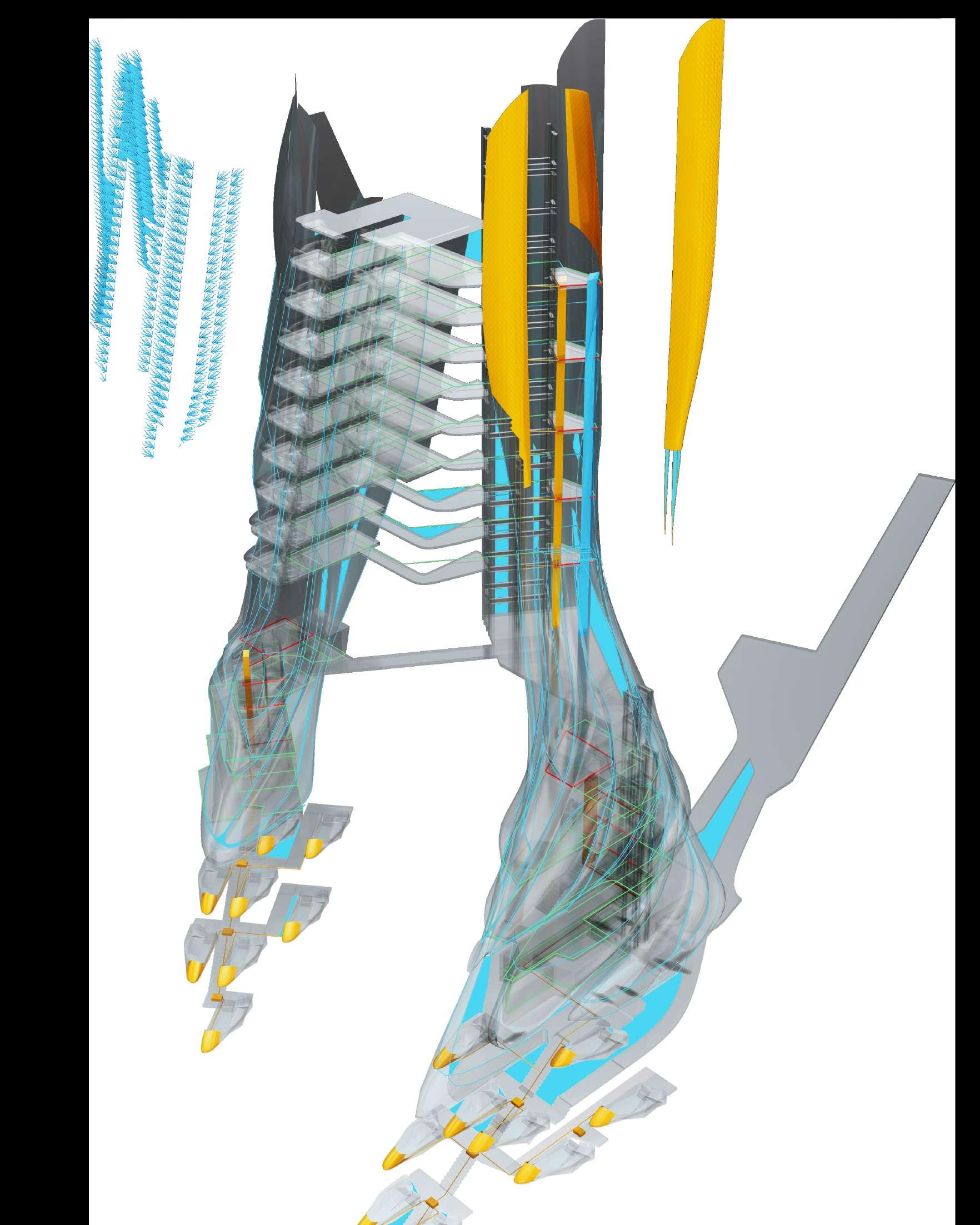
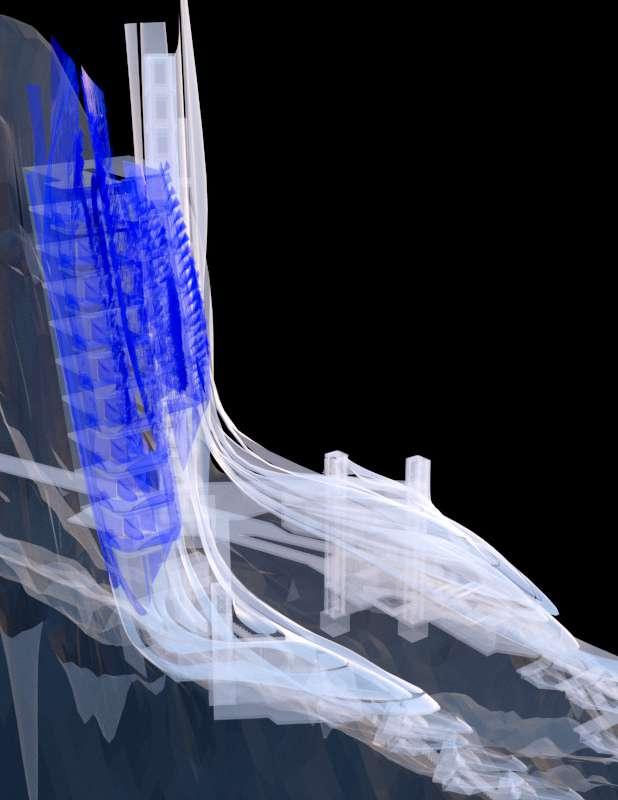
Blue pipes shows the wiring of air tubes located around the building. These are usually passed along the supporting skin structure and are linked back to the East maintenance core where thermal sensors dictate what areas require thermal intervention through inflation. Pumps for the tower skin are located in plant rooms in the east maintenance tower. Pumps are also placed in certain storage rooms to pump air into the ETFE skin in the programmatic areas below. Backup up pumps are in place in case of a failure. Air is sourced from the corridor cavities from the ventilation strategy, as hot air sourced from the exterior is less reliable when using pneumatics.
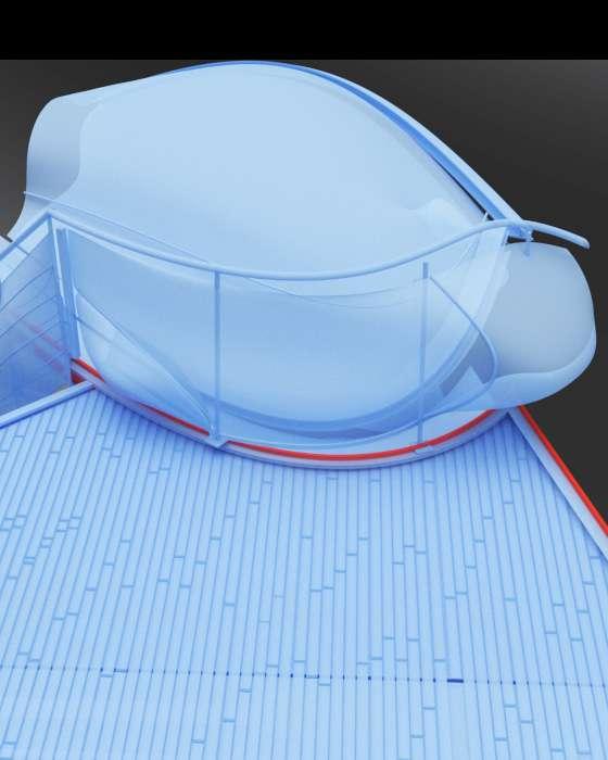
There is always two air pipes leading into each ETFE pillow to allow for inflation and deflation.
Solar panels are fitted into the same secondary structure used for the panels in the west tower. The flexible solar panels used can adapted to the curving surface and can even be included onto any ETFE surfaces by being glued on. However these surfaces cannot then be subject to any alteration in inflation due to the panels rigidity. The Solar panels do not allow any light through unlike the ETFE panels and therefore are only placed in areas that daylight is not essential such as the maintenance core in the East tower. The aesthetic of the panel can be altered from the standard distribution to follow a similar language used throughout the rest of the skin with the ETFE panels.
to the ETFE lighting system where lights are placed
or below the ETFE, artificial light is
be
Certain rooms in the building such as the kitchen, laundry rooms and other machine based rooms will require a higher voltage to be delivered to these areas. Elevators will also require a higher degree of voltage delivered then other areas in the building.
Electrical wiring runs around each room to feed into the floor integrated lighting system which lights the ETFE to create a glow at night. Wiring is also connected to sockets, switches for lighting, wifi etc..
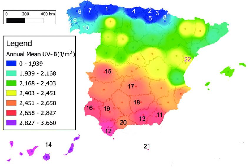
The nose of each pool, which contains the highest degree of horizontality is fitted with flexible solar panels glued onto the ETFE as these pillows do not vary its inflation. These areas were determined to be the most optimal areas of placement through the solar radiation analysis. Wiring for the electrical cables are placed under the staircases which are fitted with batteries on each floor. The wiring feeds back to the East tower core which contains the maintenance and sensor equipment.
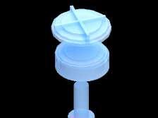
The water circulation strategy focuses on reusing and filtering grey water to be recycled and used in the pools as well as alongside the air source heat pump pipe system, which uses water to heat and cool space as needed. The East tower which is the maintenance facility contains a filtration water tank where water is pumped up to the top floor and filtered along its trajectory.
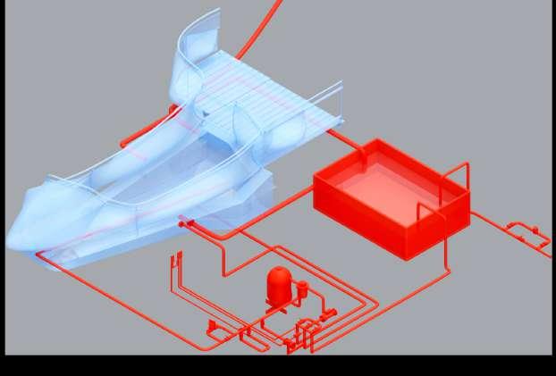
Heated pool water is sourced from the air source heat pump system. However to control the temperature of the pool on an immediate basis, each pool contains the same proportion of cool water stored beneath the circulation deck. The pool water can then be drained into this tank and swapped in for fresh water.
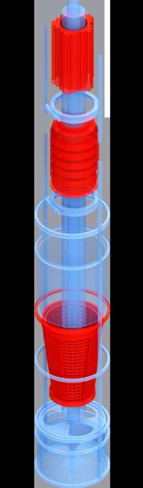
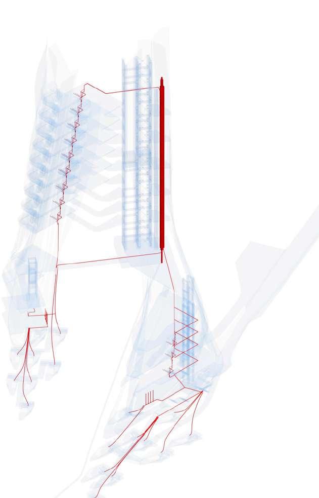
Grey water circulating throughout the building forms an enclosed loop where used grey water can be passed through the filter pump and reused in the pools below.
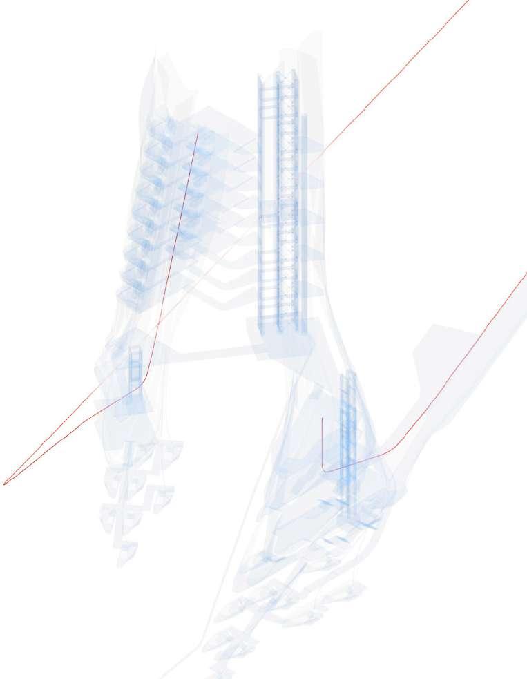
Toilets are lined up to minimise the black water piping to two main pipes. These pipes do not join up on site but travel either side to avoid black water crossing across the pools and producing smell. Sceptic tanks located on the perimeter edge of the building.
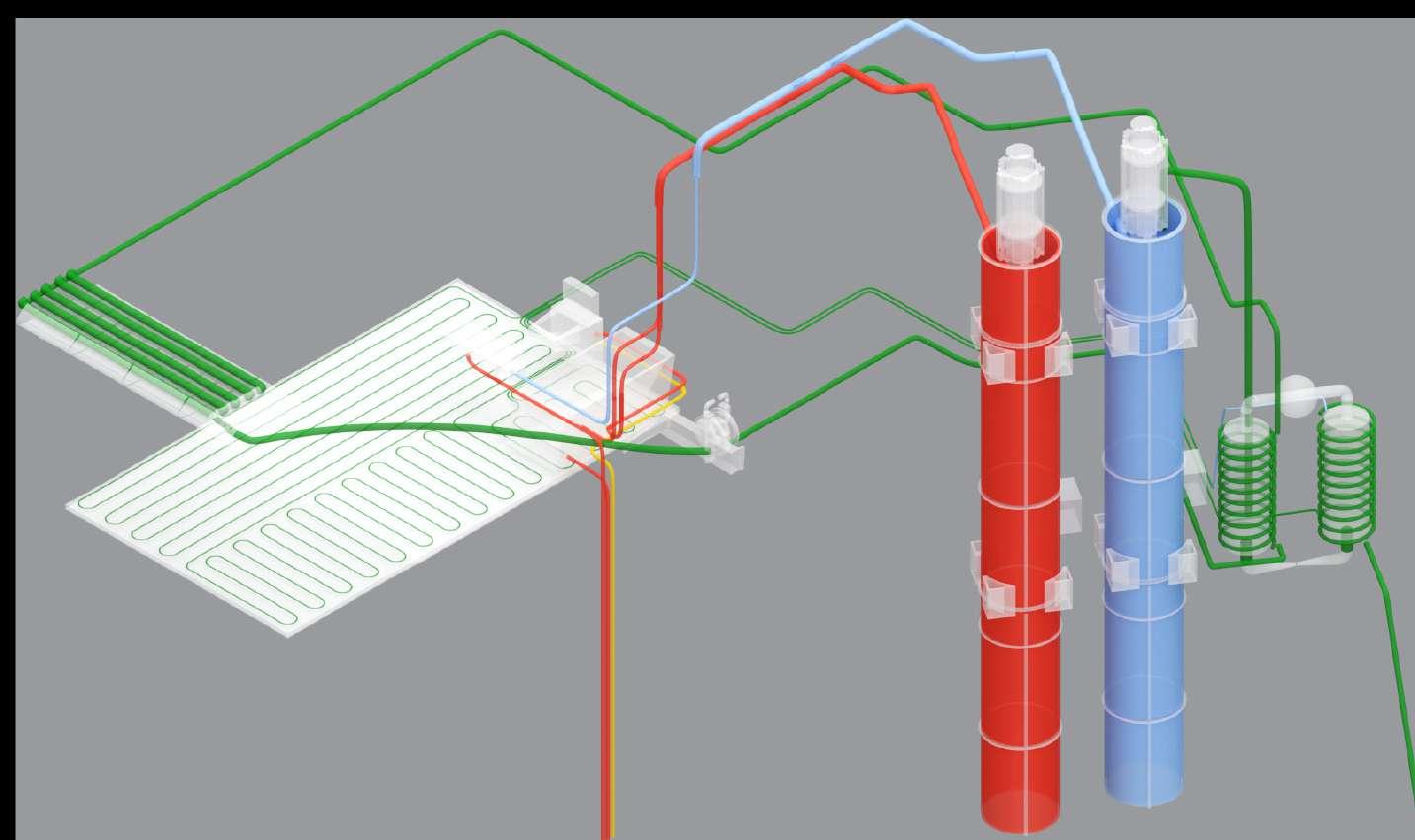
Drinking water
Recycled filtered Grey water
Air source heat pump water
DRINKING WATER TANK
Water is passed up the water tank and then distributed throughout the rest of the building for clean water sources
Water is originally sourced from the Embalse de tahodio reservoir less than 1.2 km away. This reservoir acts as the main source of water distribution to the city of Santa Cruz located a further 3km south of the reservoir. The reservoir has a capacity of 900,000 cubic meters of water. The water is then passed through the central tower core which has two water towers attached to it. One tower deals with clean drinking water, directly sourced from the reservoir. The other deals with recycled, re filtered grey water re circulating through the same tower. As the water is pumped up, it passes through a filtration system cleaning the water as it goes up. Due to the height of the tower, the pumping system does not pump the entire weight of the water in the water tower, as this weight would be too much for any pump to handle. Instead every floor it separates into individual compartments. Once the compartment is reached, water is passed along that floor. By spiting the water on each level, individual pumps can then pump water to the next level instead of pumping the entire weight held within the water tower
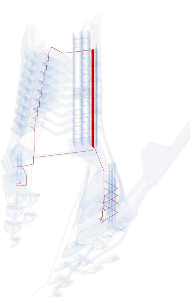
Black water
TEMPERATURE CONTROL OF THE POOLS WATER PUMP FILTRATION SYSTEM
The pools rely on the heated water from the air source heat pump for hot water. This Is especially needed during the winter which is why the vertical strategy of the heat harvesting suits the low winter sun. Page 3.01
However even during summer months hot water is sill needed as the users have control over the desired temperature of the individual pool, and can be heat the pools temperature significantly higher than an exterior pool that would only be heated by sunlight.
At night the pools are drained of the water which will be dirty from constant use and is replaced with fresh water located in a basin under the walkway. This basin also allows for cooling the pool if the water delivered from the air source heat pump and the external temperature proves to be too hot.
WATER
Heated water is feeds into the pool from the air source heat pump system, the tubes travel to the pool along the skin The tank contains cool fresh water to be
at
or during the day to cool the pool. Separate tank is used for recycled water from the pools that feed into the grey water recycling system Separate tank is used for recycled water from the pools that feed into the grey water recycling Recycled grey water feeds into what would eventually become black water
Sceptic tank
Sceptic tank
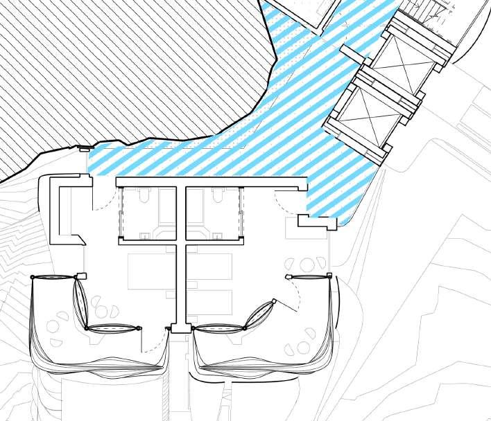
The ventilation strategy uses cold air trapped between external walls and the mountain to ventilate the building and prevent overheating the building. The spaces in which the air is trapped are ‘external‘ corridors with no thermal enclosure and are designed as such to prevent the build up of moisture and humidity from entering the buildings weatherproof line. Therefore these spaces/ cavities are used as circulatory spaces that don’t require an enclosed insulated skin around it. Air is passed through a fan beneath the external wall to allow the breeze to pass into the neighbouring room. When the window is opened at the far end, air can pass straight through the room and past the balcony, cross ventilating the room.
MECHANICAL VENTILATION
All WC and showrooms require mechanical ventilation, separate from the natural ventilation strategy.
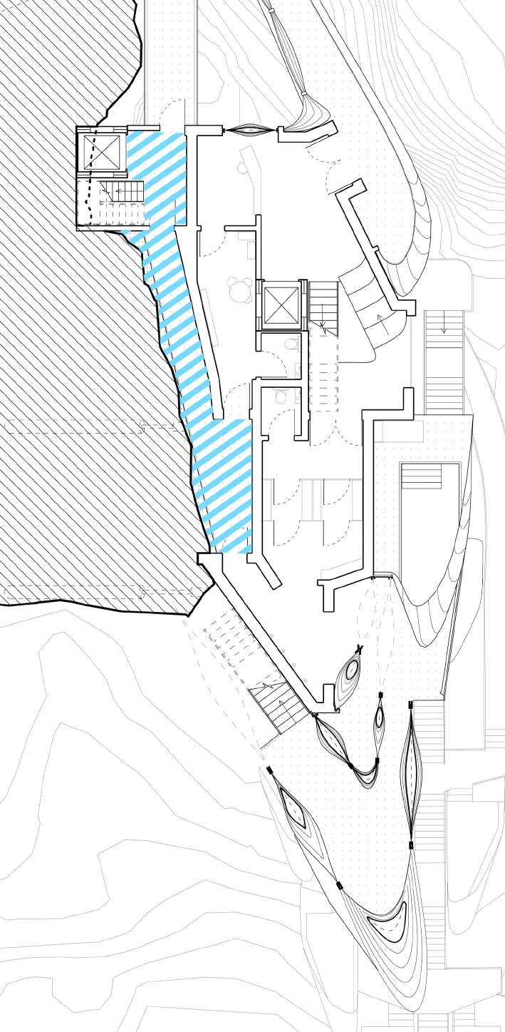
ROOM VENTILATION
Cool air passes underneath the wall via the air duct, passing through a fan and into the next room.
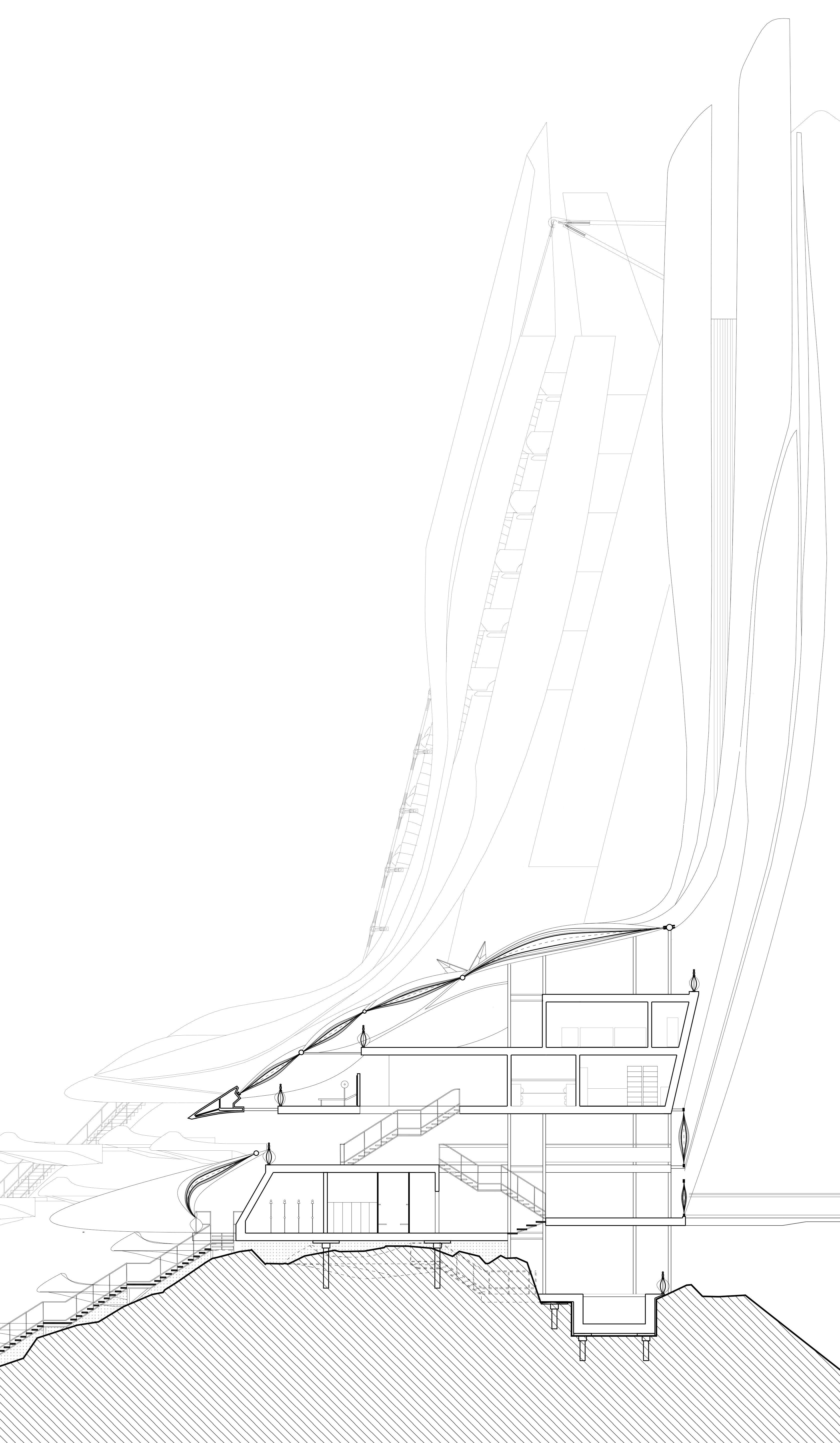
To allow air to circulate around the building through stack effect. The 1 meter gaps left at the end of each floor allow for air to travel up each floor and exit via adaptable panels that can be opened to allow air to escape. Similarly used in the Eden project.
CROSS ROOM VENTILATION STACK EFFECT
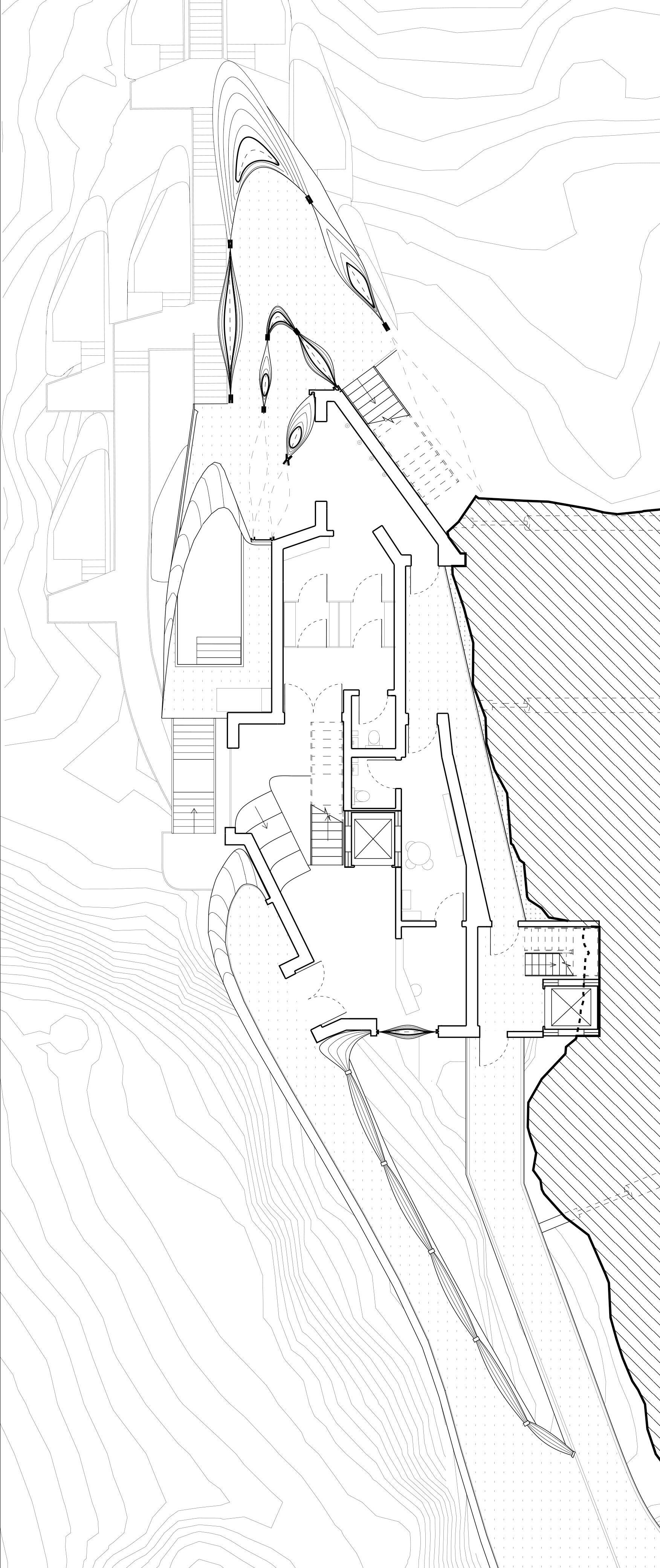
Areas such as the lobby space will contain ETFE windows that can be opened to allow cross room ventilation along the central space, the main lobby doors can also be left open. On the ground floor especially where the changing room walls do not need to reach the roof and the shower room and locker room are partially open. These opened spaces allow for cross room ventilation.
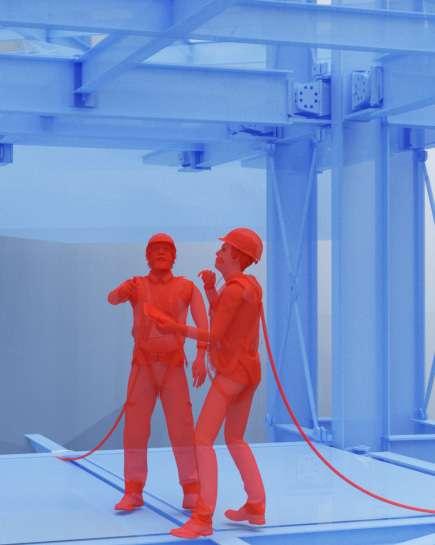
Key health and safety risks to be addressed in this project are factors of working at significant height. Safety of the workers during construction at height must be considered, and how work is carried out in these conditions. The use of safety harnesses will affect the work flow of a construction worker and will require professionally trained workers experienced in working at height. Workers will also have to be trained in working in conjunction with the air crane in time sensitive unloading of deliveries.
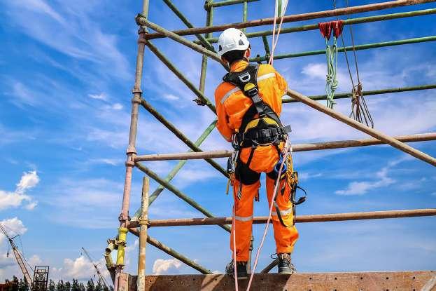
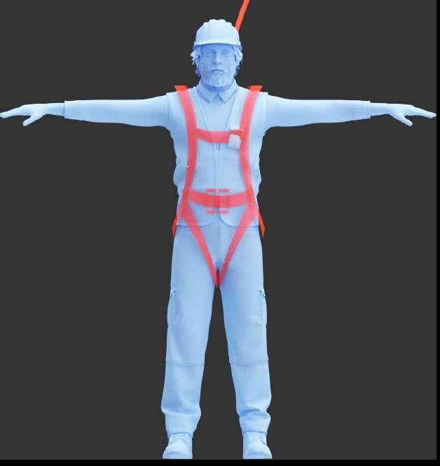
are worn when working at height and where safety
has not been installed.
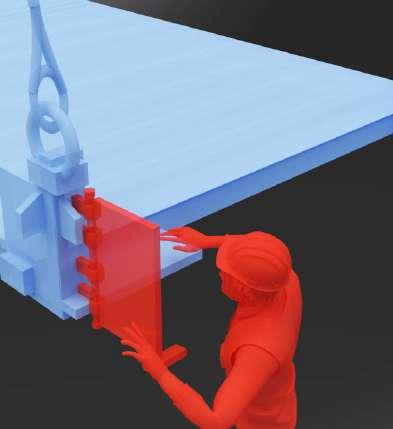
AIR CRANE DELIVERIES
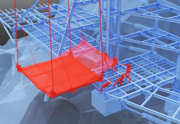
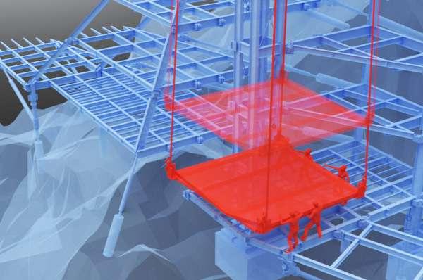
The minimum height required between the air crane and the cliff was a deciding factor in the sequencing and angled form of the design. The slanted angle of the cliff and subsequent tower allows for each component to be delivered and handled whereas 90 degree angle would not allow the air crane to approach as closely. This delivery approach means the load can be delivered vertically downwards and avoid swinging which could hit workers.
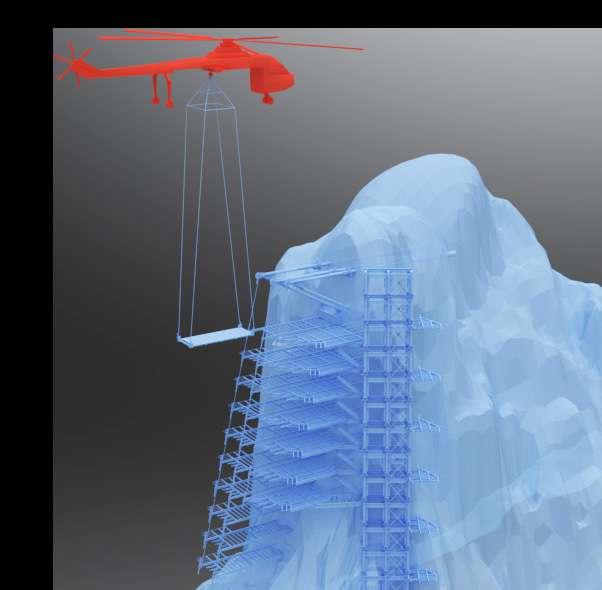
A key factor that had to be taken into account during the design is the distance and angle that the air crane can approach the building. When deliveries are closer to the cliff the air crane must move higher up due to the radius of the blades
WORKING AT HEIGHT
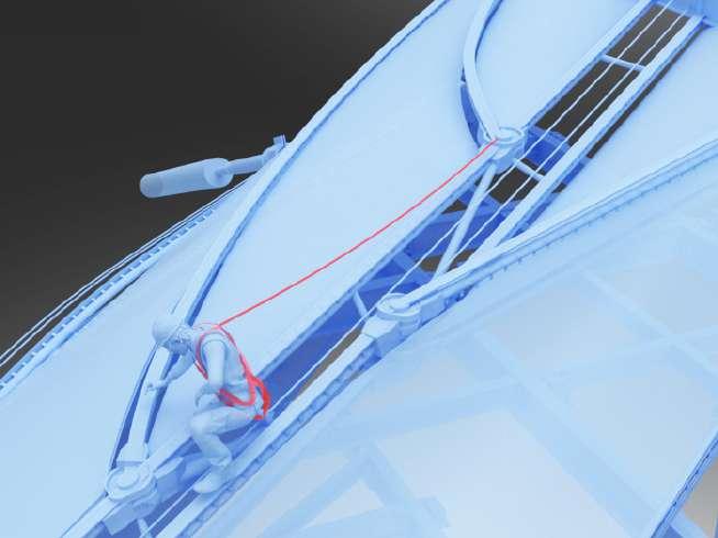
Most of the work is done at a significant height where a fall would be fatal, which is why workers are required to wear safety harnesses when working in theses areas. However the use of harnesses slows down construction due to the need to constantly re hook the safety cord every few metres. Therefore certain areas contain scaffolding balustrades and temporary floors are also placed so that workers can move around the site without the harness when it is safe.
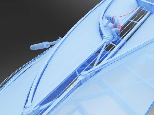
The distance of the cord is based off of how far the fall would be until you hit the first item below. Therefore the length of the cord should be between two to three metres maximum.
DEBRIS AND GUARD RAILS WEATHER
A key safety concern when working at height, is the falling of objects down below. Whether these are tools, materials or rock debris, the workers and building below must be protected from any potential risk of falling object. Therefore safety nets must be placed in key positions to catch any debris. Different nets are used in the excavation process where rock is expected to fall at a continuous rate, whereas the nets used as a standard precaution will not be stressed as much to deal with such a high capacity of load.
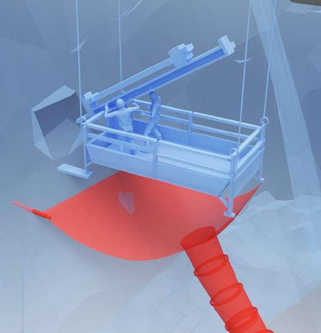
Before drilling takes place, netting must be installed to catch any rock excavated. Attached to this is a debris chute that will then safely direct the debris down below.
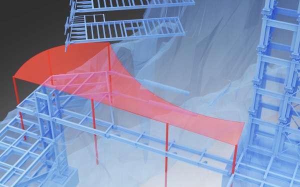
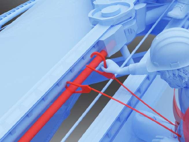
Factors of weather such as wind, rain and heat can affect the safety of workers especially when working at extreme heights. Fortunately Tenerife has a year round warm climate, so dose not experience particularly extreme levels of heat or cold, and the site is protected from strong northern winds due to the mountains dispersing the majority of wind flow in comparison to the other islands.
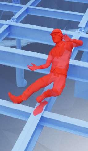
During the summer the days average at 250C, which is not deemed a dangerous working temperature, however due to the sequencing of construction, workers will be exposed to sunlight for the majority of the construction phasing as the buildings skin finishing will only happen in the later stage of construction. Therefore the nets used will also be used as a form of shading so that workers can either work in the shaded areas or take their brakes in the shade. If there are days of extreme heat, where heat exhaustion could be an issue, work can be rescheduled to avoid the times of day of high peak temperatures.
Safety nets are placed in key areas of the building to protect the workers and the building from any risk of falling equipment during construction. Nets are attached to existing structure where possible, otherwise temporary scaffolding is erected to assist.
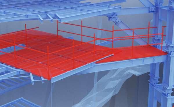
Safety harnesses
scaffolding
4.03 FOCUS : ADDITIONAL MEANS OF QUALITY CONTROL
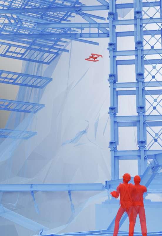
Due to the remote nature of the site, additional quality control measures must be implemented to ensure the delivery of both a safe and high quality build. The cliff being a topographically challenging site to build on, the 3D scan of the cliff must be extremely accurate due to the prefab elements being bespoke manufactured to fit the form of the cliff. To ensure this, especially at height, drones will be used in both site analysis and in certain difficult to access areas for quality control during the build to provide up close visual imagery and data. This will ensure that the high end prefab elements are designed to a high tolerance based on up close data provided by the remote access capabilities of the drones, otherwise limited by human accessibility.
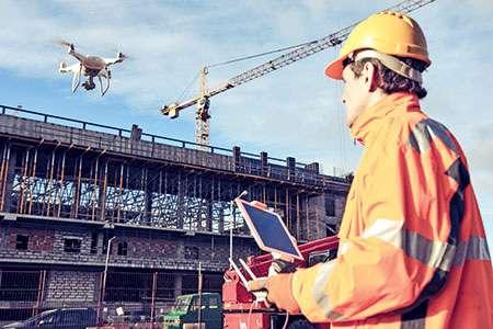
DRONES IN QUALITY CONTROL FOR REMOTE ACCESS
The use of drones in construction is becoming more popular due to the range of capabilities of having an aerial perspective, especially with a high rise construction where access to areas of height is both time consuming and potentially more dangerous from more frequent visits.
IMPROVING VISIBILITY
A project such as this, requiring accurate and time efficient operations during prefab deliveries, efficiency and safety become very high priorities. Drone operators allow managers and contractors to view the entire site, especially in certain areas where they do not have the training to access an area of the build. Being able to get up close to otherwise hard to access areas help control potential flaws that might occur during construction from a lack of visits or observation.
MONITORING LARGE SITES
Monitoring a large site can be problematic, if an issue goes undetected and unreported, setbacks delays can occur, affecting the time frame of delivery.
A multitude of drones can provide comprehensive aerial surveillance from a every angle, allowing project managers to quickly respond to any accidents or issues.
KEEPING PROJECTS IN SCOPE AND ON BUDGET
Drones are an overall an cost-effective investments as they can perform and host various tasks such as mapping, aerial surveillance, and surveying hazardous and unreachable areas.
Drones can also be used to track the weather to provide fast and accurate weather reports which is essential when dealing with weather sensitive machinery such as the use of the air crane which cannot operate beyond a certain mph of wind. Drones could also be used in assisting with inventory control, relaying accurate stock reports to contractors and clients.
IMPROVING SAFETY
Through the ability of monitoring a wide area from a single location, it should allow for project managers to detect any kind of safety risk and quickly take action.
AERIAL PHOTOGRAPHY
To keep the client updated on the progress, and potential difficulties of visiting the site during construction. High res 360 aerial photography will allow construction shots of the site to be easily relayed without having to visit.
ANALYSIS AND EXCAVATION AT HEIGHT
The use of drones can play a key role in at height work during both site analysis and during construction. The ability of a drone to reach areas otherwise more difficult to access in person, speed and safety of the work is increased trough reducing the amount of visits in person in some of the more dangerous areas of construction The drones ability to get closer to the cliff will also enable a more accurate 3D scan of the cliff to be created, which is vital to the assembly and design of the buildings construction.
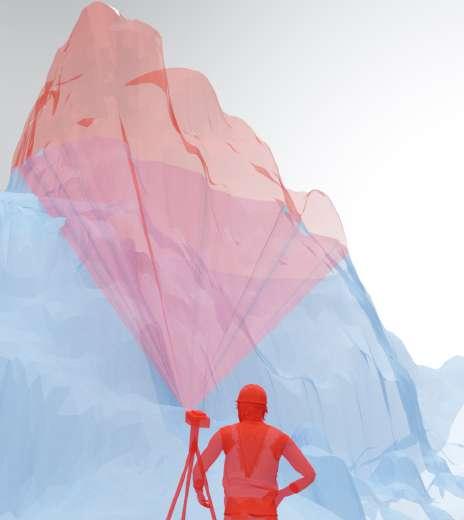
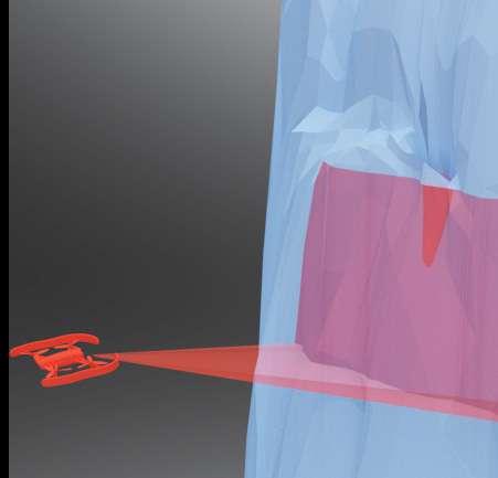
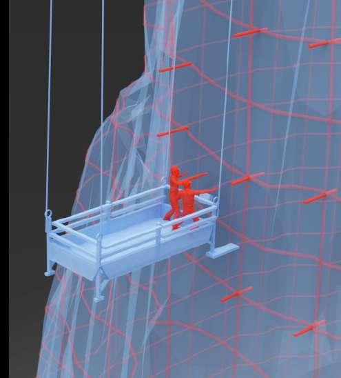
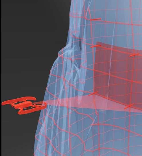
Prior to excavation of the cliff, the site will be marked up with key location points to allow workers on site to know exactly where a specific depth must be drilled. To minimise the need to transport workers along the cliff again a drone will be used to then scan these physical mark ups one completed and the results are compared with the original design to ensure the placings are accurate. A difficult task at height and with varied topography such as the cliff.
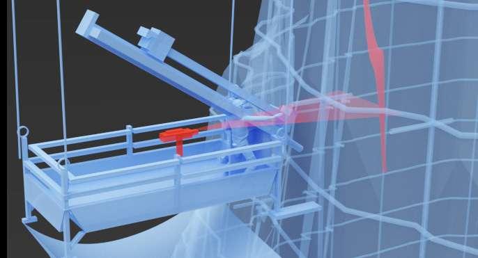
ACCESS AND MEANS OF QUALITY CONTROL OFF SITE QUALITY CONTROL
To facilitate the operations of contractors and in general any workers that are not trained at height, to visualise some of the higher, more difficult areas of access on the construction site, drones will provide the visual imagery required. Systems are also in place to ensure fast communication with workers and allow contractors on site to be able work effectively and visualise complicated and precise instructions through the use of AR technology.
Construction projects such a this, which require an extremely high level of accuracy, and mistakes of tolerance or details would cause significant additional cost. AR can allow for workers to practise difficult manoeuvres before hand, especially time sensitive situations such as the deliveries as a complementary additional training to the actual physical training. The technology also allows for details to be highlighted in real time on site due to augmented reality elements, essential when travel between the office and back is difficult. Contractors can therefore receive additional data to navigate the projects progress, avoiding costly mistakes in the process. AR has the ability to render each component of the construction project, and provide detailed instructions on the spot for workers to look at. This would help with the time constraint of certain situations. An AR program can also build upon the real world, allowing workers to visualise existing elements such as plumbing and wiring that is not as visible due to the prefabricated elements.
The use of a prefab construction system is both needed due to the sites restrictive terrain but also to ensure the delivery of a high end build that is required of this type of resort. The use of a modular prefab system ensures the work produced and the quality control conducted on each element can be done to an extremely high level whilst the element is protected in the controlled workspace of the warehouse. Whereas a similar level of accuracy would not be possible on site.
To allow site managers to conduct regular maintenance, health, and safety checks in difficult to access areas, especially if the individual is not trained to work at height, drones will be used to provide visual imagery of non accessible areas to these groups of workers or contractors, providing imagery for construction inspections, engineering inspections and industrial inspections . Additionally, due to their size and manoeuvrability, drones can fit into tight places where workers might find it more difficult this could be especially useful for tight spaces in between the rock and the building. Equipped with a range of video cameras and thermal sensors, drones be equipped to provide more than just static visual imagery.
MATERIAL MANAGEMENT AND INSTALLATION
Materials are delivered and inspected at the assembly facility prior to being stored in the warehouse to detect any defects early on in the process. Assembly of a majority of components can then take place without the interference of wind, snow, rain or extreme temperatures minimizing impacts on schedule or quality.
HIGH QUALITY
Modular construction companies usually have strict quality programs with best practice requirements that ensure a high quality of construction. A modular assembly line allows for an controlled plant environment with excellent quality control programs in place, which cannot always be maintained to a similar degree with traditional on-site construction.
EFFICIENT COORDINATION OF WORK
An efficiently designed manufacturing facility allows for an efficient sequencing of work and fewer conflicts in scheduling. This therefore contributes to less rework or error during assembly, as well as producing less debris or stored materials, significantly less construction traffic and more performative installation processes.
DILIGENT SUPERVISION OF WORK
Each level of the modular sequence contains regular quality checks. With checklists used to monitor the quality of the work. Supervisors supervise modular components during every stage of construction, to make sure that each component meets the required criteria, therefore reducing errors..
THIRD PARTY AND CONSULTANT REVIEWS
To ensure the necessary contractors and workers can access the site early on in the construction, one of the first elements built onto the structure will be the pathway to the site. Allowing for any manual quality checks to take place from the begining. SITE ACCESS
Modular Construction buildings will often undergo third party reviews to ensure the degree of quality is maintained. Clients, consultants can easily and safely visit the manufacturing warehouse in order to verify quality and view assembled components before delivery to site.
IMPROVED COMMUNICATIONS
In standardised construction, project teams are usually constituted of various subcontractors leading to confusion, and misunderstandings. Prefab construction systems improve communications at every level of a project to make sure that information is exchanged in an efficient manner. The ability to allow designers and trades to work together within the manufacturing facility creates an efficient system of communication.
EXPERIENCED TEAMS AND WORKER SKILLS
A fragmented system, with poor communication, will lead to poor quality work. In areas where one subcontractor’s range of work overlaps with another’s often a results in some deficiencies. Prefab construction allows multiple tradesmen at each facility to work together for long periods of time, leading to collaborative methodology that ensures the delivery of high quality product.
A combination of traditional scanning as well as high up and close scans from the drones will
3D SCANNING OF SITE
fig.34
4.04
FOCUS : CONSTRUCTION REQUIREMENTS IN TENERIFE PARK ZONE
The location of the site is situated in a rural park reserve. Construction is allowed in these areas but is limited and must conform to the Canary governments regulations that are in place to conserve these biodiverse parks. The proposed build must conform to certain ecological and cultural regulations such as being energy efficient and respectable of the local landscape in order to get planning permission. This page outlines 8 of the specified requirements listed in the document sourced from the Tenerife government and planning site. To briefly summarise the document, it mostly states that the proposal must be self sufficient and implement environmental functions within the design. Aspects such as the thermal strategy of the building and its use of sustainable energy production help conform to these regulations.

The guidelines are layed out by Canary government Ministry of ecological transition, fight against climate change and territorial planning. The information was sourced from https://www.urbanismosantacruz.es/ es/vigentes-en-tramite specifically document, TENERIFE-Modesto Campos-EstudioDetalle-Informe Final-rev.190 informed the guideline manifesto this project follows. Translated from spanish to english via google.
Due to the surge in tourism in the Canary islands, the government has placed previously non existent building regulation throughout the islands. To prevent ‘untasteful‘ construction in some of the more rural zones. Regulations have been implemented to determine the quality of build in these protected zones. Nearly half of the islands territory (48.6 percent), is under protection from the Red Canaria de Espacios Naturales Protegidos (Canary Islands Network for Protected Natural Areas). Of the 146 protected sites under control of network in the Canary Islands archipelago, a total of 43 are located in Tenerife, the most protected island in the group. The network has criteria which areas under its observation are placed in eight different categories of protection, all of them are represented in Tenerife. Due to the buildings location in a natural reserve the project must adhere to specific ecological preservation and contributive elements. The titles listed on the right are the required objectives that the Canary government Ministry of ecological transition state must be fulfilled in the proposal order to obtain building permission within the particular zone. The main requirement revolves around a successful integration within the site, with an emphasis on the preservation of local flora as well as a self sufficient building that can operate partially off grid and react to potential changes in global warming any adaptation of the immediate environment must also configure with existing social layouts and not imped any existing social infrastructure.
1- BUILDINGS INTEGRATION WITHIN THE SITE
• A regulatory zoning between homogeneous urban areas and buildable areas, where one must consider the fundamental characteristics of the urban landscape and values present in said urban landscape. To be interpreted but acknowledged in the proposal.
Architects response: Attempted integration of site through minimising drilling through tactile placement of elements in horizontal areas, as well as using structural strategies to minimise the use of drills.
•The location and conservation of tree plantation so as not to affect the visual perception of the environmental appeal of the site
Architects response: The majority of the building is solely placed into the rock, some vegetation remains lower down but is only affected when a pool is placed, The vast majority of the vegetation will remain untouched as the constitution will be limited on top of the existing structure. The use of prefab elements will reduce construction debris and site space usage that could harm the flora.
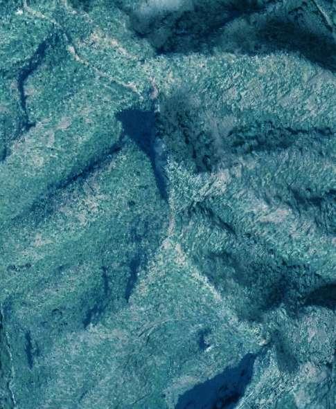
2- CONTRIBUTION TO THE CURRENT ENVIRONMENTAL SITUATION AND POTENTIAL EVOLUTION
•The proposed build must take into account the local environment the project is built in and attempt to use these conditions so as to correspond with any future adaptations of a self sustainable proposal
Architects response: The projects focus revolves around harvesting renewable energy through the use of a thermal/ solar based heating system for the pools. Solar panels are also integrated within the skins design for the use of renewable energy in the project.
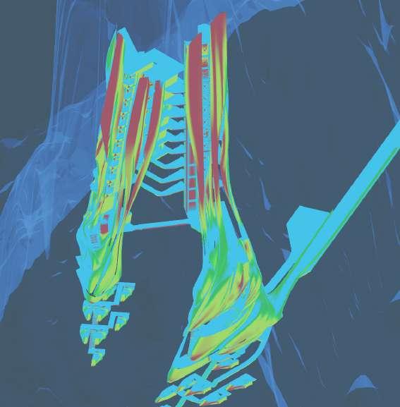
3- HIGHLIGHT ENVIRONMENTAL CHARACTERISTICS OF THE AREA THAT MAY BE AFFECTED IN A SIGNIFICANT WAY THROUGH THE PROPOSAL
• The environmental aspects of both cultural integration within the environment and landscape must be considered. As part of any building scheme within the area the company to build must pay for a detailed analyses of the area to help document the geological and environmental data of the area.
• Landscape: The descriptive analysis of the landscape must be conducted whilst taking into account the varied and most prominent components of the landscape and how these interact with the proposed building.
Architects response: This landscapes environment in particular is characterized by extremely prominent mountains and hosts multiple hiking routes that are active in this area due to the its vast biodiversity. The project aims to encompass the existing form and angle of the cliff in its design to minimise impact.
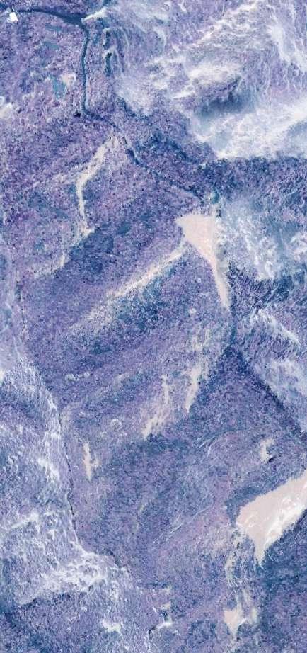
4- HIGHLIGHT ANY RELEVANT ENVIRONMENTAL PROBLEMS WITHIN THE PARTICULAR SITE, ESPECIALLY AREAS THAT ARE IN THE NATURAL RESERVE AND PROTECTED SPECIES FROM THE NATURAL PROTECTION ACT OF 2000
5- ENVIRONMENTAL PROTECTION OBJECTIVES IN RELATION TO INTERNATIONAL, NATIONAL AND COMMUNITY CRITERIA, AND HOW THESE CRITERIA MIGHT BE ELABORATED ON
Architects response: Following proposals set forth in the Strategic Initial Document, the objectives that are defined for rural park construction must conform to practises of restoration and conservation to make up the local landscape and fauna. Promoting the conservation of these protected assets when appropriate, promoting economic activity and tourism activities when its compatible, improvement of accessibility, mobility and endowments in the scope of the proposed plan. Especially, an improvement and conservation of existing landscape values.
7- MEASURES PLANNED TO PREVENT, REDUCE AND COMPENSATE ANY SIGNIFICANT NEGATIVE EFFECTS ON THE ENVIRONMENT THAT MIGHT OCCUR THOUGH THE IMPLEMENTATION OF THE PROPOSAL INCLUDING SYSTEMS TO MITIGATE ITS CONTRIBUTION TO CLIMATE CHANGE
Architects response: Measures should be proposed for all potential negative environmental effects that might occur due the implementation of the building in this context. As a result of the analyses in section 6 of this Document Scope. Specifically, the strategic environmental study must incorporate those measures or interventions deemed necessary to mitigate their impact on climate change and allow for any adaptation in the change of our environment. Due to the consultation process, the necessary measures must be proposed to guarantee the compliance with article 34.4 of the Canary Islands conservation Law.
6- EFFECTS ON THE ENVIRONMENT, INCLUDING ASPECTS SUCH AS BIODIVERSITY, POPULATION, FAUNA, FLORA, EARTH, WATER, AIR,CLIMATIC FACTORS, THEIR IMPACT ON CLIMATE CHANGE. IN PARTICULAR A PROPER EVALUATION OF THE CARBON FOOTPRINT ASSOCIATED WITH THE PLAN OR PROGRAM, THE ASSETS MATERIALS, LANDSCAPE AND THE INTERRELATION BETWEEN THESE FACTORS. THESE EFFECTS SHOULD INCLUDE SIDE EFFECTS, CUMULATIVE, SYNERGISTIC, SHORT,MEDIUM AND LONG TERM, PERMANENT AND TEMPORARY, POSITIVE AND NEGATIVE.
Architects response: Special attention will be given to possible effects on environmental values in the area: vegetation, landscape.
Vegetation: As for the landscaping of the site and especially hiking routes, the project will aim to cater to the increased tourism of the area by defining specific hiking routes that maintain and promote local wildlife by putting up signs to encourage hikers and tourist to be respectful of the area.
In line with the established initial Strategic Document, the botanical features present in the area should be preserved, in particular rare or singular species in of vegetation in the landscaped areas.
The landscape must also be evaluated from the point of view of visual perception, by being respectful of the surroundings and carefully articulating circulation so as not to fragment small existing neighbourhoods.
8- AN ENVIRONMENTAL MONITORING PROGRAM IN WHICH THE PLANNED MEASURES ARE DESCRIBED
Architects response: As part of the buildings integration program yearly updates will be provided as to the performance of the building and its eco system performance as well as co2 savings.
Architects response: To minimise the impact on the local environment there will be minimal deforestation of the site and an emphasis on maintaining as much of the original fauna as possible. This preservation of the landscape and vegetation on the cliff will feed into the aesthetic quality of the building and the blending of the building into the site. Its through its positioning on the rock that the building is in fact able to minimise its impact on any local deforestation and de-vegitation
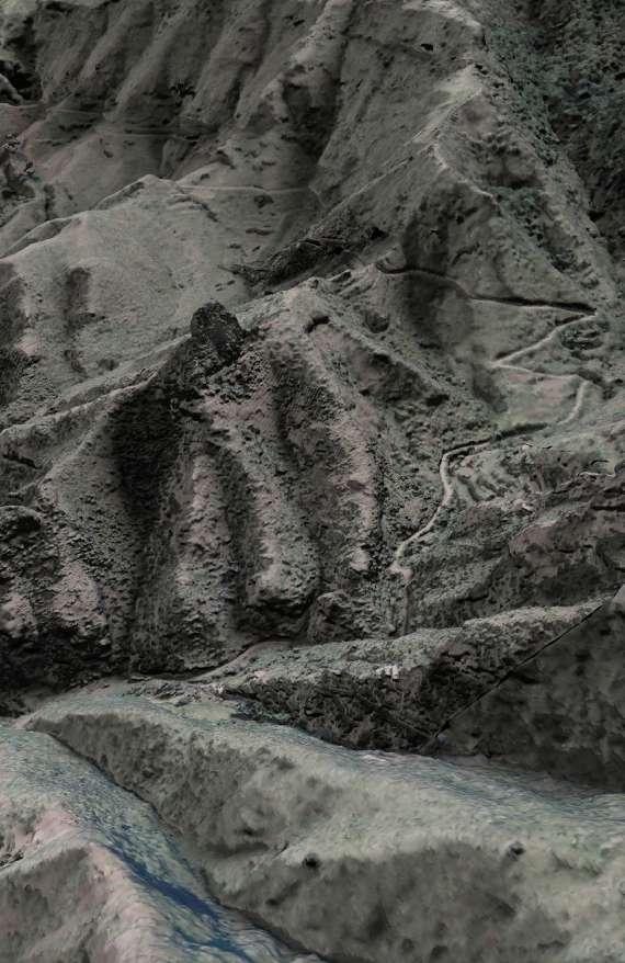
4.05 FOCUS: ASSEMBLY TRAINING , PROTOTYPING AND SITE CONDITIONING
Mock up elements will be used to ensure the high precision build required from the prefab method of construction. Elements will be tested both on and off site as well a being used as practise for assembly prior to assembly on site.
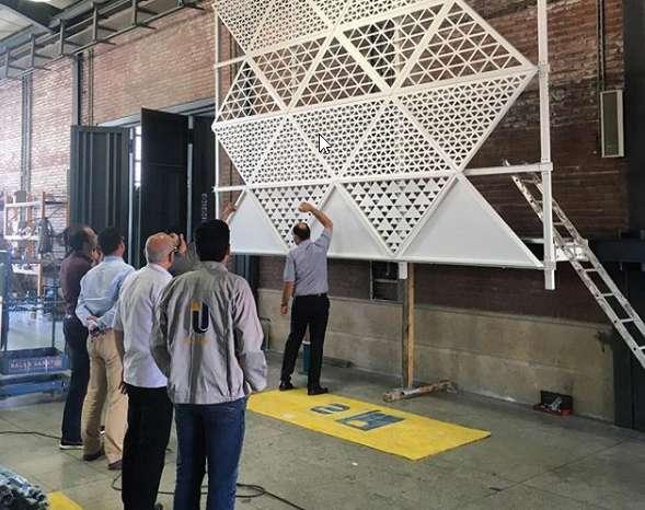
Samples and mock-ups are now more common on large scale construction projects due the necessity of testing certain elements, especially if they are bespoke or non standard elements which require further testing [A] Also a full scale mock up allows the client to view a portion of the design and the quality to be expected throughout the project. Samples can provide a coherent idea of what the finishing of the final build would look like through the application of elements such as the stone tiles etc... Mock-ups can either be one to one, which can help to test their performance more effectively and anticipate any issues during the build. Or can be scaled-down so that a larger portion of the build can be displayed and understood as a whole entity. Depending on the necessary criteria of the test, this would determine whether or not build full scale.
A mock up may also be required as part of the tender process when suppliers or products are being selected prior to an order being placed.
The mock up may also be required post selection of the materials to show compliance with the specification and therefore allow for a review of appearance and potentially further testing to be carried out. Its also possible that some suppliers may want to prepare the mock up themselves in certain areas, so as to verify their ability to produce the product to the stated specification.
The use of a mock up can be beneficial for a list of reasons, such as the following
-Potential failures of an element can be discovered through the tests that are performed and rectified to avoid similar uses during the build.
-When developing experimental components such a the inflatable panels in this case, the prototype provides assurance that the specified materials and system will function as required under a variety of conditions which can be simulated and understood using the mock up. [B]
- A mock up can help improve installation techniques prior to actual work beginning, given the time critical assembly of the prefab elements, it may be important that workers can practise assembly before the actual construction on site [C]
- They can be useful in obtaining approval from the client who may find it difficult to understand technical drawings.
Mock-ups can be either built and tested on site, part of the building itself, at the manufacturer’s premises, or at a third-parties testing facility which may have the specific technology required, such as pneumatic inflation for the ETFE panels.
The use of a manufacturer’s premises is beneficial for testing in a controlled indoor environment which can allow for faster testing, and iterations of the prototype. Also allowing for the testing procedure to be made relatively easy.
A site-built mock-up allows for the piece to be tested under the actual conditions of the site, such as weather conditions of the area, that could have unpredicted affect on the materials used in this area. [E]
If a mock-ups is required, the project documents and specifications must include precise requirements and test procedures. Test procedures should cover the specific tests, how they will be carried out, the conditions under which the test should be carried out, the qualifications requirements for pass or failure and to state whether any relevant witnesses must attend, such as designers or the client. This allows for the cost of the mock-up to be included as part of the original bid.
Prototyping and the production of one to one samples are essential when working on complex and bespoke elements such as the inflatable panels that are located on the tower. A multitude of samples would be iterated and made as part of the design process. However once completed and a design is chosen, it’s important that the panels would be tested as a unit, instead of separate elements. Therefore a series of tests would be conducted to ensure they meet the stated specification agreed on.
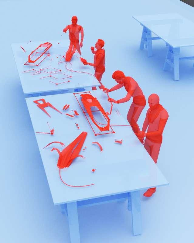
The iterative design of these bespoke ETFE panels is as much an iterative process of design as well as providing the qualitative features of a mock up. As the panels define a key aesthetic in the overall appearance of the design, its important that the client can see real size mock ups of the panel and have input if necessary into its design and appearance during its physical design phase and testing.
The unique sequencing of assembly and use of air crane implies a very time sensitive assembly of each component. To ensure the time frame of assembly is met, workers will have to train in the assembly of these pieces prior to their delivery on site. This practise will ensure that sequence of assembly should move as smoothly as possible during the delivery and reduce the amount of waiting time of the air crane.
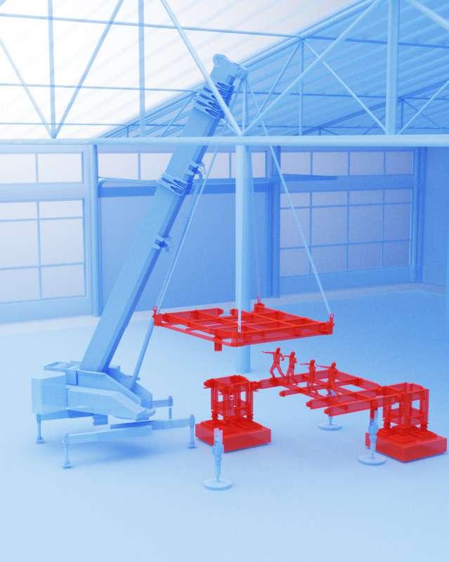
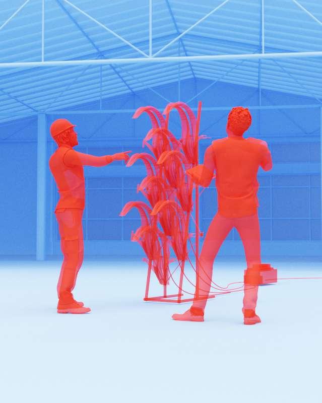
Mock ups of the facade such as the ETFE panels are tested as a portion of elements and how they interact as an entire entity so as to anticipate any potential deficiencies in the design such as the inflation of the pneumatic system. A key testing criteria would be their reaction to the data of heat recorded as this is key to the whole environmental system. A simple error at this stage could affect the entire performance of the building. If these tests are conducted during the early design stage, alterations can more easily made to the overall design so as to ensure coherence of the design. Issues of aesthetics can be also anticipated earlier that might not have been anticipated if not having seen a physical prototype prior.
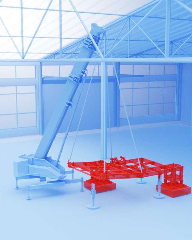
Due to the unique nature of the site, a series of full scale tests will need to be made to determine the most suitable approach of construction in terms of drilling and installing elements into the cliff. Tests will determine both feasibility and the methodology of installation so that the actual construction of the elements is done as effectively as possible. Aspects of the environment and weather will also be taken onto consideration by placing elements such a ETFE skin on site and recording daylight values.
Due to the tight delivery sequence scheduled because of the restricted use of the air crane for costing reasons. A time based assembly of each prefab element delivered is critical. Each component will have to be assembled within a certain time frame so that the crew is ready to assemble the next piece by the time the air crane returns with the next delivery. Therefore, due to the unique nature of this construction, workers will have to be trained and accustomed to assembling these components so that they can maintain the time frame required of theme during assembly. To ensure this, workers will practise this assembly before the elements are delivered to the site.
The tests and exercises can be conducted in the storage warehouse at the quarry, using a crane instead of the air crane to allow workers to get as close to the actual experience as possible. The assembled elements used in training wouldn’t be mock ups and would in fact be the actual pieces used in the construction. However mock ups could be made before hand and tested in their assembly sequence to ensure that workers can assemble them in the given time frame which could dictate the design of each element.
Factors such as weight and size would play key factors in the workers ability to assemble the pieces together.
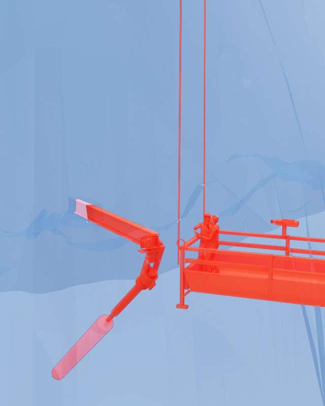
Due to the uncommon use of using ground anchors as a structural element. Significant testing of these pieces would need to be done on site.
Because the actual consistency of the rock can only be determined via scans and extracted samples, it is still possible that there could be issues in excavating the rock and how the inserted anchors hold within the rock. Site tests of the assembly process would have to be conducted beforehand to ensure the feasibility of the project. As well as determining an effective method of work sequence so that the elements can be assembled as safely and quickly as possible. All experiments and issues discovered in this process would significantly reduce the time cost compared to these issues being discovered whilst under construction.
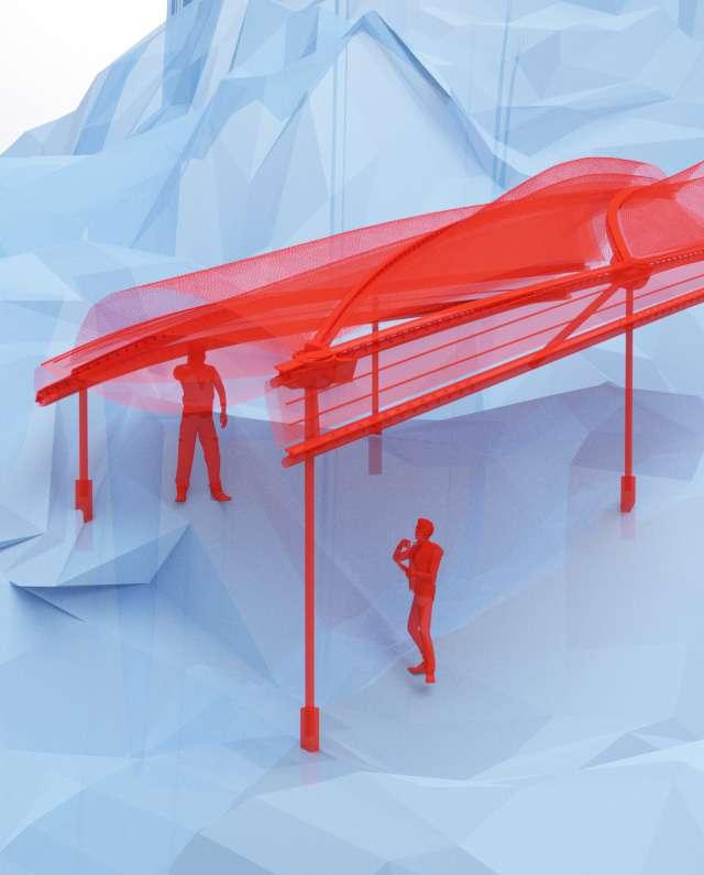
Elements of the design that are dependant on the particular environment such as the patterned ETFE pillows, would need on site testing to ensure that the system works under the particular site conditions. Aspects such as the angle of daylight and various times of year would require for the piece to be left on site for as long a period of time as possible. Therefore this experiment would need to be conducted as part of the initial design phase or even in prior testing so that architects are certain the system works in this particular environment.
MOCK UPS AND SAMPLES
4.06 FOCUS: COSTING OF CALCULABLE PORTIONS OF THE PROJECT
This page does not attempt to predict the total cost of the building due to the bespoke nature of the fabricated elements as well as the delivery system a precise number cannot be calculated without further specialised consultation. An estimation using standard costing methods such as solely referencing ‘Spon’s Architct’s and builders guide book‘ would be inaccurate in this case and is only consulted for certain portions of the building. Therefore this page attempts to estimate the cost as accurately as possible for specific costs related to the core nature of the project, such as the delivery method. Costs that are calculable from the existing model such a the structure and skin are done as precisely as possible. Whereas the use of the Spons reference book is a very broad approximation as the cost model does not match this particular project, it only serves as a consideration of cost for certain elements.
Other unique costs which are important for the project would be the excavation of the rock and the placing of anchors. However these costs vary significantly depending on location and site so could not be calculated.
The workforce employed for construction is also significant, due to the high complexity of the design, working at height, installation of ETFE , air crane delivery and assembly of the primary structure. Its doubtful that the island of Tenerife will have professional workers trained to the level required of the build. Therefore specialised workers may have to be imported from Spain which would reuslt in additional cost of housing them and so on. If researched further as to a suitable workforce, enquiry would be made as to the contractors used in the construction of the ‘Auditorio‘ Calatrava building located in Santa Cruz, 4km from the site. This construction would have required a more specialised workforce then other builds on the island.
Operating and rental cost
TIME AND COST CALCULATION
UNLOADING AND LOADING
Trained loading and unloading times, prefab elements (variance on size) 2 to 10 min
min unloading loading journey: 240 seconds max unloading loading journey: 1200 seconds
(Approximate time based on Aiguille Pipe Construction
Crews are on standby either end with the components ready to unload and load as soon a the helicopter arrives, trained in time trial to minimise time. A max and min time has been given to account for error.
Ascent and descent included in unloading loading time. Assembly time post delivery separate to unloading time’
DISTANCE TRAVELLED
Distance from harbour to site: 4300 metres
Cruise speed: 47 m/s
Rate of climb:6.75 m/s
Time = distance/speed
4300/47=91 seconds travel (variance with wind and ascent)
JOURNEYS
66 air-crane trips for primary structure
66 for floors 14 for pods 24 for skin structure
The rest of the journey are done by cable crane for materials, walls, anchors etc..
Total journeys 170
TOTAL TIME
Min time: (240 unload-load + 91 travel + 200 for precise placement) x 170 journeys x 2 return
= 180540 seconds
50 hours
Max time:(1200 unload-load + 100 travel + 300 for precise placement) x 170 journeys x 2 return = 544000seconds
151.1 hours
COST
Min cost based on time usage: 50 x 5000= 250 000 € Max cost based on time usage: 151.1 x 5000= 755 000 €
The calculation was done to show the importance of training in assembly of the components beforehand to reduce the time of loading and unloading as this accounts for the vast majority of the delivery time in this case and therefore significant cost. The cost is an approximation based on the times and cost of air crane logging sourced online. However cost of delivery of the sky crane to the island hasn’t been included and the actual costing of renting would be agreed before hand via a set contract of days instead of hours as the operation would not be running 24 hours a day due to lighting and restricted number of workers available and
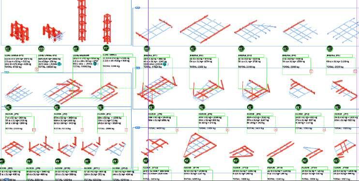

The below figures are taken from ‘Spon’s Architects and builders’ price book’ for a building cost model of a hotel in the UK, Manchester. The costing will be used only to gain an approximation of cost for specific portions of the design, as the actual cost is linked to the method of prefabrication which would vary from this model. The price would also obviously vary based on the country of construction, which in this case is the island of Tenerife. In addition the cost model of the Manchester hotel is 8 400 m some of the costs listed are not calculated per m2 but as sub total for that building, these are notified as ‘nr’ in £ per m2 The total m2 of this project is 3972 m2 therefore as an approximation these set costs for are halved from the Spons number. The rest of the calculations are based off of rate per m2 for a hotel using the m2 of this project.
The costing below does not cover every element listed in the Hotel costing section, but rather I have included a series of key feature that can calculate from my model. Therefore the final cost is not representative of the overall cost, especially given the nature of the prefab which would be a different cost model. But rather these calculations serve as an approximate cost for these specific areas.
ACOUSTIC METAL STUD PARTITIONS
WC AND CUBICLES
INTERNAL DOORS
STONE FINISH
CEILING FINISH
Therefore coming to around 323
€ (vary based on supplier and transport)
The costing consists solely of the cost of the actual beams themselves, additional cost of delivery to the island via ship, installation and assembly by workers structural engineering and permits would be inaccurately calculated at this stage. Also the unique build and assembly joints do not allow for a typical installation cost to be calculated.
As sourced form ‘continuing education centre architecture + construction’ ETFE ranges between $125 and $185 per square foot installed. Taking the max cost due to complexity of installation and location, converting into metres and Euros this comes to about 1794 € per metre squared.
SANITARY FITTINGS
FURNITURE AND FITTINGS
SERVICES AND EQUIPMENT (kitchen etc..)
DISPOSAL INSTALLATIONS (pipework, waste..)
HOT AND COLD WATER INSTALLATION
MAINS AND SUB MAINS DISTRIBUTION (electrical)
ELECTRICAL SUPPLIES TO MECHANICAL PLANT
INCOMING GAS SUPPLY, STEEL PIPEWORK...
PUBLIC LIFTS (2)
SERVICE LIFTS (2)
BATHROOM PODS (specialist
The cost will vary from the price depending on the complexity and cost of the inflatable panels in the tower which should contain a different form of costing as applied for the rest of the pillows. Also the use of the patterned ETFE for daylight control will vary from this price due to it being a bespoke design. Variance of cost will also apply due to its location and difficulty of access.
The actual number would be larger as not every element was taken into
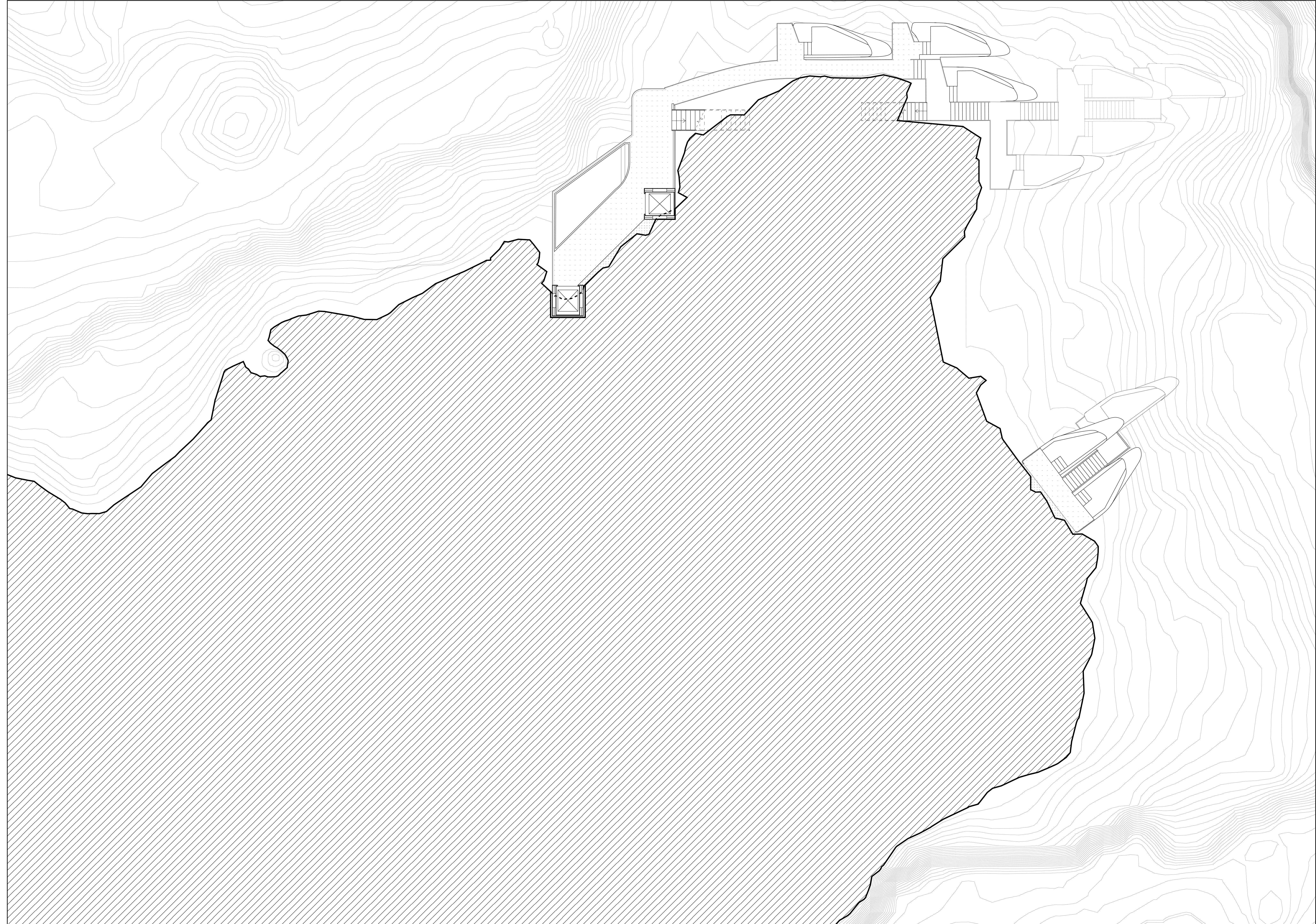
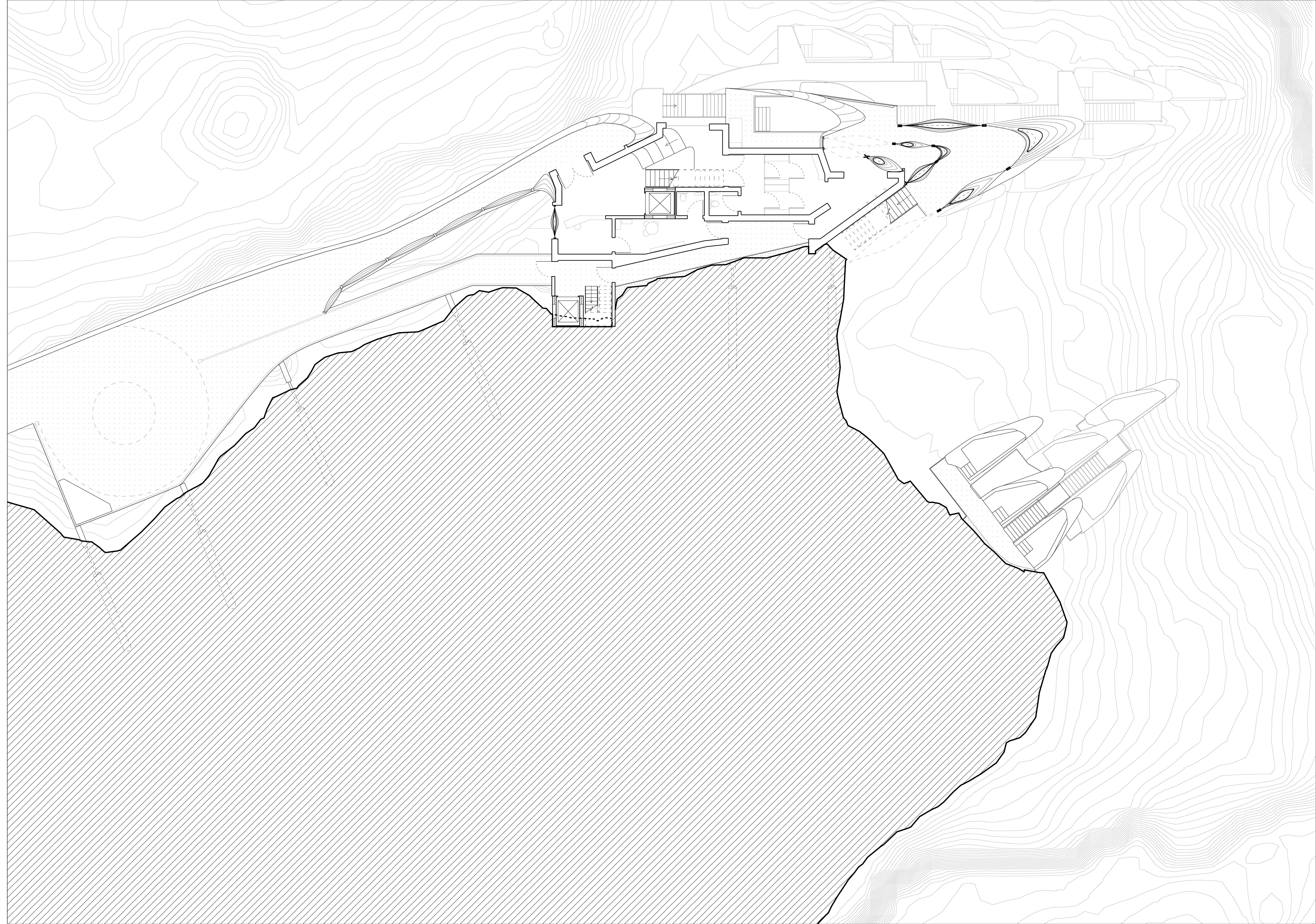
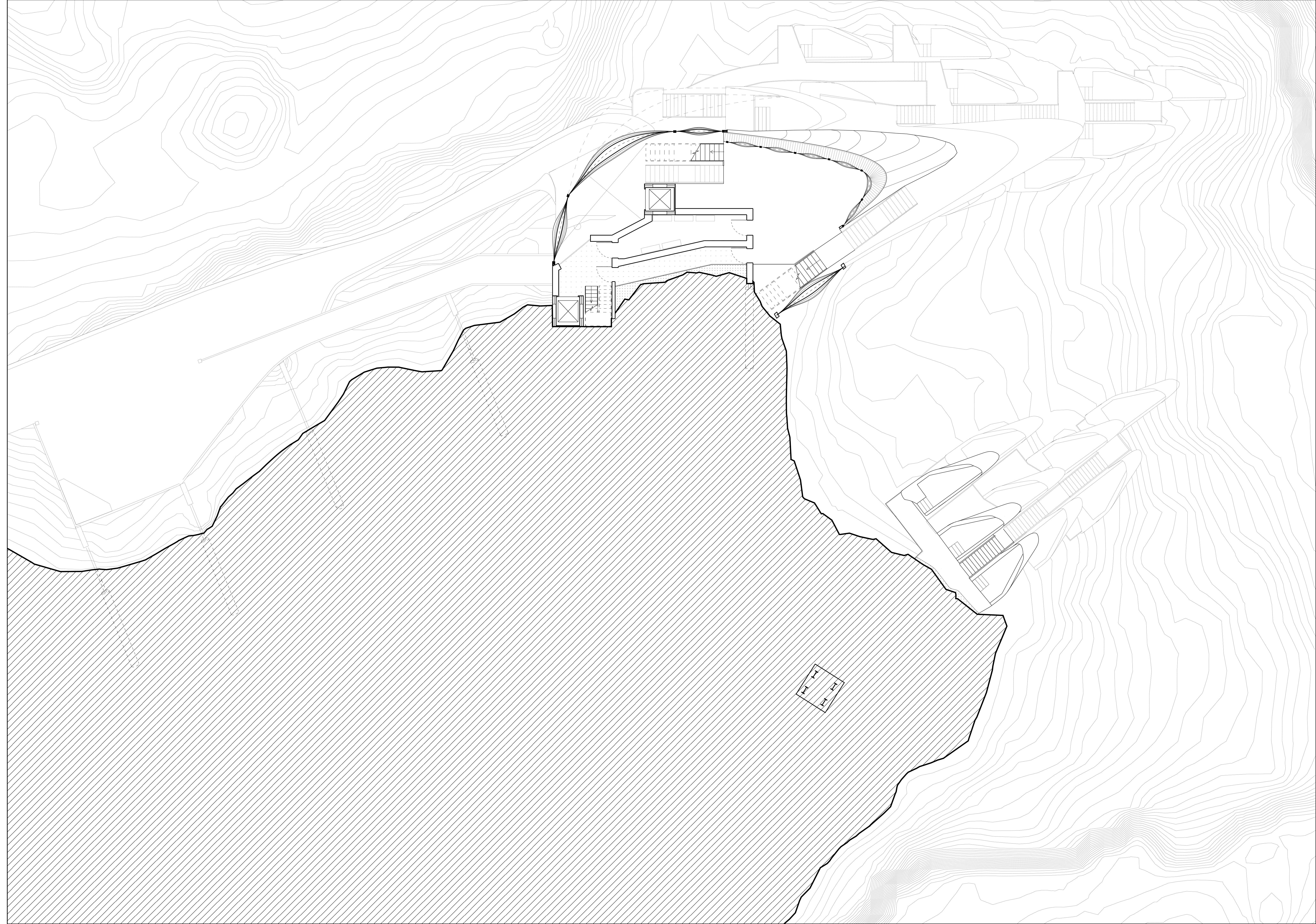
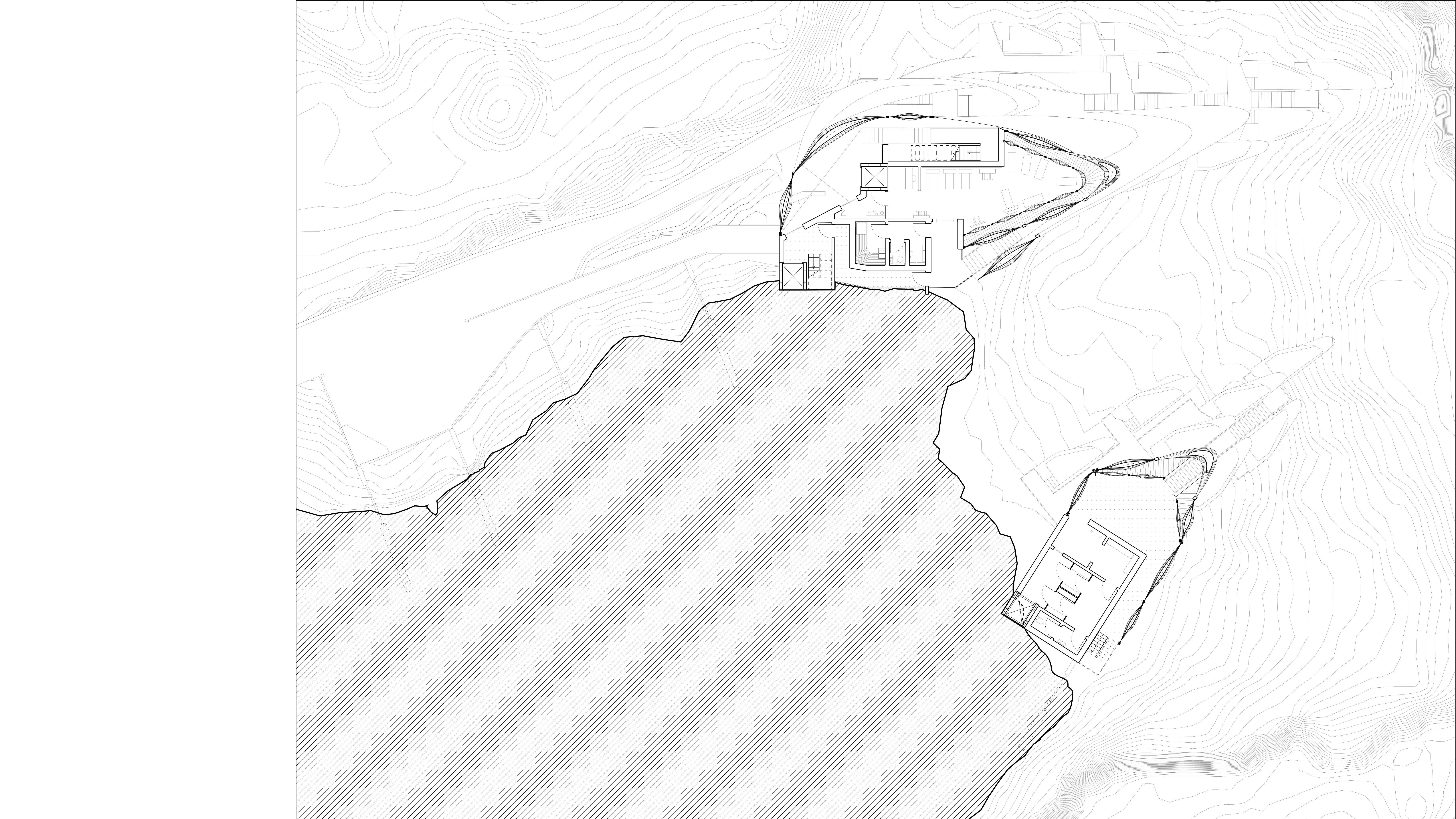
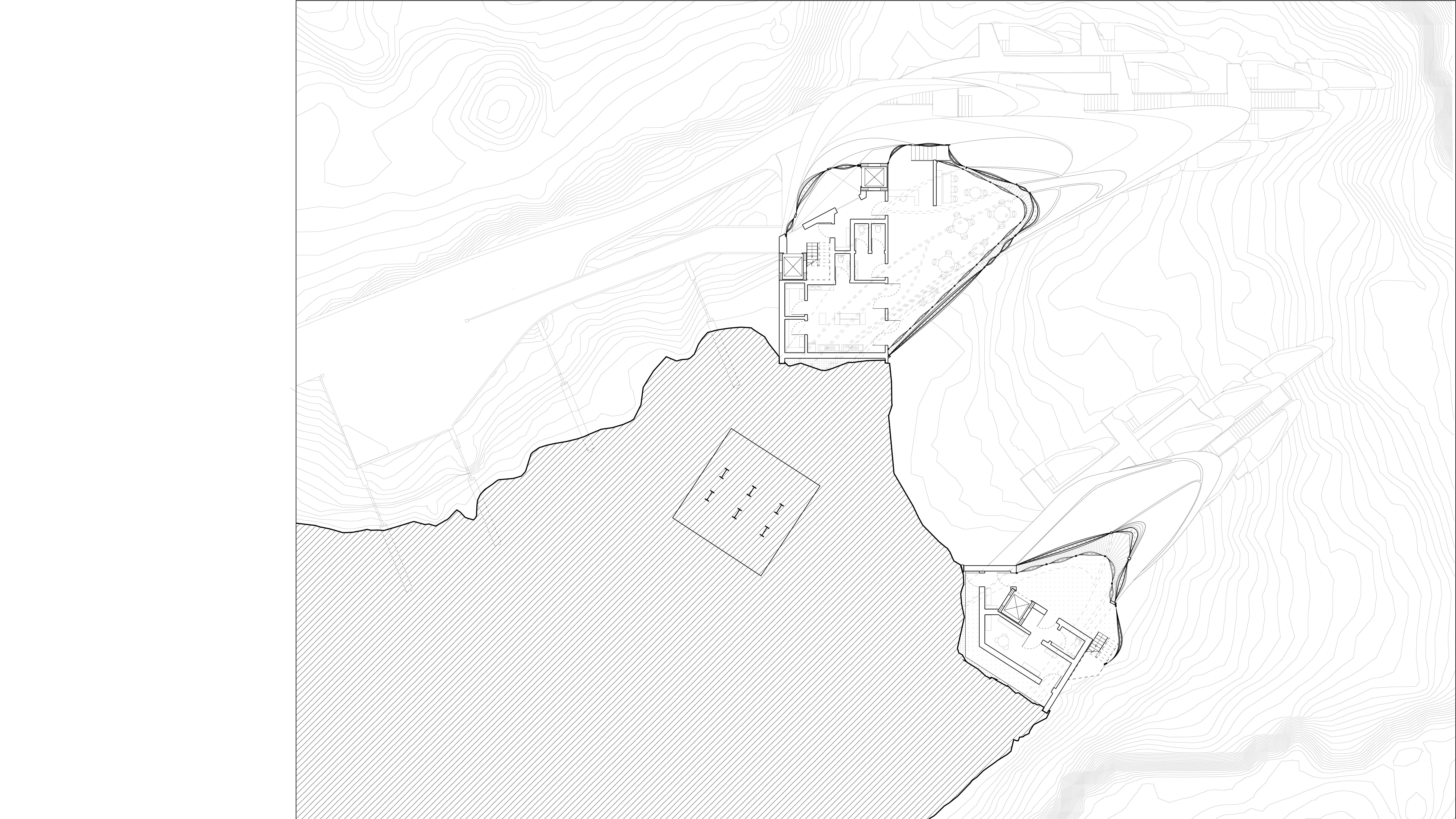
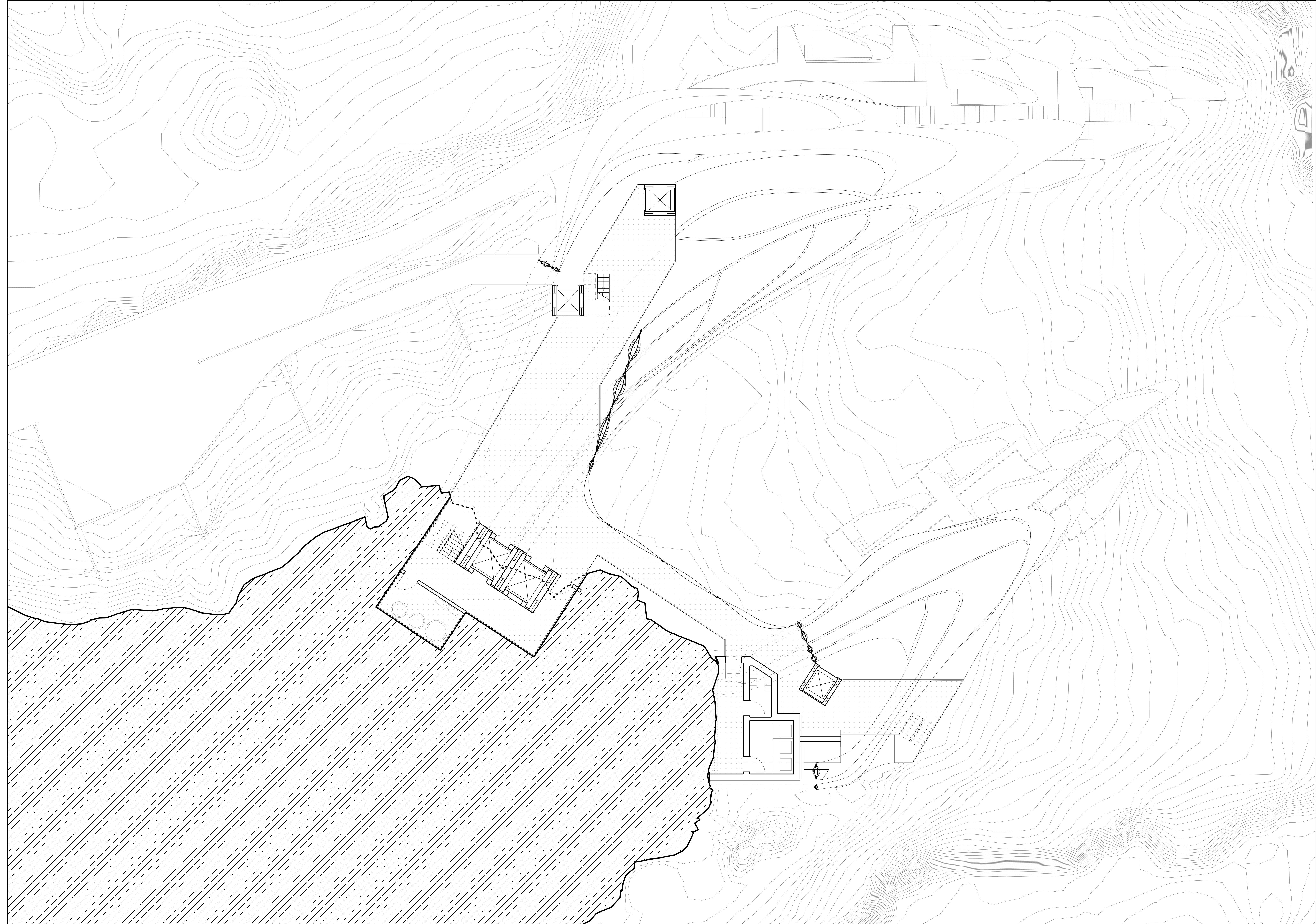
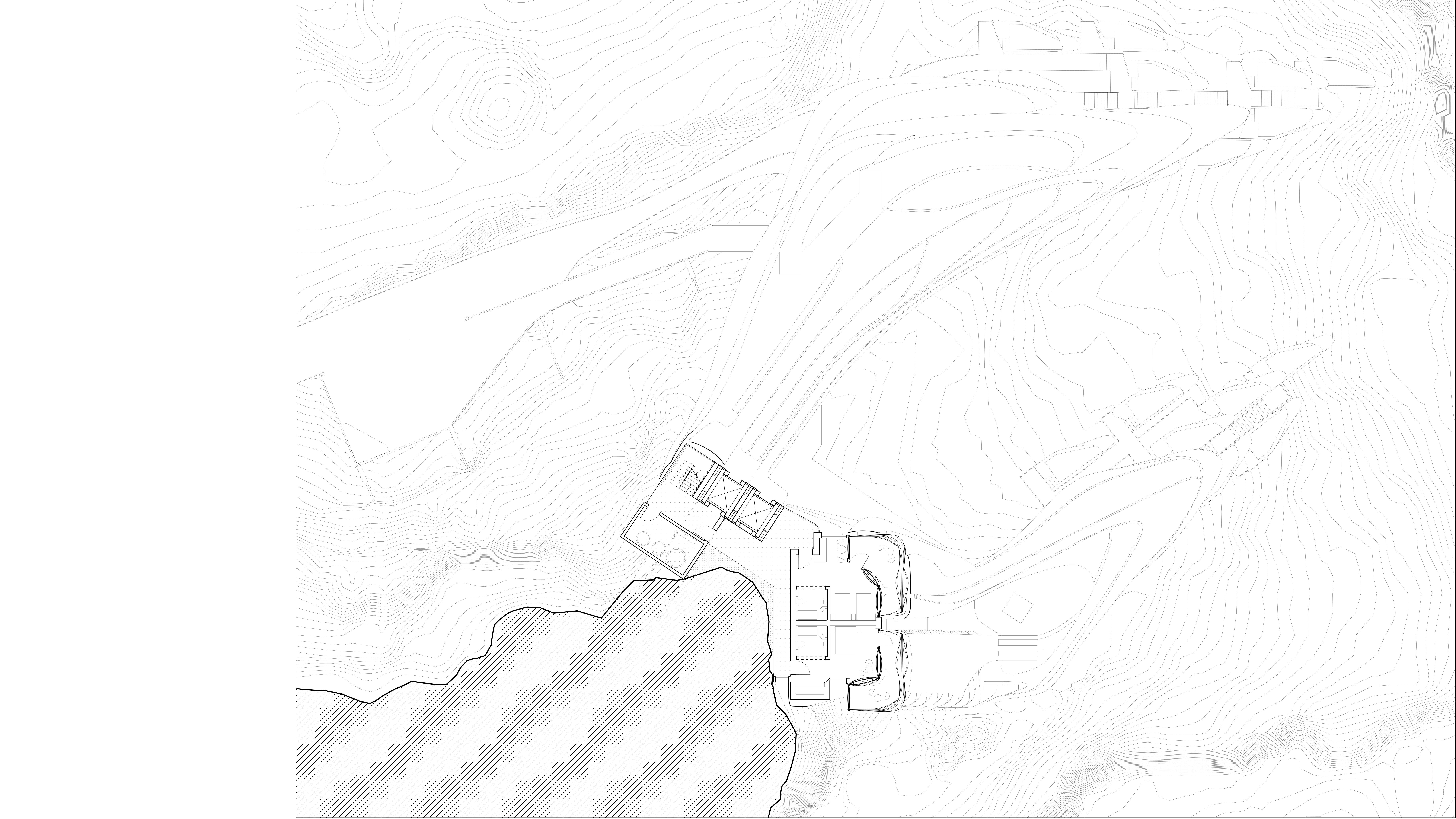
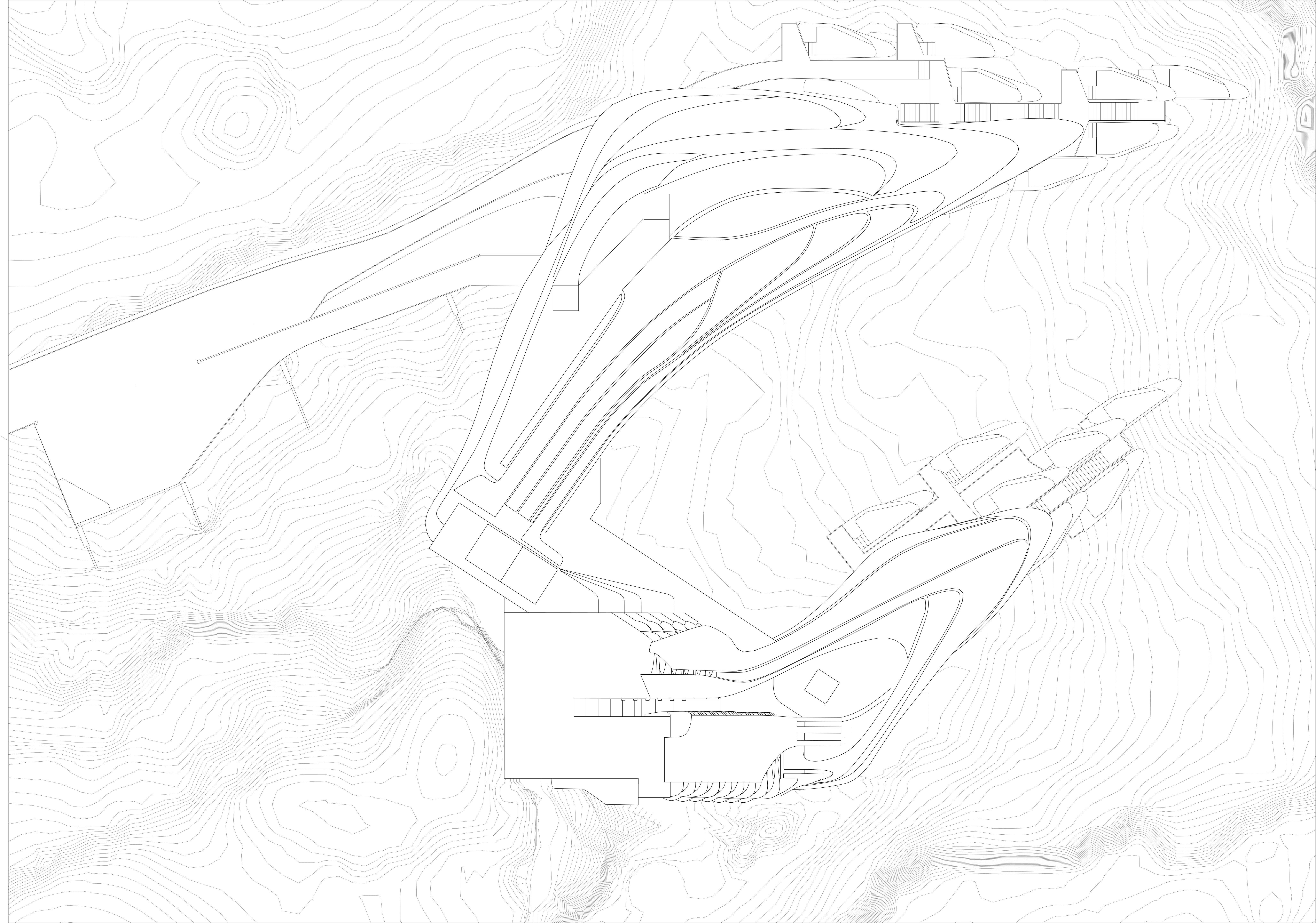
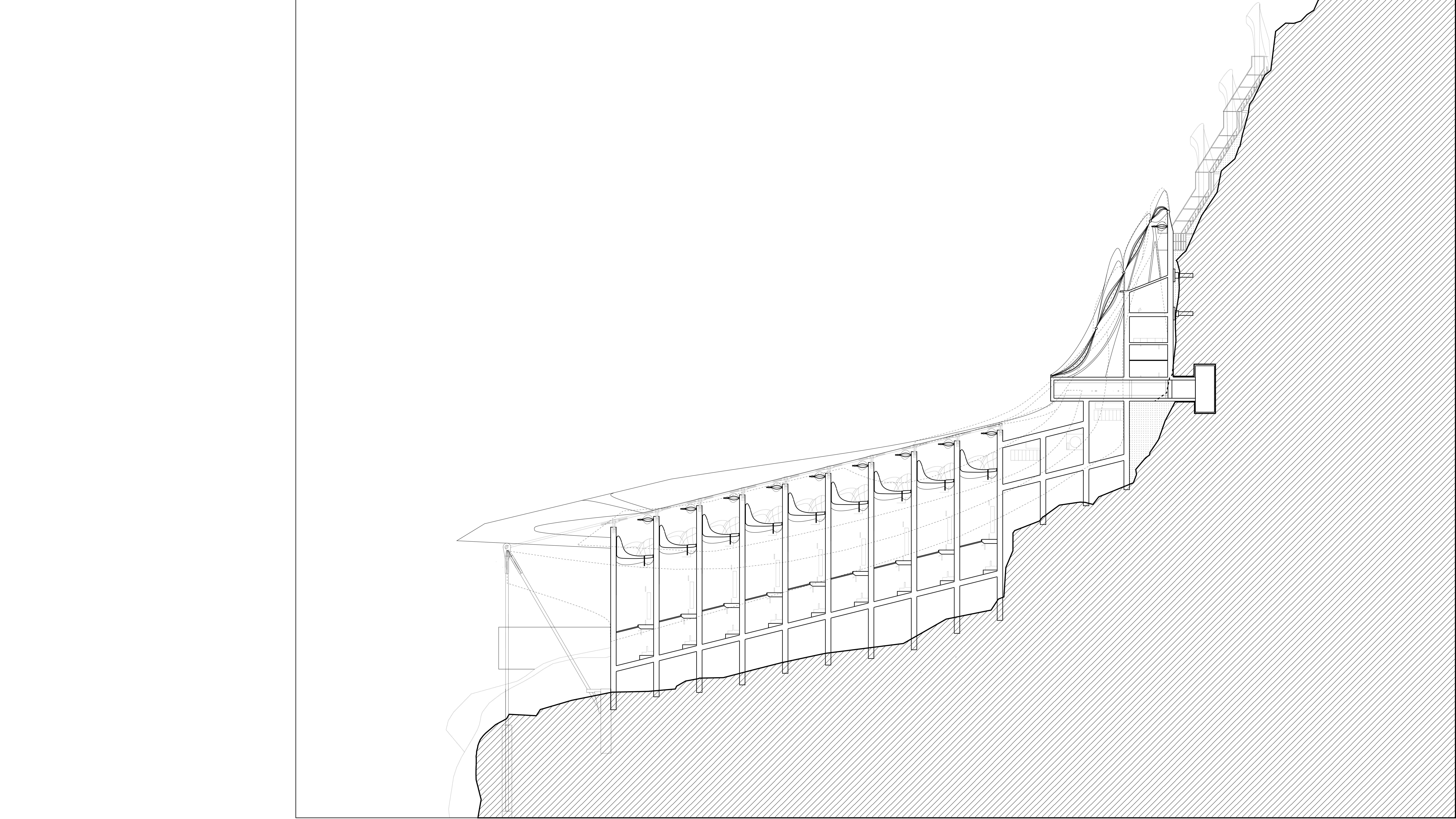
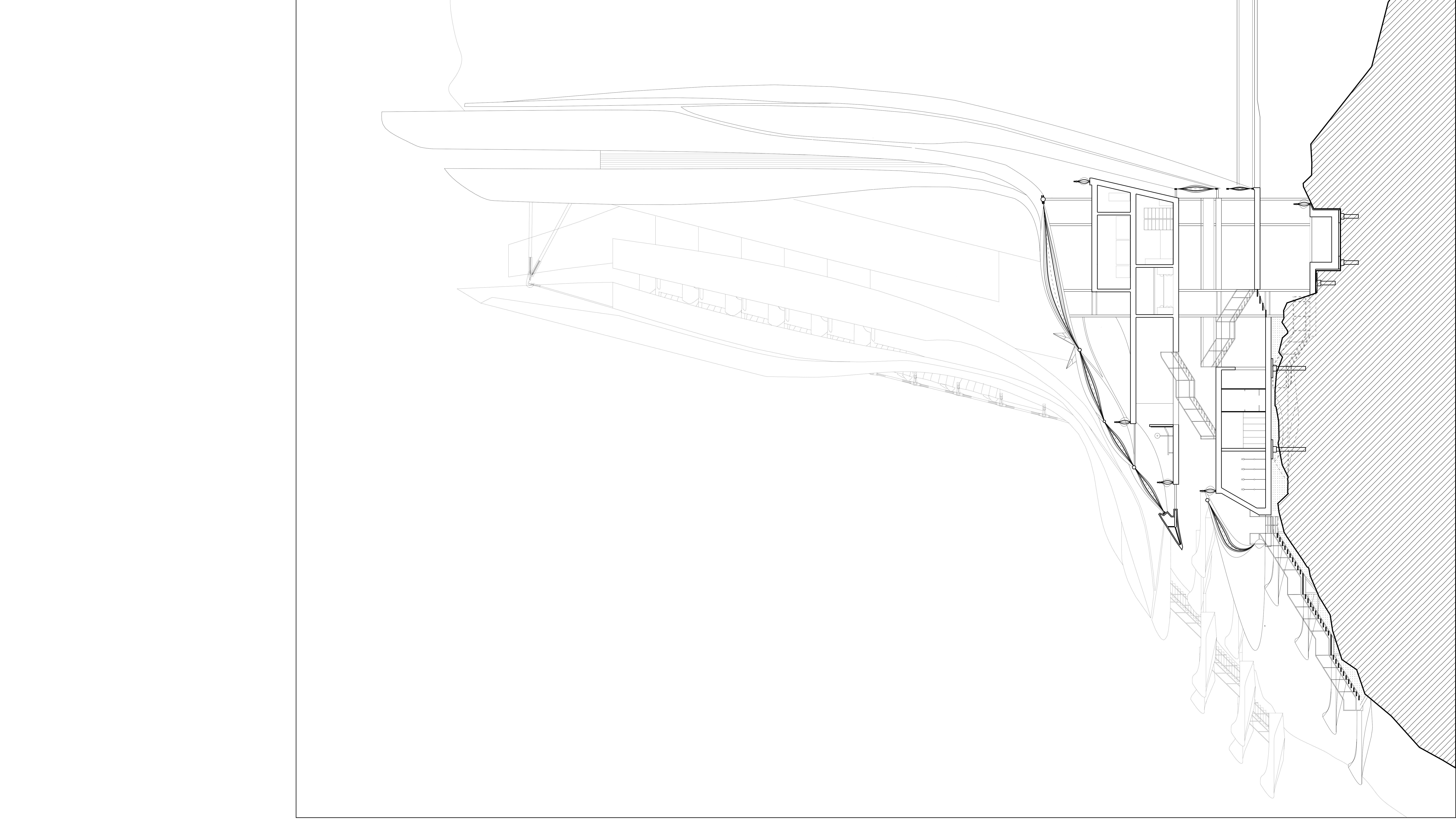
windy.com( Accessed 03/20)
https://www.alamy.com/people-enjoying-a-sunbathing-in-la-caleta-beach-with-the-san-sebastian-castle-a-fortress-in-la-caleta-island-in-the-background-cadiz-spain-image260081713.html( Accessed 04/20)
https://www.advartis.uk/ ( Accessed 04/20)
https://www.elperiodico.com/es/ ( Accessed 04/20)
https://tangible.media.mit.edu/project/aeromorph/( Accessed 03/20)
https://www.designbuild-network.com/projects/media-tic/ Accessed 03/20)
Part M access to and usage of building Accessed 04/20)
https://www.edenproject.com/ ( Accessed 04/20)
https://www.archdaily.com/13358/the-therme-vals Accessed 04/20)
https://www.hydroreview.com/2017/04/01/technology-allows-hydropower-construction-at-inaccessible-sites/ ( Accessed 04/20)
http://www.pilotspost.co.za/arn0000815 Accessed 04/20)
https://www.wyssenseilbahnen.com/en/valentini-mobile-cable-crane/ ( Accessed 04/20)
https://www.researchgate.net/figure/Designing-of-knuckle-joint_fig2_323393528 Accessed 04/20)
http://www.pilotspost.co.za/arn0000815 Accessed 04/20)
https://en.wikipedia.org/wiki/Safety_harness Accessed 04/20)
Part B fire safety Accessed 04/20)
https://www.youtube.com/watch?v=c7pUpPHHEaE ( Accessed 04/20)
https://www.airliners.net/photo/Erickson-Air-Crane/Sikorsky-S-64F-Skycrane/725875 Accessed 04/20)
https://www.alamy.com/stock-photo/rockbolt.html Accessed 04/20)
https://www.knapp-verbinder.com/en/products/prefab-walls/ ( Accessed 04/20)
https://www.constructionspecifier.com/prefabricated-wall-panel-system-facilitates-passive-house-certification/ ( Accessed 04/20)
https://aluminiumandalloys.com/the-uk-aluminium-extrusions-market/ ( Accessed 04/20)
https://www.arch.rpi.edu/2013/12/saunders-robofold/ Accessed 04/20)
https://www.to-experts.com/en/projects/detailview-references/maintenance-of-etfe-cushions-and-inner-ceiling/ Accessed 04/20)
https://www.alamy.com/stock-photo-workmen-installing-the-etfe-pneumatic-panels-which-form-the-new-roof-75952647.html Accessed 04/20)
https://www.stylepark.com/en/news/close-to-the-wind Accessed 05/20)
https://gizmodo.com/a-tour-of-the-futuristic-roof-on-californias-new-high-s-1641494500 ( Accessed 05/20)
https://gizmodo.com/a-tour-of-the-futuristic-roof-on-californias-new-high-s-1641494500( Accessed 05/20)
https://www.eco-sources.com/products/160w-12v-monocrystalline-flexible-lightweight-ultra-thin-solar-panel-charger-with-mc4/( Accessed 05/20)
https://www.researchgate.net/figure/UV-B-radiation-map-of-Spain-Map-showing-the-annual-average-daily-UV-B-radiation-J-m-2_fig2_256705183( Accessed 05/20)
https://www.ehstoday.com/safety/media-gallery/21920111/top-10-most-dangerous-jobs-of-2019/slideshow( Accessed 05/20)
https://iibec.org/oshas-drones-inspection/( Accessed 05/20) Accessed 03/20)
https://www.grasshopper3d.com/photo/triangular-facade/next?context=album&albumId=2985220%3AAlbum%3A1986304( Accessed 05/20)