
GREASE PRODUCT CATALOG


2 | gpreeves.com

© 2022 | 3 TABLE OF CONTENTS ..............................................................................................................................................................24.......................................................................................................................................................4...........................................................................................................................................7..................................................................................................................................................8...........................................................................................................................................9.......................................................................................................................................10.................................................................................................................12...................................................................................................................14....................................................................................................16................................................................................................17....................................................................................................................18...............................................................................................................19........................................................................................................20..............................................................................................................................................21...............................................................................................................22.......................................................................................................................23..............................................................................................................................26..........................................................................................................................................28............................................................................................................................................30....................................................................................................................................................32...................................................................................................................33........................................................................................................................34........................................................................................................................35...........................................................................................................................36................................................................................................................................................37.......................................................................................................................................38.............................................................................................................................................39.......................................................................................................................................40............................................................................................................42...............................................................................................................44.......................................................................................................................................46...........................................................................................................48.............................................................................................................49...................................................................................................................50................................................................................................................................51............................................................................................................................52..................................................................................................................53.................................................................................................................................54................................................................................................................................55.........................................................................................................................................56...........................................................................................................................................58.........................................................................................................................59 Introduction About DispenserUs CustomProductApplicationsTypesOfferingSolutions Source Single Post Ram Pumps (GSP) Dual Post Ram Pumps (GDP) Narrow Dual Post Ram Pumps (GNDP) Miniature Dual Post Ram Pumps (GDPM) Manual HighAutomaticReservoir/RegulatorsReservoir/RegulatorsPressureReservoir/Regulators Preparation Grease Filters MPR Series Pressure Regulators GPR5000 Series Regulators GUS Dispensers GSS/GSSM Dispensers GPMD Dispensers AA ProgressiveRotoMeterDispensersScrew RotoMeter End Points Low Flow Dispense Valves High Flow Dispense Valves Handheld Dispense Guns Zone CustomG-Force™SprayExtrusionValvesNozzlesNozzlesNozzlesNests,Nozzles, & Tooling Accessories Confirmation Device Breakdown Pressure Sensors Volume Confirmation - Mechanical Volume Confirmation - Ultrasonic Flow Confirmation - Inductive Controllers Dispense Control Hub Standard AA Controllers Customized Control Packages Reference ACE Cartridge Valves EzBleed™ Bleed Plugs Dispense Patent Grease VolumeVolumeConversion Chart
While this is still a popular product of ours, our constant innovation over the past 50+ years has led to the expansion of our product offering. In the mid 1980’s, our product line expanded to include various non-conveyor chain lubrication devices, and today we offer a large selection of material pumps, dispensers, accessories, and Sincemore.wewere founded, our products have helped thousands of companies improve their products and assembly processes through accurately measuring and dependably dispensing precise amounts of oil, grease, and other assembly fluids, such as adhesives and sealants. We understand the frustration of trying to put together pieces that weren’t made to go together, which is why we offer every product you may need in your systemputtingyoursystem,dispensingsimplifyingprocessofadispensingtogether.
4 | gpreeves.com GP Reeves was founded in 1971 by Gordon Reeves in Grand Rapids, Michigan. At our founding, our focus was primarily on lubricators for assembly conveyor chains.
In addition to our standard product line, we can modify any product to meet your specific need, or design a fully custom product if needed. With multiple patents and over 200 years of combined experience under our belt, you can rest easy knowing your dispensing process is in good hands. History
GP Reeves is a leading manufacturer of dispensing equipment. We engineer and build all aspects of a dispensing system from pump to nozzle; plus we have standard and custom options available for materials such as grease, oil, adhesives, sealants, 2k and more.
ABOUT US Our


© 2022 | 5 We have happy customers in almost every manufacturing industry across the globe including aerospace, agriculture, automotive, consumer products, energy & natural resources, heavy equipment, medical, recreational vehicles, and more. A map of our current customer base plus some of the companies using our products is shown. Our Customers Global NetworkDistribution Our global distribution network spans 4 continents and 17 countries currently and the network is continually expanding. For more information about finding a distributor in your area, or if you’re interested in being a distributor of GP Reeves products, reach out at (616) 399-8893.


6 | gpreeves.com Industries Served GP Reeves is a leading global provider of engineered dispense systems and manufacturing solutions. We have been applying our experience to a variety of industries and environments for over half a century. Not only do we produce dependable and reliable dispensing systems, but we can also engineer and build custom equipment to meet any needs. GP Reeves offers a complete line of grease, oil, ambient, and heated material dispensing equipment and automation that can be utilized in a diverse range of applications and industries. Oil, Gas, & BatteryMiningMedical Renewable EnergyHeavyAerospaceEquipment Recreational Vehicles Automotive Consumer Products Food & Agriculture 1 2 3 4 5 6 7 8 109 MaintenanceLubrication LubricationAssembly DampeningVibrationLubrication MechanicalLubrication SafetyLubricationRelated Machines or equipment that are lubricated to prevent failure/downtime How Critical Is Your Grease Application? What Is Your Number? (#1 is not critical, #10 is extremely critical) Material – What is the name of the material being dispensed? Manufacturer & Product # – What size container will the material be purchased in? Cartridge, 5 gal, 55 gal, metric, etc. – What is the desired shape of the material? Bead, Film, Daub, Dot, etc. – What is the volume or amount being dispensed? – What is the tolerance of the dispensed material? – How many locations require material (total for system and on each part)? Process – How critical is the application? (use chart above) – What is the overall cycle time and dispense time? – Will this be installed on an existing piece of equipment? Specifications – Is volume verification required? If so, via HMI, Info System, stack light? – Are there any special plant specifications? I.E. PLC, HMI, Pneumatic or Electrical components? Components that are lubricated to assist in assembly only. Components that are lubricated to prevent vibration. Components that are lubricated for life. Components that are lubricated for life that causes safety concerns if not lubricated properly. Application Questions
DISPENSER TYPES
© 2022 | 7
There are several types of material dispensers available, the most common types being positive displacement and timed. Each type has it's perks, but when it comes to precise dispensing, we strongly recommend the use of positive displacement dispensers. Unlike timed dispensers, the exact volume of material dispensed doesn't vary from shot to shot, no matter the external variants (such as temperature or viscosity). Positive displacement dispensers utilize a piston, or something similar to push out material equivelant to the volume of the piston, ensuring an accurate dispense every time. Timed dispensers will dispense for a set amount of time, but the exact volume can be impacted by external variants.
Recommended: Positive Displacement Dispensers
Nearly all GP Reeves dispensers utilize some sort of positive displacement dispensing. Many dispensers utilize a piston that works by transferring material under pressure through self-actuated or powered valves into and out of a measuring chamber. The powered piston controls the transfer volume and the transfer (dispense) is directly proportional to the piston area and piston travel. Our RotoMeter series utilizes various types of rotational dispensing in the form of gear, peristaltic, and progressive screw pumps.
Not Recommended: Timed Dispensers
Timed dispensers function like a faucet and require frequent re-adjustment and constant monitoring. Timed dispensers cannot be trusted to repeatedly dispense identical amounts.
Positive displacement dispensers can be adjusted and set once. Their positive displacement piston stroke dispenses like a syringe. Positive displacement dispensers can be trusted to repeatedly dispense identical amounts regardless of external temperature or material viscosity.
Material's flow characteristics are often unpredictable meaning timed dispensers are not capable of accuracy and repeatability. The exact volume of how much is on the part is an unknown unless a weight is measured of each part before and after.
Timed dispensers work by moving material under pressure through an “Off-On” valve that is opened and closed by a solenoid valve controlled by a PLC or electronic timer. Pressure regulators and adjustable orifices are sometimes added to control flow rate.


Standing Desk Leg: This automated system served two purposes, lubricating the inner diameter of the leg while tapping holes in the sides. The system included vacuum tubes to prevent mess while reducing the amount of equipment in their process.
The above photo shows a messy, brushed on application of grease to an HVAC part on the left, and what our custom nesting was able to accomplish on the right. Not only does the application look cleaner, but you can be assured that the precise amount of material is in the correct spot every time. Our portfolio of work is constantly evolving, we would love to chat with you about your application!
We have been spent over half a century perfecting material dispensing. Our experience ranges over variety of industries and environments. Not only do we produce dependable and reliable dispensing systems, but we also engineer and build custom equipment to meet your specific needs, no matter the industry. Prior to using our equipment, customers are often applying materials by hand which yields not only time loss but wasted material. Fully automated dispensing systems like the one below provide the highest level of precision expertly designed for your specific part.
8 | gpreeves.com
A1C Monitor: This application ensured battery tabs on both sides of the medical device were properly greased to aid in assembly and prevent corrosion long term. Custom nesting was utilized to ensure a precise grease application.
APPLICATIONS
Dishwasher Motor: The customer approached us to lubricate a dishwasher motor pump mounting plate to aid in assembly. We created a custom system that rotated the part allowing us to spray material around the entire outer diameter.
Before – Messy – Wasted Grease – Inconsistent Application Our Application – Precise – Accurate Volume – Uniform Dots – Repeatable


Inductive
G-ForceEndSensorPoint:Nozzle Example
Dispensers
OFFERING
Preparation
PRODUCT
Our wide variety of standard products range in capability from pumping material to accurately and precisely dispensing it onto a part. The vast selection of products we have are compatible with grease, oil, adhesives, sealants, two-part materials, and more.
On top of the many standard products we offer, we also specialize in custom part nesting, nozzles, or entire custom systems with or without automation.
Source – Includes material pumps, reservoirs, and other starting point equipment.
– Includes material filters, pressure regulators, and patented air removal technology.
– Positive displacement dispensing ensures repeatable accurate dispensing no matter the viscosity, temperature, or other external variants.
– Continuous flow dispensers are available for most materials in varying speeds and options..
– Preparing material to be dispensed is essential to protect your system and your final part.
– Analog mechanical, and ultrasonic sensors are available with optional digital readout.
– Devices can dispense a beads, dots, sprays, or something completely custom.
A complete system, standard or custom, includes parts from every category listed. This catalog provides details on the products available in each section and what will work for different materials.
– Options that pump material from the original container as well as reservoirs are available.
© 2022 | 9
Confirmation Devices – Includes devices that confirm volume, flow, or pressure for all materials.
– Devices are used as a final check for material movement and are essential for critical applications.
– Single-shot dispensers have a volume range of 0.001 to 1086 cc, with every size option in between.
End Points
– Includes a variety of nozzles and valves to meet specific application needs.
– Determining source product is based on material and the container it comes in.
– Includes a variety of ultra-precise, positive displacement dispensers.
Source: GDP RegulatorPressureandMaterialPreparation:FilterMaterial
AA8Dispenser: Confirmation Device: Flow System
– Features including speed, monitoring, and air removal technology.


SOLUTIONSTURNKEYCUSTOM
10 | gpreeves.com
Automotive Cup Holders: The system to the right sprayed a dry lube material onto cupholders for a popular minivan. The material is invisible to the naked eye, but visible with UV light, our system had a smart vision system that didn't release the parts until an accurate dispense was confirmed. Dual sides allowed for reduced downtime in the application process.
Sunroof Rails: Sister systems sprayed grease onto the sunroof rail and mech pieces in an SUV.


Dishwasher Rotating nest paried with multipe plray nozzles parts received 360º spray of material.
© 2022 | 11
Driveshaft Spline (Left): System utilized G-Force nozzle to spray the inner diameter of multiple driveshafts with grease.
Motor:
ensured
Transaxle Housing (Above): Robot applied a bead of RTV to multiple transaxle housing parts ensuring a proper seal.
Automotive(Below): Rotating robot applied material onto varying automotive parts.


12 | gpreeves.com SINGLE POST RAM PUMPS (GSP) (Optional)ValveSolenoidCircuitRecirculation(Optional)ControlValveDepressurization(Optional)Panel(Optional) Features and Benefits – Reliable and dependable – Pumps all the way to the bottom of your pail – Keeps pump suction “off the floor” GSP series air-operated pumps are engineered for production material supply. Single post ram assures a reliable supply with material that doesn’t seek its own level. All pump options include pump, inductor seals, single post ram, ram control valve, pump air pressure regulator, and ram air pressure regulator. These pumps will work with NLGI 00-3 materials and are available in a variety of configurations. Shown GSP20-120B60NPNas Add H after any inductor seal code to add a heated inductor assembly for use with thicker materials. See example part number above. GSP Ram CODE RAM STYLE MAX HEIGHT OF PAIL / DIAMETER (ID) GSP Single Post Ram 27” / 15.75” * Air inlet has relief valve at specified pressure Inductor Seal PAIL SIZE SEAL CODE SEAL MATERIAL DESCRIPTION 18 kg, 35 lb A Dual Lip, Polyurethane 120 lb, 16 gal B 25 kg C 35 kg D 50 kg, 61L E 35 lb H Aluminum Assembly with Single Neoprene O Ring Seal 50 kg L Dual Lip, Polyurethane 37 lb M Pump Motor CODE RATIOBOOST MAXIMUM OUTPUT PRESSURE OUTPUTMAXIMUMFLOW 20 20:1 3,000 PSI at 150 PSI air 2,100 cc/minute 22 22:1 2,200 PSI at 100 PSI air 1,500 cc/minute 50 50:1 3,000 PSI at 60 PSI air* 500 cc/minute Part Number Format: GSP[Pump Motor]-[Pail Size][Seal Code][Options] (All options should be separated by dashes) Low Waste Inductor Features and Benefits – Inductor vent “T” handle helps bleed thick material quicker – Low waste inductor minimizes the wasted material at the bottom of the pail. Source


© 2022 | 13 Source Options Available for GSP Pumps CODE DESCRIPTION 00 Basic Pump (No Control Options) 01 Pneumatic Cam Actuated Empty Shut Off 05 Portability Kit with Castors and Handle 07 Dispense Handle with Zerk Adaptor 08 24 VDC 3-way NC Solenoid Valve 11 Two DC PNP Level Sensors 12 Two DC NPN Level Sensors 38 24 VDC Control Panel with Prime Button and Stack Light 60 Control Panel with HMI with Auto-Depressurization and Recirculation 61 Control Panel with HMI with Auto-Depressurization 69 Includes Auto-Depressurization Valve and No Control Panel 70 24 VDC Control Panel with HMI, Prime Button and Stack Light with Ethernet Communication Shown as GSP20-35lbA70 Shown as GSP43-35lbH11 Note: Crossover stands allowing two pumps to be used as one uninteruptable supply are available. Part Number GSP20-35lbA38DP:Examples: 20:1 boost ratio, 35lb pail, A inductor seals, 24 VDC control panel with auto-depressurization, prime button and stack light. GSP50-25kgCH08-11: 50:1 boost ratio, 25kg pail, C inductor seals, heated inductor assembly, 24 VDC 3-way NC solenoid valve and two DC PNP level sensors. Portable GSPM Our Miniature Single Post Ram Pumps (GSPMs) provide a more compact design than the standard GSP model. These pumps come standard with a portability kit (option 05) and dispense handle with zerk adaptor (option 07) making them an ideal solution for systems with multiple manual fill reservoir/regulators. Plus the pneumatic empty shut off (option 01) ensures the pump won’t cavitate if empty without the need for a controller. Features and Benefits – Compact design – Portability kit – All-in-one pumping solution includes dispense handle for simple dispense. – Fully pneumatic, no electronic control required. Shown GSPM50-35lbA01-05-07as


14 | gpreeves.com Source DUAL POST RAM PUMPS (GDP) Features and Benefits – Reliable and dependable – Pump all the way to the bottom of your drum – Keep pump suction “off the floor” GDP series air-operated pumps are engineered for production material supply. Dual post ram assures a reliable supply with thick material that doesn’t seek its own level. Series is available with 3” or 6” ram, many seal options, wide range of pump ratios, and a variety of control options. All pump options include a pump, inductor seals, dual post ram, ram control valve, pump air pressure regulator, and ram air pressure regulator. Shown as GDP43-400G61NPN Part Number Format: [GDP Ram][Pump Motor]-[Container Size][Seal Code][Options] (All options should be separated by dashes) Part Number GDP25-400G08-11Examples: : 3” ram with 25:1 boost, G inductor seals, solenoid valve and two PNP level sensors. G6DP43-400I38: 6” ram with 43:1 boost, I inductor seal, 24 VDC Control Panel with Prime Button, and a Stack Light with PNP Wiring GDP Ram CODE RAM STYLE MATERIAL MAX HEIGHTCONTAINER/DIAMETER (ID) GDP Dual 3” Rams NLGI 00-2 36” / 22.75” G6DP Dual 6” Rams NLGI 2-4 Inductor Seal CONTAINER SIZE SEAL CODE SEAL MATERIAL 120 lb, 16 gal B Dual lip, Polyurethane 25 kg C 50 kg, 61L E 55 gal, 200 L, 400 lb G 50 kg L Dual lip, Polyurethane Pump Motor CODE RATIOBOOST MAXIMUM OUTPUT PRESSURE OUTPUTMAXIMUMFLOW 20 20:1 3,000 PSI at 150 PSI air 2,100 cc/minute 22 22:1 2,200 PSI at 100 PSI air 1,500 cc/minute 25 25:1 3,000 PSI at 120 PSI air 5,800 cc/minute 40 40:1 2,800 PSI at 70 PSI air* 3,600 cc/minute 43 43:1 4,300 PSI at 100 PSI air* 2,800 cc/minute 50 50:1 3,000 PSI at 60 PSI air* 500 cc/minute 70 70:1 4,900 PSI at 70 PSI air* 2,250 cc/minute Add an H to any inductor code to add a heated inductor assembly for use with thicker materials * Air inlet has relief valve at specified pressure

© 2022 | 15 Source Low Waste Inductor Features and Benefits – Large inductor vent “T” handle bleed helps bleed thick material quicker – Drum centering device helps center drum under inductor during drum changes – Hold-downs keep drum from lifting up during change – Inductor minimizes the wasted material at the bottom of the drum Options Available for GDP Pumps CODE DESCRIPTION 00 Basic Pump (No Control Options) 01 Pneumatic Cam Actuated Empty Shut Off 08 24 VDC 3-way NC Solenoid Valve 11 Two DC PNP Level Sensors 12 Two DC NPN Level Sensors 34 Pneumatic Two Hand Safety kit 38 24 VDC Control Panel with Prime Button and Stack Light with PNP Wiring 60 Control Panel with HMI with Auto-Depressurization and Recirculation. 61 Control Panel with HMI with Auto-Depressurization 68 Roller bed for easy drum changes 69 Auto-Depressurization Valve with no Control Panel 70 24 VDC Control Panel with HMI, Prime Button and Stack Light with Ethernet Communication VentInductorHandle Shown as G6DP22-400G38 CenteringDrum DeviceHold-downand Note: Crossover stands allowing two pumps to be used as one uninteruptable supply are available.


16 | gpreeves.com NARROW DUAL POST RAM PUMPS (GNDP) Features and Benefits – Reliable and dependable – Pump all the way to the bottom of your pail – Keep pump suction “off the floor” GNDP series air-operated pumps specifically desigend for smaller containers of thick material. The dual post ram assures a reliable supply with thick material that doesn’t seek its own level. The series as a 3” ram, multiple inductor seal options, and a variety of control options. All pump options include a pump, inductor seals, dual post ram, ram control valve, pump air pressure regulator, and ram air pressure regulator. Shown (Optional)PanelControl(Optional)HeatedGNDP22-35lbHNH38asInductor Solenoid (Optional)Valve Stack (Optional)Light Part Number Format: [GNDP Ram][Pump Motor]-[Container Size][Seal Code][Options] (All options should be separated by dashes) Part Number Examples: GNDP50-35A70: 50:1 boost, A inductor seal, 24 VDC control panel with HMI, prime button, stack light, and Ethernet communication. GNDP43-35H08-11: 43:1 boost, H inductor seal, 24 VDC 3-way NC solenoid valve and two DC PNP level sensors. GNDP Ram CODE RAM STYLE MATERIAL MAX HEIGHTCONTAINER/DIAMETER (ID) GNDP Dual 3” Rams for Narrow Pails NLGI 00-4 17” / 13” Inductor Seal CONTAINER SIZE SEAL CODE SEAL MATERIAL 18 kg, 35 lb, 5 gal A Dual lip, Polyurethane25 kg C 35 kg D 35 lb H Aluminum Assembly with Single Neoprene O Ring Seal Pump Motor CODE RATIOBOOST MAXIMUM OUTPUT PRESSURE OUTPUTMAXIMUMFLOW 22 22:1 2,200 PSI at 100 PSI air 1,500 cc/minute 43 43:1 4,300 PSI at 100 PSI air* 2,800 cc/minute 50 50:1 3,000 PSI at 60 PSI air* 500 cc/minute Add an H to any inductor code to add a heated inductor assembly for use with thicker materials * Air inlet has relief valve at specified pressure Options Available for GNDP Pumps CODE DESCRIPTION 00 Basic Pump (No Control Options) 01 Pneumatic Cam Actuated Empty Shut Off 05 Portability Kit with Castors and Handle 07 Dispense Handle 08 24 VDC 3-way NC Solenoid Valve 11 Two DC PNP Level Sensors 12 Two DC NPN Level Sensors 38 24 VDC Control Panel with Prime Button and Stack Light 60 Control Panel with HMI with Auto-Depressurization and Recirculation 61 Control Panel with HMI with Auto-Depressurization 69 Includes Auto-Depressurization Valve and No Control Panel 70 24 VDC Control Panel with HMI, Prime Button and Stack Light with Ethernet Communication Source

© 2022 | 17 MINIATURE DUAL POST RAM PUMPS (GDPM) Features and Benefits – Reliable and dependable – Pumps all the way to the bottom of your pail – Designed for convenient tabletop operations GDPM series air-operated pumps are engineered for production material supply with a more compact design for use with small pails. Dual post ram assures a reliable supply with thick material that doesn’t seek its own level. This series is only available with a 12:1 boost ratio with limited options. All GDPM pumps are bench top mounted or back mounted and include pump, inductor seals, dual post ram, ram control valve, pump air pressure regulator, and ram air pressure regulator. GDPM Ram CODE RATIOBOOST OUTPUTMAXIMUMFLOW MAXIMUM PAIL HEIGHT / DIAMETER (ID) GDPM12 12:1 940 cc/minute 7.5” / 7.25” Options Available for GDPM Pumps CODE DESCRIPTION 00 Basic Pump (No Control Options) 08 24 VDC 3-way NC Solenoid Valve 11 Two DC PNP Level Sensors 12 Two DC NPN Level Sensors Inductor Seal SEAL CODE PAIL SIZE SEAL MATERIAL 337- 1 kg Aluminum with a Viton “O” ring seal 338- 1 kg 340- 1 kg 354- 2 kg N 1 gal, 5 kg Dual lip, Polyurethane O 10 kg Q 7 kg R 3 kg S 1.25 gal Part Numbers Format: GDPM12-[Pail Size][Seal Code][Options] (All options should be separated by dashes) Part Number GDPM12-1kg338-08-11Example: is a grease pump with double post rams, size 338 inductor seal 24 VDC 3-way NC solenoid valve and two DC PNP level sensors. Solenoid (Optional)ValveLevelSensors(Optional)Shown as GDPM12-3kgR08-11 Source

18 | gpreeves.com MANUAL RESERVOIR/REGULATORS Our manual fill FIFO grease reservoir/regulators are designed to only require a temporary connection from the source or pump. One portable pump can be used to fill many reservoirs. They are engineered for use with NLGI 000 through NLGI 2 grease. Equipped with relief valves and air pressure regulators with gauges, they are capable of handling up to 3,000 PSI primary material pressure and regulating it to provide 120/240 PSI (depending on model) or less secondary material pressure. Shown as FGRM1650-240-NPN Part Number Format FGRM[Size Code]-[Max Outlet Pressure Code]-[Control Option*] Notes: Part numbers require selection of one control option. Part Number FGRM200-240-NPN:Examples Volume capacity of 200 cc, a maximum outlet pressure of 240 PSI and one magnetic NPN sensor. FGRM1850-120-PNP: Volume capacity of 1850 cc, a maximum outlet pressure of 120 PSI and one magnetic PNP sensor. Size and Pressure Options SIZE CODE MAX OUTLET PRESSURE CODE BOOST RATIO 200 240 PSI 2:1 1650 240 PSI 2:1 1850 120 PSI 1:1 4600 240 PSI 2:1 9600 240 PSI 2:1 Control Options CODE DESCRIPTION NPN One Magnetic NPN Sensor PNP One Magnetic PNP Sensor Source

© 2022 | 19 AUTOMATIC RESERVOIR/REGULATORS Size and Pressure Options SIZE CODE MAX OUTLET PRESSURE CODE BOOST RATIO 200 240 PSI 2:1 1650 240 PSI 2:1 4600 240 PSI 2:1 9600 240 PSI 2:1 Control Options CODE DESCRIPTION A-ABV Analog Linear Position Sensor and Air Operated Ball Valve MP-ABV Microprocessor, Linear Position Sensor, and Air Operated Ball Valve (Optional)MicroprocessorShownasFGRA4600--240-MP-ABV Part Number Format FGRA[Size Code]-[Max Outlet Pressure Code]-[Control Option*] Notes: Part numbers require selection of one control option. Part Number FGRA200-240-A-ABV:ExamplesVolume capacity of 200 cc, maximum pressure of 240 PSI, analog linear position sensor and an air operated ball valve. FGRA9600-240-MP-ABV: Volume capacity of 9600 cc, maximum pressure of 240 PSI, microprocessor, linear position sensor and air-operated ball valve. Our automatic fill FIFO grease reservoir/regulators are engineered for use with NLGI 000 through NLGI 2 grease. Equipped with relief valves and air pressure regulators with gauges, they are capable of handling up to 3,000 PSI primary material pressure and regulating it to provide 240 PSI or less secondary material pressure. Automatic fill reservoir/regulators include an air operated fill valve. Source

20 | gpreeves.com HIGH PRESSURE RESERVOIR/REGULATORS Size and Pressure Options SIZE CODE MAX OUTLET PRESSURE CODE BOOST RATIO 450 1,320 PSI 11:1 1250 1,200 PSI 10:1 Control Options CODE DESCRIPTION A-ABV Analog Linear Position Sensor and Air Operated Ball Valve MP-ABV Microprocessor, Linear Position Sensor, and Air Operated Ball Valve Microprocessor(Optional)Shown FGRA1250-1200-MP-ABVas Part Number Format FGRA[Size Code]-[Max Outlet Pressure Code]-[Control Option*] Notes: Part numbers require selection of one control option. Part Number FGRA450-1320-MP-ABV:ExampleAutomatic Reservoir/Regulator with a volume of 450 cc, a maximum pressure of 1320 PSI, microprocessor and air operated ball valve as a fill valve. Our high pressure FIFO grease reservoir/regulators are designed to provide up to 1,200/1,320 PSI (depending on model) secondary pressure to downstream equipment. These automatic fill reservoir/regulators include an air pilot operated fill valve and are compatible with NLGI 000 through NLGI 2 grease. Equipped with relief valves and air pressure regulators with gauges, they are capable of handling up to 3,000 PSI primary material pressure.Source

© 2022 | 21 Features and Benefits – Recommended for use with GP Reeves production grease dispensing systems – Ideal for protection of pressure regulator and other sensitive components – Designed for up to 3,000 PSI – Engineered for NLGI 000 through NLGI 3 grease – Filter elements are cleanable and replaceable – “Inside-Out” flow path allows filtered contamination to be removed with the element – Two sets of mounting holes provided Base Part Number NUMBERPART ELEMENT ELEMENTREPLACEMENT COMPATIBILITY GF1149 149 microns (100 mesh) KA10393A NLGI 000-2 GF1420 420 microns (40 mesh) KA10394A NLGI 000-3 GF1660 660 microns (28 mesh) KB9035 NLGI 000-3 Port Size Codes PORT CODE PORT SIZE 4 1/4” NPT 6 3/8” NPT 8 1/2” NPT 12 3/4” NPT 16 1” NPT 32 2” NPT Options CODE DESCRIPTION M Metric Ports S Steel Body SS Stainless Steel Body Part Number Format: [Base Part Number][Options*]-[Port Size Code] *Not all part numbers will have an option. Part Number Examples GF1660-16 has a 660 micron filter element with 1” NPT ports. GF1149SS-4 has a 149 micron filter element with 1/4” NPT ports and a stainless steel filter body. GF1000 Series GREASE FILTERS Micron to Inch Conversion Chart 149 micron = 0.0059” 420 micron = 0.0165” 660 micron = 0.0260” 149 micron 420 micron 660 micron Preparation


22 | gpreeves.com MPR SERIES REGULATORS Features and Benefits – Designed for standard extrusion or tabletop mounting – All MPRs come with push to purge built in – Durable 303 grade stainless steel adjustment knob and internals – Tungsten carbide poppet and seat for longer life – For use with high-pressure material pumps – Accurate outlet pressure – Maximum inlet pressure of 3,500 PSI Base Part Numbers CODE DESCRIPTION MPR Aluminum Body MPRS Stainless Steel Body Outlet Pressure CODE DESCRIPTION 250 Outlet pressure of 0-250 PSI 500 Outlet pressure of 0-500 PSI Outlet Gauge CODE DESCRIPTION D Dial Gauge E Electronic Gauge and Pressure Switch X No Gauge Options CODE DESCRIPTION BVF149 Ball Valve / Filter Assembly with 149 Micron Filter D Inlet Dial Gauge F NPT Fittings on inlet and outlet ports H Hand Adjustment Knob (only available with 250 outlet pressure) Shown MPR-3500-250-D-BVF149-F-Has Intlet Pressure CODE DESCRIPTION 3500 Maximum inlet 3,500 PSI Part Number Format [Base Part Number]-[Inlet Pressure]-[Outlet Pressure]-[Outlet Gauge]-[Options] Option codes should be listed alphabetically separated by dashes. Part Number MPRS-3500-250-E-D-H:ExamplesStainless steel body, maximum inlet pressure of 3,500 PSI, maximum adjustable outlet pressure of 250 PSI, electronic outlet gauge, and hand adjustment knob. MPR-3500-500-D: Aluminum body, maximum inlet pressure of 3,500 PSI, maximum adjustable outlet pressure of 500 PSI, outlet dial gauge, and no options. Material Note: MPR series regulators are NOT for use with material that contains Teflon, Moly, Graphite, or Anti-Seize while the GPR5000 series regulators will work with many of these materials. Preparation

© 2022 | 23 Preparation GPR5000 SERIES REGULATORS GPR5000 Regulators MODEL NUMBER MAXIMUM PRIMARY PRESSURE (NON-SHOCK) PRESSURESECONDARYRANGE PORT SIZE GPR5000-1250-200 1,250 PSI 30 - 200 PSI 3/8” NPT GPR5000-3000-450 3,000 PSI 75 – 450 PSI GPR5000-3000-1250 400-1,250 PSI GPR5000-6000-1000 6,000 PSI 175 - 1,000 PSI GPR5000-6000-3000 1,000 - 3,000 PSI GPR5000-6000-2500 750 – 2,500 PSI 3/4” NPT GPR5000 Options CODE DESCRIPTION -18 Includes ball valve and a 149 micron grease filter. -19 Includes ball valve and a 420 micron grease filter. Our GPR5000 series regulators provide consistent pressure regulation with an easy pressure adjustment with included wrench. This series is compatible with materials containing Teflon, Moly, Graphite, and Anti-Seize. Features and Benefits – Tungsten carbide poppet and seat for longer life – For use with high-pressure material pumps – Accurate outlet pressure with gauge – Includes mounting bracket Shown GPR5000-6000-3000as Part Number GPR5000-1250-200:Examples: Grease pressure regulator with a maximum inlet pressure of 1,250 PSI, an outlet pressure range of 30 - 200 PSI, and 3/8” NPT ports. GPR5000-6000-1000-18: Grease pressure regulator with a maximum inlet pressure of 6,000 PSI, an outlet pressure range of 175 - 1,000 PSI, and 3/8” NPT ports. Includes ball valve and a 149 micron grease filter. Note: not all part numbers will include an option. Shown GPR5000-6000-1000-18as


24 | gpreeves.com Preparation Shown GUS240D-FL-CT0-EN1as ValveEthernet/IPStack(Optional) (Optional)StandMountedFloor GUS & PUMP WITH GUS Patented Process to Find and Remove Air from the System Features and Benefits – Patented air removal process ensures airless grease in your manufacturing process. – Multiple size, controller and valve stack options available via part configurator on the next page. – One GUS can feed multiple meters or dispensers with airless material. – Options for an included grease pump are available, simplifying the system. – Single and dual test chambers variations available for a wide variety of output options. – Optional Outlet Accumulator allows for dispensing during pail or drum changes. – Manufactured under US patent number 6,053,285 Part Number Format without Pump: [Base Part Number]-[Mounting]-[Controller]-[Options] Base Part Numbers CODE CHAMBERSTEST ACCUM.OUTLET BOOSTSYSTEM (CC/MIN)OUTPUT GUS2S Single 2 cc 17:1 20 GUS2S180 Single 2 cc 180 cc 1.8:1 20 GUS2D Dual 2 cc 17:1 40 GUS10S Single 10 cc 28:1 100 GUS10S200F Single 10 cc 200 cc 2:1 100 GUS10S450 Single 10 cc 450 cc 11:1 100 GUS10S300 Single 10 cc 300 cc 4:1 100 GUS10D Dual 10 cc 28:1 200 GUS30S Single 30 cc 27:1 250 GUS30S1250 Single 30 cc 1250 cc 10:1 250 GUS30SB Single 30 cc 64:1 250 GUS30D Dual 30 cc 27:1 500 GUS30DB Dual 30 cc 64:1 500 GUS240S Single 240 cc 23:1 1,750 GUS240D Dual 240 cc 23:1 3,500 Controller CODE DESCRIPTION CT0 No controller included. GUS requires a controller to function, CT0 option utilizes discrete communication only. CT1 REEVESH4 controller with 4” HMI. Ethernet compatible with most PLCs CT2 REEVESH7 controller with 7” HMI. Ethernet compatible with most PLCs Options CODE DESCRIPTION PNP Communicates with PNP PLC NPN Communicates with NPN PLC M Metric Pneumatic Tubing Mounting CODE DESCRIPTION APPLIES TO* ST Standard mounting plate GUS, SP, DP PC Portability Cart (welded steel) SP, DP PC2 Portability Cart (aluminum extrusion) SP FL Floor mounted aluminum extrusion stand for GUS; pump stand alone GUS, SP, DP FL2 Floor mounted aluminum extrusion stand for GUS and pump together GUS, SP, DP Suffix controller sub-part number with _24 or _240 to change the power requirement to the respective voltage from 120 VAC.

page. Sample System Configuration Pump with GUS (Could also be a pump and a GUS) Material Dispenser Pump Style CODE DESCRIPTION SP Single Pump DP Dual Pump Boost Ratio (Grease to Air) CODE DESCRIPTION MATERIAL VISCOSITY 20 20:1 Boost Ratio NLGI 00-2 50 50:1 Boost Ratio NLGI 3+ Inductor Options CODE PAIL SIZE SEAL MATERIAL PUMP 35A 35 lb, 5 gal, 18 kg Dual Polyurethanelip, GSP 120B 50 kg, 120 lb, 16 gal 25C 25 kg 35D 35 kg 50E 50 kg 400G 400 lb, 55 gal GDP Pump Options CODE DESCRIPTION 2 Two PNP level sensors and solenoid valve 4 Two NPN level sensors and solenoid valve 5 Two PNP level sensors, solenoid valve, and autorecirculation 6 Two PNP level sensors, solenoid valve, and autodepressurization Pump with GUS Shown as SP50_35A3-GUS10D-PC-CT1-PNP Not all options work together, contact our sales team to build your GUS.
and
stand,
GUS30D-FL-CT2-NPN: Dual 30 cc mounted REEVESH7 controller/HMI
Pump with SP50_25C5-GUS10S-FL-CT1-PNPGUS is a single pump with a 50:1 boost ratio, a 25 kg pail, dual lip polyurethane seal, two PNP level sensors, solenoid valve, and auto-recirculation. Pump feeds a GUS with a single 10cc test chamber, floor mounted stand, REEVESH4 controller/HMI, and PNP communication.
can be identified on
test chambers, floor
*GUS
and NPN communication.
© 2022 | 25 Preparation Part Number Format with Pump: [Pump Style][Boost Ratio]_[Inductor Options][Pump Options]-[GUS*] Part Number Examples: Standalone GUS10S450-FL-CT1_240-PNPGUS: Single 10 cc test chamber and 450cc accumulator, floor mounted stand, REEVESH4 controller/HMI, PNP communication, and power supply requiring 240 VAC power.
DP50_400G2-GUS30D-FL-CT2-PNP is a dual pump with a 50:1 boost ratio, a 400lb drum, dual lip polyurethane seal, two PNP level sensors and solenoid valve. Pump feeds a GUS with dual 30cc test chambers, floor mounted stand, REEVESH7 controller/HMI, PNP communication. part number previous


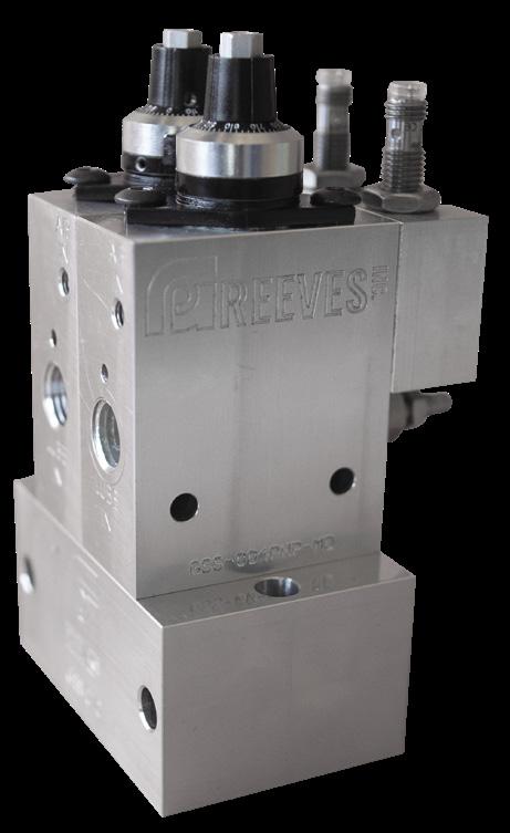
26 | gpreeves.com Dispensers GSS/GSSM DISPENSERS Quick, Ultra-Precise, Positive Displacement Dispensers GSS and GSSM dispensers are identical in all aspects except mounting. GSS dispensers are engineered for individual installation near an application point, whereas GSSM dispensers are designed for installation on manifolds in groups of 2-10 dispensers. Manifold-mounted dispensers have the option to fire together or separately depending on application. Features & Benefits – Uses adjustable volumetric piston displacement to dispense measured shots – Dispenses set amounts regardless of temperature and viscosity changes – For use with low pressure material, with a maximum PSI of 200 – Integral piston stroke sensors are available to confirm operation – Optional Micro Dial features over 450 labeled graduations allowing for easy volume checks and accurate dispensing – Fast: up to 180 operations per minute Sensor CODE DESCRIPTION PNP PNP stroke sensor NPN NPN stroke sensor Base Part Number CODE DESCRIPTION GSS Dispenser designed to be mounted individually GSSM Dispenser designed for manifold mounting Volume CODE DESCRIPTION 001 0.016 cc max. with stroke sensor 002 0.033 cc max. with stroke sensor 004 0.066 cc max. with stroke sensor 011* 0.016 cc max. without stroke sensor 012* 0.033 cc max. without stroke sensor 014* 0.066 cc max. without stroke sensor Adjustment Assembly CODE DESCRIPTION V2 Standard Adjustment Assembly with 50 unlabeled volume graduations MD Micro Dial adjustment assembly which features over 450 labeled graduations Dispenser Part Number Format [Base Part Number]-[Volume][Sensor*]-[Adjustment Assembly] *Volume codes with a 1 as the middle number will not have a sensor Dispenser Part Number Examples GSS-001PNP-MD: Individually mounted grease dispenser with a 0.016 cc maximum shot, a PNP stroke sensor, and a Micro Dial adjustment assembly. GSSM-014-V2: Manifold mounted grease dispenser, with a 0.066 cc maximum shot, no stroke sensor, and a standard adjustment assembly.

© 2022 | 27 Dispensers Manifold Part Numbers STATION NUMBER AIR PORTS 2-10 SA: Each dispenser has a separate air port GSSM dispensers require a manifold to mount. Dispensers can be mounted alone or in groups of 2-10. Manifolds are available with a single or multiple air inlets, allowing for the individual control of each dispenser. Manifold Part Number Builder GSSMB-[Station Number][Air Ports*] *A common air port for simultaneous dispensing is available by omitting the air port section. Example Manifold Part Numbers GSSMB-10SA is a ten-station manifold with separate 1/8” NPT air ports. GSSMB-5 is a five-station manifold with a common port. GSSMB-3SA with three GSSM-001PNP-MD Manifolds for GSSM GSS dispensers have a variety of adaptor options that allow the dispenser to easily connect to various dispense accessories. Outlet Adaptors & Fittings PART NUMBER DESCRIPTION GSS-005 10-32 port GSS-006 1/4-28 port GSS-007 Luer lock fitting with 1/4-28 male GSS-008 1/8” NPT port GSS-010 Dual inlet – single 1/8” NPT outlet GSS-019 10-32 port and tapped tooling GSS-031 M5 x .8 port GSS-037 SAE-2 (female) port GSS-055 Adaptor for SP2000 spray nozzle GSS-072 1/16” NPT port GSS-075 Allows for mounting of FS3014 flow sensor Adaptors for GSS/GSSM GSS-004PNP-MDGSS-004PNP-MDwithGSS-019withGSS-005 GSS-004PNP-MD with GSS-006 and GSS-004PNP-MDsGSS-007withGSS-010


28 | gpreeves.com Dispensers GPMD DISPENSERS Features and Benefits – Base-mountable, air-operated, single-acting, adjustable, metered shot (piston) dispenser – Positive piston displacement dispenser accurately delivers measured shots. – Change shot size quickly and easily using fine-thread adjustment screw with a lock nut. – Uses piston displacement to measure material and will dispense set amounts regardless of temperature. Positive Displacement Piston Dispensers GPMD10000 Features and Benefits – Accurate dispensing of 0.02 cc to 6.20 cc shots of (depending on model selected). – Bases are available with from 1 to 8 stations and also with separate air inlets for independent operation. – Can dispense up to 40 times per minute at the maximum shot size. – Operate at 50 to 120 psi with 3-way NC Air Valve. – Operates with low inlet pressure (up to 200 psi). GPMD10000 Base Part Numbers BASE NUMBERPART VOLUMEADJUSTABLE BOOST RATIO (LESS RETURN SPRING) GPMD10020 0.02 to 0.20 cc 36:1 GPMD10080 0.02 to 0.80 cc 12.25:1 GPMD10125 0.10 to 1.25 cc 11.56:1 GPMD10369 0.13 to 3.69 cc 11.76:1 GPMD10620 0.20 to 6.20 cc 10.24:1 Stroke (Optional)Sensors MDM100X Manifolds NUMBERPART AIR OPTIONSPORT PORTMATERIALSIZE AIR SIZEPORT SIZE*TOTAL MDM1000-X Common 1/4” NPT 1/4” NPT <4 cc MDM1000-XSA Separate 1/4” NPT 1/8” NPT MDM1006-X Common 3/8” NPT 3/8” NPT 4-8 cc MDM1006-XSA Separate 3/8” NPT 1/8” NPT MDM1008-X Common 1/2” NPT 1/2” NPT >8 cc MDM1008-XSA Separate 1/2” NPT 1/8” NPT MDM1000 manifolds have grease inlet ports on both ends. Port size is dependent on part number, see “MDM100X Manifolds” chart. Common air ports are designed for simultaneous operation while separate air will dispense independently. * Size suggestions refer to the total size of the dispensers being installed on the manifold. For example, four GPMD10080 dispensers would be a total of 3.2cc and should use a MDM1000 manifold. Four GPMD10369 dispensers would be 14.76cc and should use a MDM1008 manifold. Blank station manifold kits are available as MDM1000-BS and will work for all three sizes of manifold. Manifolds can also be purchased in a stainless steel version by adding SS to the part number. For example, MDM1008SS-5 is the stainless steel version of MDM1008-5. MDM with SA OptionMDM with Common Air (No SA option)


© 2022 | 29 Options CODE DESCRIPTION CONNECTOR(S) 00 No Options (dispenser will have a magnetic piston) Not Applicable 02 Two M8 PNP Stroke Sensors Two M8 DC Connectors 03 Calibration Scale Not Applicable 12 Two M8 NPN Stroke Sensors Two M8 DC Connectors 16 Inductive Flow Sensor, 24 VDC PNP M12 DC Connector 17 Inductive Flow Sensor, 24 VDC NPN M12 DC Connector 18 Analog Flow Sensor (0-10V) M12 DC Connector 22 Premium Seals for Use with Abrasive Material Not Applicable 26 Flow Sensor, Digital 24 VDC PNP/NPN, Analog 0-10V or 4-20mA (IFM Sensor) M12 DC Connector 27* Analog Stroke Sensor (0-10V Analog) M8 4 pin DC Connector 28 Viton Seals (Rod seals, face seals, and check seals) Not Applicable Notes: Each M8 stroke sensor requires a #0983 cord. Single stroke sensors will be factory set to recognize “dispense complete" message. Each flow sensor or M12 stroke sensor requires a #1850 cord. * Only for use with GPMD3000 dispensers. GPMD3000 Series Dispensers PART NUMBER VOLUMEADJUSTABLE INLET RANGEPRESSURE GPMD3000-.60 0.05 to 0.60 cc 600 – 3,000 PSI GPMD3000-2 0.15 to 2.00 cc 400 – 3,000 PSI GPMD3000-5 0.25 to 5.00 cc GPMD3000-9 0.35 to 9.00 cc GPMD3000-20 5.00 to 20 cc GPMD3000-40 5.00 to 40 cc GPMD3000-100 20 to 100 cc GPMD3000-210 20 to 210 cc GPMD3000 Features and Benefits – Adjustment requires wrenches to prevent accidental volume adjustment – Air operated check valves facilitate quick fill and quick dispense while preventing leaks – Threaded adjustment rod is a visual indicator – Operates with high inlet pressure up to 3,000 PSI Shown GPMD3000-9-02as ControlGPMD3000Package solenoidControllerGPMD30CP:withvalves Part Number Format: [Base Part Number]-[Options] Note: Part number must include at least one Option ID to be complete. Options should be listed in numerical order and delimited by dashes. For a dispenser with no options, add -00 to the end of the part number. Options are listed on the next page. Example Part GPMD10080-02-03:Numbers:GPMD10080 dispenser with maximum shot volume of 0.80 cc, two PNP stroke sensors and calibration scale. GPMD3000-2-00: GPMD3000 dispenser with volume range of 0.15 - 2.00 cc, inlet pressure range of 400 - 3,000 PSI, and no options. Dispensers


30 | gpreeves.com AA DISPENSERS Solenoid Valve Stack (Optional) Positive Displacement Pneumatic & Servo Dispensers Features and Benefits – Patented air removal process ensures only airless material is dispensed into your manufacturing process – Provide accurate volume & dispense rate control through positive displacement – Flow-through design reduces the pack out of material – Provides PLC volume confirmation Our AAs also measure volume through the use of positive displacement and constant sensor positioning. This provides an extra level of confirmation that none of our other dispensers offer. The previously dispensed volumes can be reported to a separately purchased AA-CT controller which is recommended for all AA dispensers. Manufactured under US patent number 6,053,285. Shown AA1-9-ST-2-NPNas Pneumatic Base Part Number CODE VOLUME RANGE AA1-4 0.40 - 4.00 cc AA1-9 0.45 - 9.00 cc AA1-13.5 1.35 - 13.5 cc AA1-27 2.70 - 27 cc AA1-50 5.00 - 50 cc AA1-120 12 - 120 cc AA1-148 3.00 - 148 cc AA1-230 23 - 230 cc AA1-480 48 - 480 cc AA1-700 70 - 700 cc Servo v. Pneumatic Pneumatic AA1 Dispensers Pneumatic AA dispensers allow for PLC volume and rate control without the added cost of a servo. – Ideal for applications where recipe control is more important than repeatable volume. – Aren’t as precise when using extremely thick materials. – Utilizes PID loop controls to actuate and dispense. – Generally have a lower cost than servo models. Servo AA8 Dispensers Servo driven AA dispensers provide accurate volume and dispense rate control, coupled with a patented air removal process to be used for critical applications. – Hold tighter tolerances guaranteeing an accurate dispense every time. – Automatically adjusts piston movement to maintain required dispense volume and rate. – Simpler to operate and tune than pneumatic counterpart. – Provides more control within a single size. Dispensers

*
AA8-2C-ST-1-EN2: Servo AA dispenser has a volume range of 0.05 - 2.00 cc. Dispenser comes on a standard mounting plate with one non-spray output port. Dispenser includes a valve stack with NPN Ethernet IP. AA8-12C-ST-1R3-EN1: Servo AA dispenser has a volume range of 0.30 - 12.00 cc. Dispenser comes on a standard mounting plate with one output port with 3 station selectors downstream. Dispenser includes a valve stack with PNP Ethernet IP. Only for use with pneumatic AA1 dispensers. all options work together. Contact our sales team to build your AA.
Not
© 2022 | 31 Dispensers Mounting CODE DESCRIPTION ST Standard mounting plate NP* Narrow mounting plate FL Floor mounted aluminum extrusion stand Port CODE DESCRIPTION 1 1 output port non-spray 2 2 output ports non-spray 1SP 1 output port with spray 2SP 2 output ports with spray 1RX 1 output port for connection to a zone valve with X dispense zones downstream Part Number Format [Base Part Number]-[Mounting]-[Port]-[Options] Options CODE DESCRIPTION EN1 Valve Manifold with EthernetIP, PNP EN2 Valve Manifold with EthernetIP, NPN PNP* Discrete Valve Manifold, PNP NPN* Discrete Valve Manifold, NPN Servo Base Part Number CODE VOLUME RANGE AA8-1C 0.02 - 1.00 cc AA8-2C 0.05 - 2.00 cc AA8-4C 0.10 - 4.00 cc AA8-9C 0.20 - 9.00 cc AA8-12C 0.30 - 12.00 cc AA8-25HPC 1.00 - 25.00 cc AA8-60C 1.20 - 60.00 cc Example Part AA1-120-ST-1-PNP:Numbers Pneumatic grease dispenser with PLC volume and rate control. This dispenser has a volume range of 12 - 120 cc, a standard mounting plate and one non-spray output port. Dispenser includes a discrete PNP valve stack. AA1-13.5-NP-1R3SP-EN1: Pneumatic grease dispenser with PLC volume and rate control. This dispenser has a volume range of 1.35 - 13.5 cc, a narrow mounting plate and one spray output port with 3 station selectors downstream. Dispenser includes a valve stack with PNP Ethernet IP.
Ethernet/IP Solenoid Valve Stack (Optional) Shown as AA8-25HPC-ST-1-EN1

32 | gpreeves.com Dispensers ROTOMETER The RotoMeter is a stepper-driven gear pump designed to be used for both continuous flow and measured dispensed applications. The dispenser is able to match the dispense rate with a variety of speeds and even change dispense rate during dispense to work seamlessly with robots. With a variety of motor options, these dispensers can be customized for any application. Dispensers are designed for a maximum of 600 PSI inlet and 700 PSI outlet pressure. Note: All RotoMeters require a dispense valve to be installed near the material outlet to prevent unwanted material oozing. Features & Benefits – Compact: Continuous flow allows for larger dispense volumes without a larger dispenser. – Versatile: This pump is perfect for both continuous flow and measured dispense applications. – Easy Adjustment: Separately purchased controller makes volume and rate adjustments simple. – Adjustable Snuff-back: Minimize/reduce drooling. Part Number Builder RM-[Size]-[Motor] Motor CODE DESCRIPTION MT1 REEVES 24 VDC stepper with encoder Size CODE DESCRIPTION 0.15 Dispenses 0.15 cc per revolution, 1/4” NPT port, flow rate of 0.15 to .30 cc per second in rate mode 1.8 Dispenses 1.8 cc per revolution, 1/4” NPT port, flow rate of 1.8 to 3.6 cc per second in rate mode 6 Dispenses 6 cc per revolution, 1/2” NPT port, flow rate of 6 to 12 cc per second in rate mode Part Number Examples RM-0.15-MT1: 0.15 cc RotoMeter with 1/4” NPT ports and a REEVES 24VDC stepper with encoder. RM-6-MT1: 6 cc RotoMeter with 1/2” NPT ports and a REEVES 24VDC stepper with encoder. InletMaterial Material Outlet (Not Shown) Continuous Flow Gear Pump

© 2022 | 33 Dispensers PROGRESSIVE SCREW ROTOMETER Continuous Flow Progressive Cavity Pump This stepper-driven progressive screw pump is an ideal solution for all continuous flow, and measured dispensed applications. With a smart core, it’s able to match a variety of speeds and even change dispense rate during dispense to work seamlessly with robots. These dispensers have a variety of motor and adapter options in order to customize them for your specific application. Dispensers are designed for a maximum of 90 PSI inlet and 150 PSI outlet pressure. Features & Benefits – Accuracy: Screw pump ensures more precision than other continuous flow options – Compact: Continuous flow design allows for larger dispense amounts without a larger dispenser. – Versatile: This pump is perfect for both continuous flow, and measured dispense applications. – Compatibility: Pump design is ideal for materials that separate or are shear-sensitive. – Easy Adjustment: Separately purchased controller makes volume and rate adjustments simple. – Adjustable Snuff-back: Minimize/reduce drooling. Part Number Builder: RMP-[Size]-[Motor]-[Options] Motor CODE DESCRIPTION MT1 REEVES 24 VDC stepper with encoder Size CODE DESCRIPTION 1 Dispenses 1 cc per revolution, 1/4 BSP port, 2.5 cc to 35 cc per minute output in rate mode 2 Dispenses 2 cc per revolution, 1/4 BSP port, 5 cc to 70 cc per minute output in rate mode Part Number Examples: RMP-2-MT1: 2 cc Progressive Screw RotoMeter with a REEVES 24VDC stepper with encoder. RMP-1-MT1-6F: 1 cc Progressive Screw RotoMeter with a REEVES 24VDC stepper with encoder and a female 3/8” NPT adapter on outlet. Material Inlet Material Outlet Options CODE DESCRIPTION 2F Includes female 1/8" NPT adapter on outlet. 2M Includes male 1/8" NPT adapter on outlet. 4F Includes female 1/4" NPT adapter on outlet. 4M Includes male 1/4" NPT adapter on outlet. LR Includes luer lock adapter on outlet.

34 | gpreeves.com ArmofEndEndPoints LOW FLOW DISPENSE VALVES Features & Benefits – Reduces drooling by shutting off flow near the point of dispense – Options for a maximum inlet pressure of 3,000 PSI – Can be used with “timed dispense” systems – Available in multiple sizes and gun options – Cleanable and repairable Dispense valves provide crisp shutoff when mounted at the point of dispense, can ensure material holds a steady pressure and are available in a wide range of configurations. DV1007 valves are ideal for use with precision mount tooling. DV1006 valves are available for similar applications requiring sprayed material. Additional information about DV1006 can be found on the spray nozzle page. Standard Dispense Valves BASE NUMBERPART PORTSINLETMATERIAL RATINGPRESSUREMATERIAL DESCRIPTION VALVEREPLACEMENT DV1003 1/8” NPT 1,500 PSI Standard GPR7379 DV1003I 1/16” NPT Inline (Slim manifold)DV1003I2 1/8” NPT DV1003TM Includes integrated flow control for timed dispense DV2003 1/4” NPT 3,000 PSI Standard GPR8596 DV2003TM Includes integrated flow control for timed dispense Outlet Options Available for Standard Dispense Valves* CODE DESCRIPTION 0 No outlet adaptor (Male 3/8-24) 2F 1/8” NPTF adaptor 4F 1/4” NPTF adaptor 2M 1/8” NPT adaptor 4M 1/4” NPT adaptor SP Spray air nozzle included LR Luer lock outlet port ZK Includes female zerk fitting CAUTION: Due to viscosity variations with temperature, “timed dispense” is often not accurate enough to meet many quality control specifications. Shown as DV1003-2F Shown as DV1003-0 * One option MUST be selected. Options are added to the end of the base part numbers as a suffix. For example, DV1003-SP would be a DV1003 with spray air nozzle and DV2003-Z would be a DV2003 with female Zerk fitting. DV1007 PART NUMBER MATERIAL PORTS MATERIAL PRESSURE RATING DISPENSE VALVE TYPE REPLACEMENT VALVES DV1007 1/8” 1,500 PSI Inline GPR7379


© 2022 | 35 HIGH FLOW DISPENSE VALVES Shown as DV3239A-EPS with EPS1007 Part Number Material Ports Material Inlet Pressure Rating Replacement Valves Options Available DV2973A 1/4” 3,000 PSI ACE8-3000-600-007 –EPS: Includes SAE #4 port on the side for EPS sensor (purchased separately) DV3239A 1/4” ACE8-3000-3000-007 DV5313 3/8” ACE10-3000-600-040 Options are added to the end of the base part numbers as a suffix. For example, DV3239A-EPS would be a DV3239A with an SAE #4 port for EPS1001 pressure sensormounting. – Maximum inlet pressure of 3000 PSI – Can be used with “timed dispense” systems – Available in multiple sizes and pressure ratings – Cleanable and repairable Shown as DV5313 Dispenser Dispense Valve Nozzle/Tooling Example Usage Layout PointsEnd


36 | gpreeves.com HANDHELD DISPENSE GUNS Handheld dispense guns have an ergonomic fit with an electronic trigger. Handles are lightweight yet durable to last without causing fatigue. Handhelds are equipped with a GPR7379 dispense valve or an ACE8 cartridge valve. Electronic trigger is designed to be a PLC input only. Vertical Style Shown as DG-V-DV1-4M Horizontal Style Shown as DG-H-DV1-LR Handle Styles CODE DESCRIPTION P Pistol Grip V Vertical Grip H Horizontal Grip Nozzle Options CODE DESCRIPTION 0 No Fitting LR Luer Lock Fitting 2M 1/8” NPT Male Threads 2F 1/8” NPT Female Threads 4M 1/4" NPT Male Threads 4F 1/4” NPT Female Threads BR Brush SL Slotted for Nozzle Sensor Cable SP Fine Cone Spray ZK Female Zerk Fitting NT No Trigger Dispenser CODE DESCRIPTION DV1 Dispense Valve (GPR7379) DV3 Dispense Valve (ACE8) – Pistol Grip Only Part Number Format for Gun: DG-[Handle]-[Dispenser]-[Nozzle] Example Gun Part Numbers: DG-H-DV1-LR – Dispense Gun with the horizontal handle with a GPR7379 dispense valve and a luer lock fitting. DG-P-DV3-0 – Dispense Gun with the pistol grip handle with an ACE8 dispense valve and no nozzle fitting.PointsEnd


© 2022 | 37 PointsEnd ZONE VALVES Zone valves allow for material from a single input to be dispensed out of multiple outlets. A zone valve is used between a dispenser and multiple nozzles so that only one source is required for delivery to numerous stations. They are designed for inlet pressure up to 3,000 PSI (depending on model) and require solenoid valves to operate. Features & Benefits – Options available for up to 12 outputs. – Zone valves can dispense to each outlet individually, though only one outlet can be triggered at a time. – Designed for inlet pressure up to 3,000 PSI (depending on model). ZV1000 Series Shown as ZV1000-3-4A A B B C C Material inlets shown as A, material outlets shown as B and air inlets shown as C. ZV1003 Series Shown as ZV1003-6-2 ZV1000 Series PART NUMBER MAXIMUM INLET PRESSURE NUMBER OF OUTLET PORTS (X) INLET / OUTLET PORT SIZE (Y) PARTVALVENUMBERCODE SIZE ZV1000-X-Y 3,000 PSI 2 - 4 2 1/8” NPT ACE8-3000-600-007 4 1/4” NPT 6 3/8” NPT 8 1/2” NPT ZV1003 Series PART NUMBER MAXIMUM INLET PRESSURE NUMBER OF OUTLET PORTS (X) PORTINLET SIZE OUTLET PORT SIZE (Y) VALVE NUMBERPARTCODE SIZE ZV1003-X-Y 1,500 PSI 2 - 12 1/8” NPT 2 1/8” tube compression fitting GPR73792F 1/8” NPT female 4F 1/4” NPT female


38 | gpreeves.com EXTRUSION NOZZLES Luer Lock Adaptors PART NUMBER MATERIAL PORT LLA-10-32 10-32 Male LLA-1/4-28 1/4-28 Male LLA-2 1/8” NPT Male LLA-4 1/4” NPT Male Luer Lock Nozzles PART NUMBER DIAMETEROUTER DIAMETERINNER X = (INCHES)LENGTH LLN-.050-X .050 .033 Max of 6” LLN-.072-X .072 .054 LLN-.109-X .109 .085 LLN-.134-X .134 .106 LLN-.165-X .165 .135 LLN-.219-X .219 .189 Dispense Valve Nozzles PART NUMBER ORIFICE SIZE WALL THICKNESS IN INCHES X = LENGTH (INCHES) FOR USE WITH DVN1-.063-X .063 .16 1" to 6" in increments1/4” DV1003-0 DVN1-.094-X .094 .14 DV1003-0 DVN2-.063-X .063 .12 DV2003-0 NOTE: Luer lock nozzles are to be used with separately purchased luer lock adaptors. DVN NozzleLuer Lock NozzleLuer Lock Adapters PointsEnd


© 2022 | 39 PointsEnd SPRAY NOZZLES SpraySP1002Patterns&SP1004 Series Nozzles PART NUMBER MATERIAL PORTS AIR INLET PORT X = PATTERNSPRAY X=LENGTH IN INCHES MOUNTING STYLE SP1002-XX-X 1/8” tube compression 1/8” tube barb SC, FC 2”-24” Bulkhead fitting SP1004-XX-X 1/4” tube compression 1/8” tube barb SC (Solid Cone): – Ideal for spraying a wide variety of surfaces – Works with varying viscosities FC (Fine Cone): – Great for spraying thick grease – Perfect for applications where uniform coverage is critical DV1006 Series Nozzles PART NUMBER MATERIAL PORTS PRESSUREMATERIAL RATING DISPENSE VALVE TYPE REPLACEMENT VALVES DV1006 1/8” 1,500 PSI Inline GPR7379 DV1006 Options CODE DESCRIPTION SPFC-X Fine cone spray nozzle where X is the length in inches (1/2” increments from 1-3”). SP90FC-X Fine cone spray nozzle where X is the length in inches (1/2” increments from 1-3”) and the material is sprayed at a 90º angle. Shown as SP1002-SC-3 DV1006 Part Number Builder DV1006-[Option Code] Part Number Examples DV1006-SPFC-3: 3” fine cone spray nozzle with 1/8” material ports. DV1006-SP90FC-1.5: 1.5” fine cone spray nozzle with 1/8” material ports and a 90º spray. Shown as DV1006-SP90FC-1.5


40 | gpreeves.com G-FORCE TM NOZZLES Our patented G-ForceTM Nozzles are bore dispensing nozzles that dispense material in a radial pattern on the inner diameter of a part. Electric models require GFCM controller. G-Force™ nozzles are often paired with AA8 Servo Dispensers and servo motion setups for continuous, even coating dispenses. The liquid option of the nozzle includes a check valve near the tip to prevent dripping. Nozzles are not designed for use with most RTV or epoxy. See the Material Type table on the next page for more information. Custom nozzles and air turbine models are available for special applications. Radial ID Applicator Shown as GFNE-TL-DV1-02 Inline Mandrel Style Standard Electric Powered Style Shown as GFNE-4G-DV1-01 Disk for Grease Disk for Oil Close up of Nozzle and Dispensing Disks GFCM Control Module Result Photo of Film Dispense on 3” Diameter Spline Part Result Photo of Ring Dispense on 1.5” Clear Cylinder PointsEnd


© 2022 | 41 Part Number Builder GFNE-[Nozzle Length][Material Type]-[Dispenser]-[Disk] Part Number GFNE-6L-GSS-01:Examples Electric 6” nozzle, liquid, mounting for GSSM dispenser, and a standard wide band. GFNE-14G-DV1-01: Electred powered, 14” nozzle, grease, DV1003 dispense valve, and a standard wide band. Nozzle Length (front of turbine to front edge of disk) CODE DESCRIPTION MIN. DIAMETER MAX. DEPTH 2 2” Nozzle 1.25” round/rectangle 2” 4 4” Nozzle 1.25” round/rectangle 4” 6 6” Nozzle 1.25” round/rectangle 6” T Mandrel Style Nozzle* 2.25” round or 1.5” x 2” rectangle 48” GFCM Controllers (Complete System PLC Controllers are Available) CODE MOUNTINGENCLOSURE/ MONITORINGROTATION REQUIREMENTPOWER CONNECTION GFCM Control Module Only No 24DC/4A Wired Connection to Customer PLC GFCM-B NEMA 12 Enclosure No 24DC/4A 4 Pin Euro M12 GFCM-M Back Panel Yes 24DC/4A Wired Connection to Customer PLC GFCM-MB NEMA 12 Enclosure Yes 24DC/4A 4 Pin Euro M12 GFCM-B-120 NEMA 12 Enclosure No 120VAC, 24V Enable 4 Pin Euro M12 to Enable, Wired Connection to 120VAC GFCM-MB-120 NEMA 12 Enclosure Yes 120VAC, 24V Enable 4 Pin Euro M12 to Enable, Wired Connection to 120VAC Disk CODE DESCRIPTION 01 Standard Wide Band Disk 02 Standard Liquid Disk *** 03 Narrow Band Disk Material Type CODE DESCRIPTION G Grease (Viscosity over 5,000 cP) L Liquid (Viscosity under 10,000 cP) Dispenser CODE INCLUDES APPLICATION DV1 DV1003 Dispense Valve Film / Ring DV2 DV2003 Dispense Valve Film / Ring GSS Mounting for GSSM Dispenser** Ring GSSD Mounting for two GSSM Dispensers** Film / Ring * Only available with DV1 dispenser type. ** GSSM dispensers are purchased separately. *** 02 Disk can only be used with L material type. Listed maximum and minimum values are for the entire series, nozzle type and length determines actual values. PointsEnd


42 | gpreeves.com CUSTOM NOZZLES,NESTS,&TOOLING GP Reeves specializes in creating the ideal dispensing aparatus for any application. From custom spray nozzles to multi-part nests, we've done it all. PointsEnd


© 2022 | 43 PointsEnd


CONFIRMATION
Accessories
We offer several different confirmation devices. These devices are suggested to be used as redundant verification only. Choosing one is based solely on what your specific project needs are. There are three main categories of confirmation devices: flow, pressure, and volume. Flow confirmation devices are the most common, and usually the most basic. Pressure confirmation devices are mid-level, and volume confirmation devices are generally the most advanced. It is important to remember that flow, pressure, and volume, though related, are all different.
All flow confirmation devices are meant to detect flow failure for critical dispense points. When would you need it?
System Example DispenserPump FS/EPS Tooling
DEVICE BREAKDOWN
44 | gpreeves.com
Examples – Verification of material supply from pump/source – Confirmation of correct regulator settings
We offer three different types of flow confirmation devices based on function and feedback signal. Each type has it’s advantages, and all are useful in different scenarios. Some of our devices just confirm flow – a simple yes or no. Others provide variable feedback that can be used to adjust the device.
These devices are designed to be mounted between supply (pump) and the dispenser with the purpose of confirming proper feed pressure.
System Example Pump Regulator EPS Dispenser Tooling Flow Confirmation What is it?
Flow confirmation devices come in handy in any situation where you want to double check that material is flowing. Examples – Cloggled nozzle in part nest – Verification of air pressure – Detection of small air bubbles
We have pressure confirmation devices that provide digital, analog, discrete, PNP, or NPN feedback with up to 3,500 PSI. These can be set to a specific range, and it will trigger a signal to the system/controller if outside set range. When would you need it? These devices are used to confirm correct feed pressure of a system.
In general, flow confirmation devices do just that, confirm if there is flow through the device. These devices mount between the dispenser and tooling.
Feed Pressure Confirmation What is it?
Examples –
© 2022 | 45 Dispenser Dispenser Dispensers AA Dispenser Nozzle Pressure Confirmation
What is it?
We
Examples – Cloggled
Volume confirmation devices can measure the volume of material flowing through a device. have two specialized devices that confirms volume, VMFG and UFS. These devices can be placed anywhere in a system, though they are usually used between the dispenser and the tooling. In addition to these devices, our AA dispensers are positive displacement dispenser with air removal and constant sensor positioning, which allows them to confirm volume as well. When would you need it?
Volume confirmation is important if you want to confirm how much material flowed through a specific device. They should be used as confirmation devices opposed to control devices in a system. Redundant volume verification flow applications Measure flow before a dispenser
– Continuous
We
line
–
block System Examples Pump PumpPumpPump Regulator EPS UFS/VMFG Regulator Tooling Tooling ToolingUFS/VMFG Tooling Accessories
What is it?
nest parts –
These devices are designed to be mounted between the dispenser and the tooling with the purpose of confirming proper pressure. have pressure confirmation devices that provide digital, analog, discrete, PNP, or NPN feedback with up to 3,500 PSI. These can be set to a specific range, and it will trigger a signal to the system/controller if outside set range. When would you need it? These devices are used to confirm proper pressure going to the nozzle of the system. nozzle of over-pressurization of Disconnected (low
pressure) System Example Volume Confirmation
in part nest – Detection
Disadvantages –
–
Flow Confirmation
Material pressure reading correlates to 0-10V output signal. Mounting Can be mounted anywhere in a system on an inline manifold to measure feed or nozzle pressure. Mounts to SAE #4 port. Provides actual pressure readings Requires analog input Flow Confirmation
PLC analog input monitors pressure spikes to confirm flow. ∆P can be used to allow pressure limits to selfadjust as the viscosity changes. Mounting Should be mounted at the outlet of a dispenser for flow confirmation. Detects small air bubbles Works with low dispense velocity Works with contaminated material Requires analog input Requires PLC programming
Disadvantages –
PRESSURE SENSORS Accessories
–
IO-Link MountingCompatible Can be mounted anywhere in a system on an inline manifold to measure feed or nozzle pressure. 1007 sensor has a female G1/4 port which comes with a male SAE #4 adaptor installed. 1005A sensor has a female SAE #4 port with a male SAE #4 adaptor installed. Versatile usability Simplistic functionality yields minimal nuisance faults Configurable output signal: PNP/NPN, NO/NC Reads in increments of 5psi when in discrete mode
Advantages –
Advantages –
Disadvantages –
EPS1001
Material pressure reading correlates to 0-10V or 4-20mA output signal. Uses dual setpoints to confirm pressure within set range. Readings are in 5 PSI increments.
–
–
& 1002 Pressure Confirmation How it Analog:Works
–
46 | gpreeves.com EPS1005A & 1007 Pressure Confirmation How it Analog:Works
–
Discrete:
Advantages –
PLC analog input monitor pressure spikes to confirm flow. ∆P can be used to allow pressure limits to selfadjust as the viscosity changes. Discrete mode not recommended for flow confirmation. Mounting Should be mounted at the outlet of a dispenser for flow confirmation. Disadvantages Requires analog input – Requires PLC programming


© 2022 | 47 Part Number Examples EPS1001 is an SAE #4 0-10V analog sensor with a max pressure of 870 PSI and no manifold. EPS1007-6 is an inline mounted sensor with a pressure range of 0-3,500 PSI and a manifold with 3/8” NPT port sizes. EPS1010-4A is a flush face 4-20mA analog sensor with a max pressure of 3,625 PSI and an adaptor with SAE #4 fitting. Mounting CODE PORT SIZE no manifold or adaptor -2 1/8" NPT manifold -4 1/4" NPT manifold -6 3/8" NPT manifold -8 1/2" NPT manifold -4A SAE #4 male adapter fitting -6A SAE #6 male adapter fitting Part Number Format [Base Part Number][Mounting] NumberPart Description RangePressure EPS1001 Male SAE #4 housing, 0-10V Analog 0 – 870 PSI EPS1002 0 – 3,000 PSI EPS1005A Male SAE #4 housing, configurable for digital, analog, discrete, PNP or NPN 0 – 1,450 PSI EPS1007 0 – 3,500 PSI EPS1009 Flush face mounted (requires male adaptor fitting), 4-20 MA 0 – 870 PSI EPS1010 0 – 3,625 PSI EPS1011 0 – 5,800 PSI EPS1009, 1010, & 1011 Pressure Confirmation How it Analog:WorksMaterial pressure reading correlates to 4-20mA output signal. Mounting Can be mounted anywhere in a system on an inline manifold to measure feed or nozzle pressure. Requires specialized adapter fitting for G1/4 externally threaded connection with extended sensing face. Advantages – Provides actual pressure readings Disadvantages – Requires analog input – Requires specialized adapter Flow Confirmation Uses analog input to monitor pressure spike to confirm flow. PLC is used to monitor and adjust pressure spikes. ∆P can be used to allow pressure limits to selfadjust as the viscosity changes. Mounting Should be mounted at the outlet of a dispenser for flow confirmation. Accessories

One switch output for every 3.05 cc. 1/2” NPT 1,450 PSI Shown as AA1-9-ST-1-PNP
One switch output for every 0.10 cc. Includes controller. 3/8” NPT
Volume confirmation can also be achieved with use of an AA dispenser. AA dispensers acheive volume confirmation through positive displacement dispensing coupled with our patented air removal system and constant position sensing. We offer pneumatic and electronic (servo) versions of these dispensers in a variety of sizes. See AA pages for more information.
One switch output for every 0.10 cc. 3/8” NPT 2,900 PSI
One switch output for every 0.025 cc. Includes controller. 3/8” NPT
VMFG-3
VMFG-25-C
Shown as VMFG-1 Accessories
48 | gpreeves.com VOLUME CONFIRMATION - MECHANICAL Confirms volume of flow for critical dispense points. The VMFG devices are designed to mount between a dispenser and the tooling. They are used to confirm the proper volume was dispensed through the use of gears. VMFG Flow Meters How They Work: Material flows through precise gears to rotate them. The output is sent every time the gear is rotated. Each rotation is equivelant to a certain volume, depending on the model. Advantages: – Flow through device allows for continuous flow. – Small footprint Disadvantages: – Does not work well with contamination – Does not work well finding small air bubbles – Less accurate with thin material – Has to be calibrated – Requires high speed PLC input Part Number Description Port Sizes Max Pressure VMFG-1
VMFG-25
VMFG-1-C
One switch output for every 0.025 cc. 3/8” NPT


© 2022 | 49 VOLUME CONFIRMATION - ULTRASONIC UFS Part Numbers PART NUMBER TUBE SIZE RANGE ACCURACY UFS1000-2 1/8” Tubing 0.10 - 900 cc +/-.005 cc UFS1000-4 1/4” Tubing 0.10 - 900 cc +/-.005 cc UFS1000-6 3/8” Tubing 20 - 900,000 cc +/-1.00 cc UFS1000-8 1/2” Tubing 20 - 900,000 cc +/- 1.00 cc These devices are designed to be clamped around any nylon tubing in your system. Ultrasonic waves monitor material flow and the volume dispensed is shown on the controller. How They Work Two signals facing opposite directions are being simultaneously monitored. This allows readings to remain consistent regardless of external factors such as clogging or temperature changes. Advantages – Does a great job finding small air bubbles – Does not disturb material flow – NPN, PNP, and IO link capable Disadvantages – Requires calibration – Should not be used with material that has a separation percentage over 2% – Must be used with nylon tubing Shot Size vs Accuracy 0.10.20.30.40.50.60.70.80.91(cc)SizeShot 88 90 92 94 96 98 100 Accuracy (%) Accessories


FS3009-2 Inline mounted, 10-30
confirmation Part Number Description PressureMaximum Port Size Applications FS3001 Manifold mounted, 20-250
Detect
FS3009-4
FS3002 Manifold mounted, 10-30
Accessories
50 | gpreeves.com
–
Disadvantages –
–
Advantages –
wire)
wire) FS3002NPN Manifold mounted, 10-30
FS3009NPN-2
FS3009NPN-4
–
FS3014
How They Work A small plunger (monitored by a sensor) is moved by the material when material flows through the device. If the sensor light is off, it means material is flowing, if the light it on it means there isn’t any material flowing. The plunger is not moved by air bubbles when they pass through the device. Simple to adjust and program Does a great job finding small air bubbles Inexpensive Available as a GSS and GPMD option Does not work well with material that has contamination Must be mounted close to dispenser (or injector) to assure dispense velocity Inductive flow sensors do not have volume V AC/DC (two 3,000 PSI FSM 1/4”availableManifoldsin1/8”,and3/8”ports For use with high pressure and high flow systems. VDC PNP (DC three VDC NPN (DC three wire) VDC PNP (DC three wire) 1,000 PSI 1/8” For use with low pressure and low flow systems. 1/4” Inline mounted, 10-30 VDC NPN (DC three wire) 1/8” 1/4” Face mounted for use with GSS/GSSM dispensers, 10-30 VDC PNP (DC three wire) 600 PSI 1/8” Pair with GSS-075 adaptor for low flow, low pressure systems. as FS3009-2 flow failure for critical dispense points. These devices are designed to mount between a dispenser and the end of arm tooling. They are used to detect flow in the line. Our inductive flow devices use an inductive proximity switch to send a signal to the controller to confirm flow. These devices do not measure pressure or volume – just the existence of flow. An inductive flow sensor is ideal where volume and pressure are not important, but confirmation of flow is important.
–
–
FLOW CONFIRMATION - INDUCTIVE Shown

© 2022 | 51 DISPENSE CONTROL HUB Features & Benefits – Compact: These units are available for tabletop and standard wall mounting. – Versatile: Control hubs are available with a variety of HMI sizes, inputs, signals, and enclosure styles. – Easy Adjustment: Controller makes volume and rate adjustments simple. Part Number Builder DCH[Size]-[Dispenser]-[Amount]-[Enclosure]-[Communication] Dispenser CODE DESCRIPTION RM RotoMeter Series GS GSS Series G1 GPMD10000 Series G3 GPMD3000 Series Enclosure CODE DESCRIPTION C Console for Tabletop Mounting E Enclosure for Back Mounting Size CODE DESCRIPTION 4 4” HMI 7 7” HMI Dispenser Amount CODE DESCRIPTION 1 Single Dispenser Communication CODE DESCRIPTION P PNP N NPN Part Number Examples DCH7-G1-1-C-P: A 7” PNP HMI programmed to work with one GPMD10000 series dispenser in a tabletop console enclosure. DCH4-RD-1-E-N: A 4” NPN HMI programmed to work with one RotoMeter series dispenser in a wall-mount enclosure. For use with GSS, GPMD, RotoMeters, and more! The Dispense Control Hub is simplifying controls for our standard material dispensers! These units support most of our dispenser product families, including GSS’, GPMDs, and RotoMeters. One DCH can control a single dispenser with stroke and part in place sensors. DCH cannot control flow sensors. Custom options are available to support more advanced systems. Controllers

52 | gpreeves.com STANDARD AA CONTROLLERS – Designed to control one or two pneumatic AA dispensers – Allows for up to 10 user defined part recipes – Feature 3 modes; Volume/Time, Pressure Control and Rate Control – Optional EtherNet/IP Slave communication Controller shown as AA-CT-H4-PNP A controller part number consists of a combination of codes for the number of dispensers, display size and wiring type. The part number builder can be found below with format and various codes. AA-XXX-HX-XXX-XXX Number of Dispensers CT – One Dispenser CT2 – Two Dispensers PLC / HMI Combo 4 – 4” HMI 7 – 7” HMI Wiring Type PNP – Sourcing Outputs* NPN – Sinking Outputs* EN – Ethernet Slave Only *Also includes Ethernet Slave Communication OmitVoltagefor 24 VDC Power 120 – 120 VAC Power 240 – 240 VAC Power Controllers

© 2022 | 53 CUSTOMIZED CONTROL PACKAGES Size CODE DESCRIPTION CT One dispenser CT-2K One 2K dispenser CT2 Two dispensers CT2-2K Two 2K dispensers CT3 Three dispensers CT3-2K Three 2K dispensers CT4 Four dispensers CT4-2K Four 2K dispensers CT5 Five dispensers CT5-2K Five 2K dispensers CT6 Six dispensers CT6-2K Six 2K dispensers CT7 Seven dispensers CT8 Eight dispensers PLC CODE DESCRIPTION ABLX Allen Bradley CompactLogix SM200SP Siemens Simatic ET 200SP KEY Keyence KV-8000 Dispenser CODE DESCRIPTION AA AA Dispenser RM RotoMeter Dispenser HMI CODE DESCRIPTION GPR6 REEVES 6” KE7 Keyence 7" GPR8 REEVES 8” GPR10W REEVES 10” PV700 Allen Bradley Panel View 7” PV1000 Allen Bradley Panel View 10” Options CODE DESCRIPTION Euro Follows European Power Standards (230V) SV* Servo Controller Included RS Networking for Remote Support Device Shown as AA-CT1-ABLXSV-GPR8Shown as AA-CT-SM200SP-CM7 Our customized control packages start with industry standard components selected by customers to match the plant requirements. The programs are customized to control as many dispensers as required along with the pump(s) to feed them. Custom control of other components is also an option. Part Number Format [Dispenser]-[Size]-[PLC]-[HMI]-[Options] Part Number AA-CT4-ABLXSV-GPR10W:Examples A controller powering four servo AAs, with Allen-Bradley CompactLogixTM PLC, and Reeves 10” HMI. RM-CT-2K-KEYSV-KE7: A controller powering a 2K RotoMeter, with a Keyence KV-8000 PLC, and a 7” Keyence HMI. * SV option code gets added to the PLC code, ex: ABLXSV Note: These options are the PLC/HMI options that we have worked with most commonly for our customers. If you have a different requirement, please reach out to the sales staff to find a solution. Controllers


54 | gpreeves.com Reference ACE CARTRIDGE VALVES ACE8 & ACE10 – 2-way, normally closed, air-actuated poppet valve, for use in SAE 8-2 and SAE 10-2 cavities (depending on model) – The actuator is isolated from the media section (cartridge) by a vent to atmosphere – Air pilot to open passage between port 1 and port 2 – Media section (cartridge) capable of functioning with 3,000 PSI material – Poppet and seat are lapped tungsten carbide for long life with abrasive material – 1/8” NPT air pilot port has a pressure range of 50 psi to 130 psi ACED – 2-way, closed bias, air-actuated ball and seat valve – Manifold or SAE port mounting available – Seal chamber is packed with grease for vapor barrier – Air actuated open and close with spring bias closed – Capable of functioning with 4,500 PSI material – Poppet and seat are lapped hardened steel for long life with abrasive material – 1/8” NPT air pilot ports have a pressure range of 60 PSI to 130 PSI These patented cartridge valves are used on many of our products including AA, GUS, Pump/GUS and many handheld dispense guns. ACE8-3000-600-007 ACE8-3000-3000-007 ACE10-3000-600-040 Replacement Parts PART NUMBER PORT 1 PORT 2 PORT PRESSURE1 PORT PRESSURE2 FLOW PASSAGE AREA ACE8-3000-600-007 SAE 8-2 Cavity 3,000 PSI 600 PSI 0.0065 sq inches ACE8-3000-3000-007 SAE 8-2 Cavity 3,000 PSI 3,000 PSI 0.0065 sq inches ACE10-3000-600-040 SAE 10-2 Cavity 3,000 PSI 600 PSI 0.0400 sq inches ACED-I6-T6-4500-4500-028 SAE-6 Inline SAE-6 Top Port 4,500 PSI 4,500 PSI 0.0280 sq inches ACED-T6-MB-4500-4500-028 SAE-6 Top Port Manifold Body 4,500 PSI 4,500 PSI 0.0280 sq inches ACED-MB-MB-4500-4500-028 Manifold Body Manifold Body 4,500 PSI 45,00 PSI 0.0280 sq inches ACE8-BC (blank/plug) SAE 8-2 Cavity NA NA NA ACE10-BC (blank/plug) SAE 10-2 Cavity NA NA NA Repair kits are available upon request ACED-I6-T6-4500-4500-028


© 2022 | 55 EZBLEEDTM BLEED PLUGS EzBleed™ Bleed Plugs are included on all GSS / GSSM / GPMD10000 Series Dispensers – Designed for a faster, cleaner bleed process – Barbs allows for the use of 1/4” or 6mm OD tubing – Backwards compatable with previous plugs – Available in 1/8" NPT and SAE-2 models withGSS-004PNP-MDEzBleed™ Bleed ScrewPlugBarb for 6mm OD Tubing Barb for 1/4" OD AdaptorBleedTubingPlug GPMD10080 with EzBleed™ Six onwithGSSM-014PNP-MDEzBleed™installedGSSMB-6Manifold Quick and Easy Bleed Procedure A. Install 2 to 3 inches of 1/4” (or 6mm) translucent tubing onto the bleed plug screw. B. Slowly loosen the bleed plug screw with a 5/16” wrench. A second wrench (7/16”) might be needed if the bleed plug screw will not loosen independent of the bleed plug adaptor. C. Tighten the bleed plug screw after material flows 1 to 2” inches into the attached tubing. D. Using a pliers (or similar tool), remove the tubing from the bleed plug screw. A B C D Reference


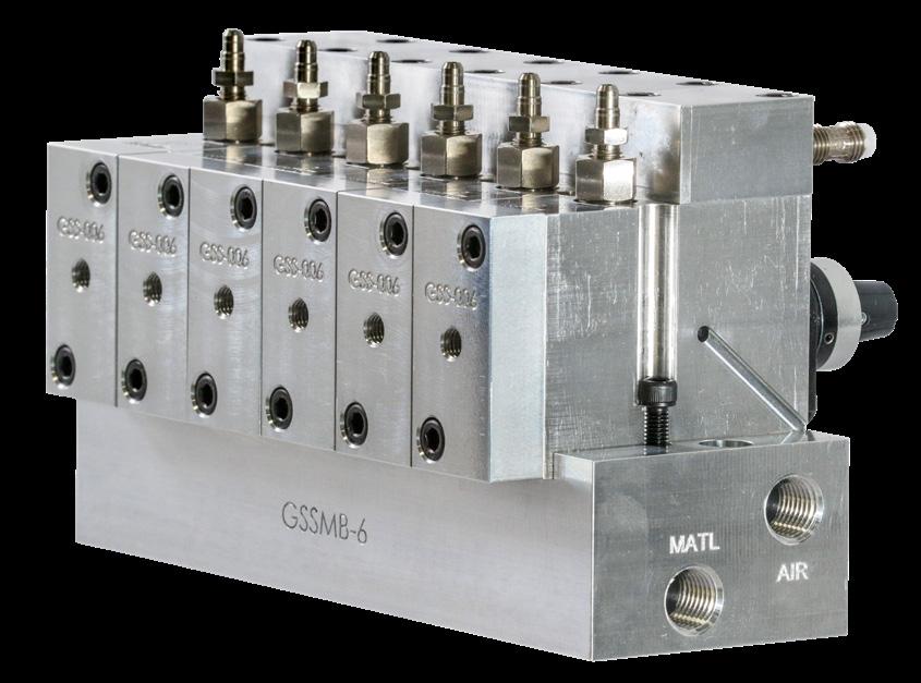
56 | gpreeves.com Reference DISPENSE PATENT Manufactured Under US Patent Number 6,053,285 This patent is only used on the GUS, Pump/GUS, and AA products. The GUS and Pump/GUS units find and remove the air before feeding downstream dispensers. The AA dispensers find and remove air during the dwell time or in between dispense cycles. Purge valveDispense / transfer valveFill valve orretractedrodMetering(shownfull) Linear position sensor — monitors air piston position to provide PLC input. PLC is used to determine compression test results. Air cylinder Air pistonCycleOverviewSteps Fill the chamber — open fill valve and allow material to push the metering rod back to the full position. Dispenser shown full of materialXX XX MaterialXO“O”point, Full


© 2022 | 57 XXX XXO X XX Test the material in the chamber — push the metering rod into the chamber full of material. Compression test shown without an air bubble. Compression test shown with an air bubble If compression within tolerance, dispense material — open dispense valve and push material out the dispense port If compression above tolerance, purge material — open purge valve and push material out the purge port Material Normal compression point / within tolerance Compresses more than normal / above toleranceAir Bubble Air Bubble XO XMaterial Reference
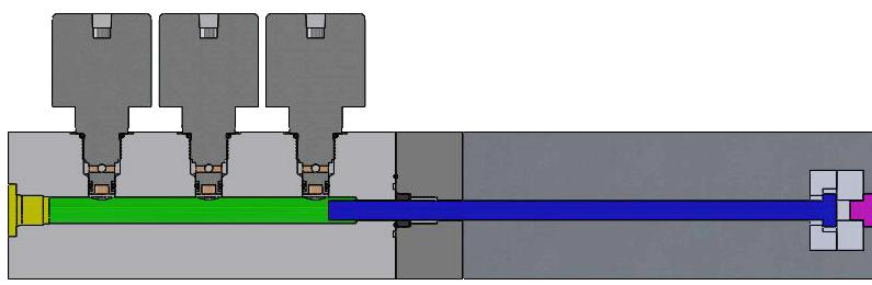


58 | gpreeves.com GREASE VOLUME The Paraboloid is a Natural Grease Dispense Shape Grease volume is often expressed in cubic inches (“³) and cubic centimeters (cc). Cubic centimeter is also known as milliliter (ml) and the terms are interchangeable. Grease weights (often expressed in grams) can be converted to cc and ml (volume) by dividing the weight by the specific gravity of the grease. Example: The volume of one gram (weight) of grease with a specific gravity of .88 is 1.14 cubic centimeters (1 / .88 = 1.136 cc). Formula for Paraboloid Volume: V = .3927d2 h, V = volume | d = diameter | h = height The photo above shows the parabolic shape that often occurs when grease is extruded onto a flat surface from an open orifice type nozzle with the nozzle pulled away after grease was dispensed. The volumes shown on the right are based on the height and diameter being equal. Application Visuals on U.S. Dimes Volume in cubic inches and centimeters)(cubic Height in inches and (mm) Diameter in inches and (mm) .001 (.016) .137 (3.48) .137 (3.48) .002 (.033) .172 (4.37) .172 (4.37) .003 (.049) .197 (5.00) .197 (5.00) .004 (.066) .217 (5.51) .217 (5.51) .005 (.082) .234 (5.94) .234 (5.94) .006 (.098) .248 (6.30) .248 (6.30) .007 (.115) .261 (6.63) .261 (6.63) .008 (.131) .273 (6.93) .273 (6.93) .009 (.147) .284 (7.21) .284 (7.21) .010 (.164) .294 (7.47) .294 (7.47) .011 (.180) .304 (7.72) .304 (7.72) .012 (.197) .313 (7.95) .313 (7.95)0.000364 cc spots 0.066 cc spot 0.131 cc spot Grease Volume Based on Sphere Diameter Formula: V = 4πr³/3 | V = volume, r = radius The sphere is not a natural grease dispense shape, but it is included because it is familiar. Example: The 0.177 caliber (4.5 mm) diameter of a BB and a 1/4” diameter ball bearing are easily visualized by many. Diameter in inches and (mm) Volume in cubic inches and centimeters)(cubic 0.062 (1.57) 0.000125 (0.0205) 0.125 (3.18) 0.0010 (0.0164) 0.177 (4.50) 0.0029 (0.0475) Diameter in inches and (mm) Volume in cubic inches and centimeters)(cubic 0.1875 (4.76) 0.00345 (0.0565) 0.25 (6.35) 0.0082 (0.1343) 0.38 (9.65) 0.0287 (0.470) Reference


© 2022 | 59 VOLUME CONVERSION CHART 0.000364 cc on a dime 0.066 cc on a dime 0.131 cc on a dime To Convert From: Into: Multiply By: GALLONS Quarts 4.0 Pints 8.0 Ounces 128.0 Cubic inches 231.0 Cubic centimeters 3,785.0 Drops 112,920 To Convert From: Into: Multiply By: CUBIC INCHES Gallons 0.00433 Quarts 0.01732 Pints 0.0346 Ounces 0.554 Cubic centimeters 16.39 Drops 490.0 To Convert From: Into: Multiply By: QUARTS Gallons 0.25 Pints 2.0 Ounces 32.0 Cubic inches 57.75 Cubic centimeters 946.52 Drops 28,230 To Convert From: Into: Multiply By: CENTIMETERSCUBIC Gallons 0.000264 Quarts 0.00105 Pints 0.0021 Ounces 0.03381 Cubic Inches 0.061 Drops 30.0 To Convert From: Into: Multiply By: PINTS Gallons 0.125 Quarts 0.5 Ounces 16.0 Cubic inches 28.87 Cubic centimeters 473.179 Drops 14,115 To Convert From: Into: Multiply By: DROPS Ounces 0.00113 Cubic inches 0.002 Cubic centimeters 0.033 To Convert From: Into: Multiply By: OUNCES Gallons 0.00781 Quarts 0.03125 Pints 0.0625 Cubic inches 1.805 Cubic centimeters 29.57 Drops 885.0 To Convert From: Into: Multiply By: GRAMS (Based on Specific Gravity of 0.90) Cubic inches 0.0678 Cubic centimeters (AKA milliliter) 1.111 1.25 cc on a quarter 1/4” dia. x 4.50” lg. bead = 3.62 cc 3/8” dia. x 2.0” lg. bead = 3.62 cc 1/2” dia. x 1.125” lg. bead = 3.62 cc Reference

GP Reeves Inc. 4551 Holland Ave. Holland MI 49424 Fax:Phone:gpreeves.com888-399-8893616-399-8867 20220831


