
FEA and Motion on: How Engineering Simulation Reduces Production Risk
Learn how FEA and motion simulation are used in industrial machine design to identify structural failures and dynamic problems before manufacturing.
Building a machine to discover it fails structurally under load is expensive The steel has been cut, the components machined, the assembly completed Modifying the design at that point means rework, scrap, and schedule delay Finite Element Analysis, applied during the design phase, finds those failures before the first component goes to the machine shop
This is the practical case for simulation in machine design. Not theoretical the cost of finding a structural or kinematic problem in a CAD model is a fraction of the cost of finding it in a fabricated machine. Copyright © 2026 Gmd.Engineeing All rights reserved.
What FEA Actually Does
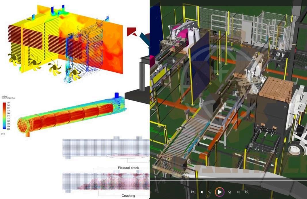
Finite Element Analysis is a computational method that simulates how a structure responds to applied loads The 3D geometry of a machine component is divided into a mesh of small elements, and the software solves the mathematical equations governing structural behavior across all those elements simultaneously
The output is a visual map of stress, strain, and deflection across the component under the specified loading conditions. High-stress regions appear clearly and high-stress regions that exceed the material yield strength indicate where the design will fail. According to engineering practice documented by the American Society of Mechanical Engineers, FEA has become a standard tool in the structural validation of industrial equipment precisely because it identifies failure modes that manual calculation methods can miss in geometrically complex structures
In practical machine design terms, FEA answers questions such as: will this lifting frame carry the rated load with an adequate safety factor? Will this conveyor cross-member deflect within acceptable limits under the weight of the product it carries? Will this welded joint transmit the load without fatigue failure over the machine's expected service life?
Global Machine Design Services performs FEA using Autodesk Inventor Stress Analysis, which is integrated directly into the 3D assembly environment This means the analysis is performed on the actual design geometry, not a simplified version built separately for simulation purposes
Readers looking for the broader engineering workflow can explore the Machine Design Engineering Hub for additional background on CAD, documentation, and design validation.
Copyright © 2026 Gmd.Engineeing All rights reserved.
Motion Simulation and W
FEA addresses structural behavior Motion simulation addresses kinematic and dynamic behavior how the components of a mechanism move, what forces are generated at joints and actuators, and whether the mechanism functions as intended across its complete operating range
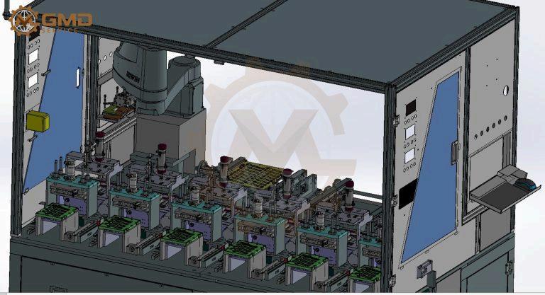
For machines with moving elements, motion simulation is the verification step that confirms the mechanism actually works before it is built. A packaging machine with cam-driven actuators needs to deliver the correct stroke at the correct timing without creating excessive joint loads. An automated assembly station with pneumatic grippers needs to reach every position in its work envelope without collision A robotic palletizing system needs to move its end effector through a programmed path without the linkage jamming or over-travelling its limits
Motion simulation identifies these issues in the model The correction is made in Autodesk Inventor The machine is then built, and it works
The alternative is to discover these issues during commissioning. Commissioning failures on automated equipment particularly robotic or cam-driven systems are expensive to diagnose and correct on the machine floor.
This workflow is commonly integrated into complete engineering projects delivered by GMD Engineering for industrial manufacturers
When Simulation Should Happen in the Design Process
The timing of FEA and motion simulation within the design sequence affects how useful the analysis is
Simulation performed before manufacturing drawings are finalized is the correct stage. At that point, the 3D design is complete enough to run a meaningful analysis, and any structural modifications can be made in the model and reflected in the drawings before manufacturing begins The correction cost is zero beyond the engineering hours required Copyright ©
Simulation performed as an aftertho ave been released to manufacturing is less useful Changes at that stag q g sions, potential component redesign, and in some cases scrapped material if parts have already been cut
Simulation performed too early, before the design is geometrically stable, produces results that will change as the design develops and may need to be repeated.
The practical recommendation is to schedule FEA and motion simulation as a formal stage in the design process, following detailed design completion and preceding drawing release Teams that treat simulation as a checklist item at the end of the project get less value from it than teams that build it into the design review workflow
What a Simulation Deliverable Looks Like
When Global Machine Design Services performs FEA or motion simulation for a client project, the deliverable is not just a pass or fail result The output includes:
The stress distribution visualization showing maximum and minimum stress locations across the component or assembly
Quantified safety factor for the critical load case the ratio of the material's yield strength to the maximum calculated stress Standard machine design practice targets a minimum safety factor of 2 0 to 3 0 for static loads, with higher factors for dynamic or fatigue loading
Deflection analysis showing maximum displacement under load, which is particularly relevant for precision equipment where deflection affects measurement accuracy or product quality.
For motion simulation, joint force plots showing the forces on each connection point throughout the mechanism's operating cycle, which informs actuator selection and bearing sizing
A clear statement of what was analyzed, what loading was applied, and what the results indicate. The simulation results are explained in the context of the design, not delivered as a data file for the client to interpret independently.
Applying Simulation to S Types
Different machine types present different simulation priorities
Lifting and handling equipment carries structural loads that make FEA non-optional. Gantries, hoists, and lifting frames designed without structural analysis present liability exposure for the manufacturer and safety risk for the end user.
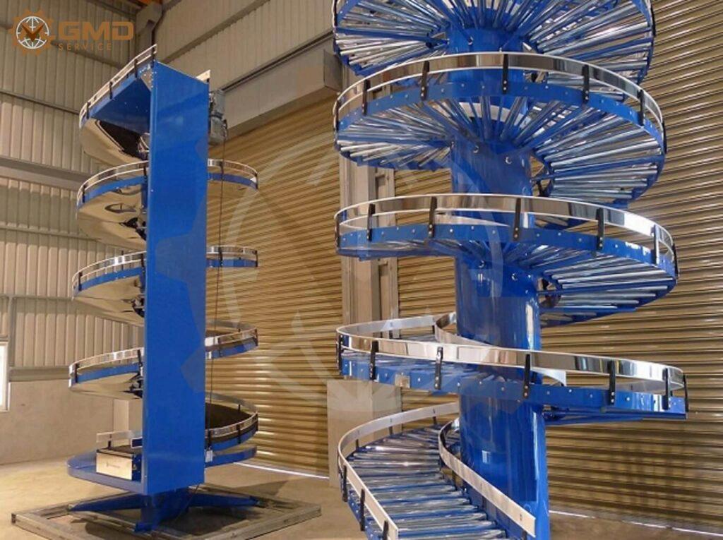
Conveyor systems require deflection analysis on cross-members and frame elements, and dynamic analysis on drive systems to confirm that the drive specification handles the inertia of a fully loaded belt or chain
Automated assembly machines require motion simulation to verify actuator timing, collision clearance, and reach envelope before commissioning.
High-speed packaging machines require dynamic load analysis to confirm that the structure can withstand the cyclical loads generated by high-speed cam mechanisms without fatigue failure over the machine's service life
What This Means for Your Engineering Project
Including FEA and motion simulation in a machine design engagement is not additional cost for its own sake It is a specific engineering activity that reduces the probability of discovering structural or kinematic problems in a fabricated machine at a point when fixing them is significantly more expensive.
For manufacturers commissioning custom machine design, specifying simulation requirements as part of the project brief ensures the engineering firm treats it as a design deliverable, not an optional extra
Global Machine Design Services provides FEA and motion simulation as an integrated part of the design process across conveyor systems, lifting equipment, automated assembly machines,
and packaging machinery Visit gmd an engineering consultation or review the complete machine design p
The complete machine development process is also discussed in the Custom Machine Design Services guide FAQ
What
is FEA in machine design?
Finite Element Analysis (FEA) is a computational method used to simulate how a machine component or structure responds to real-world loads, stresses, and environmental conditions In machine design, FEA identifies areas of high stress concentration, predicts deflection under load, and validates that a structure will perform safely within its design envelope before any physical component is manufactured
What is the difference between FEA and motion simulation?
FEA analyzes the structural response of a component or assembly to applied loads, identifying stress, strain, and deflection. Motion simulation analyzes the kinematic and dynamic behavior of a mechanism, evaluating how components move, what forces are generated at joints and actuators, and whether the mechanism performs as intended across its full range of motion In complex machine design, both types of simulation are often performed together
When should FEA be performed in the machine design process?
FEA should be performed after detailed 3D design is complete and before manufacturing drawings are finalized Running simulation at this stage allows structural modifications to be made in the CAD model without incurring manufacturing costs. FEA performed earlier in conceptual design can also be useful for comparing structural options, though the model does not need to be fully detailed at that stage.
Additional engineering references are available through the Engineering Documentation Library