8 minute read
Pipeline design with water hammer in mind

Pipeline
design with water hammer in mind
Advertisement
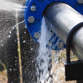
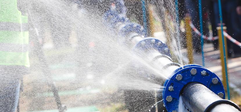
Water hammer can cause significant damage to pumps, valves and instruments, failure of gasketed joints and expansion joints, the deterioration of pipe walls and welded joints, and damage to pipe fittings – which all results in water leaks. But what is water hammer, and how can it be minimised when designing pipeline systems?
By George Gerber, CEO, Water Sanitation Engineering*
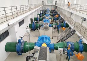
Water, sanitation and process industries usually transport liquids or gases from one location to another through a pipeline system. Pipeline systems typically comprise a combination of storage tanks, pumps, valves, pressure vessels, transmission pipelines and distribution or collection networks.
The design of these systems is normally based on expected or specified steadystate flows and pressures. Pipeline systems cannot, however, be permanently operated in a steady-state condition because occasional events, such as power failures, or recurring events, such as pump starts, will change the velocity of the flow.
This leads to an interchange between the kinetic energy of the flow and the strain energy in the fluid and pipe wall, altering the fluid pressure and the stress inside the pipe wall. This energy is ultimately dissipated through frictional losses in the fluid and in the pipe wall. Sometimes, the pressure changes are dramatic, representing hammer-like blows to the piping system. Hence the names ‘water hammer’, ‘surge’ or ‘transient’ are given to this phenomenon when it is observed in the field.
Consequences
Water hammer events create unwanted health and safety, environmental, legal and financial consequences that range from mildly inconvenient to disastrous. These consequences are often unforeseen during the front-end design and do not become apparent until long after the event. They depend on the magnitude of the pressure changes, the duration for which system components are exposed to them, and the speed with which they occur.
Examples of the hazardous conditions caused by water hammer include: • Excessive pressures, leading to permanent deformation or rupture of the pipeline; damage to pumps, valves, joints, seals, and anchor blocks; and leakages out of the pipeline causing wastage, environmental contamination, or fire hazards in the case of oil and gas pipelines. • Insufficient pressures, leading to collapse of the pipeline; disintegration of cement linings; creation of damaging pressure spikes when the water columns on opposite sides of a collapsing vapour cavity reconnect; contamination of the transported liquid by drawing in groundwater or air through joints and
The principal causes of hazardous conditions due to water hammer are the magnitude of the pressure changes, the duration for which system components are exposed to them, and the speed with which they occur
seals; or the creation of fire hazards when air is sucked into oil and gas pipelines. • Insufficient velocity, leading to settlement and line blockage of entrained solids, as well as increased pumping energy and maintenance costs. • Reverse flow, causing damage to pump seals and motors, draining of storage tanks and reservoirs, as well as increasing the magnitude of velocity and pressure changes in the case of slow-closing nonreturn valves. • Pipeline movement and vibration, causing overstressing and failure of supports, leading to pipeline failure and damage to adjacent equipment and structures.
Risk assessment
No two pipeline systems are the same and there is no universally applicable solution to water hammer problems. Every pipeline must be assessed individually, and a suitable surge control strategy selected accordingly.
The risk posed by water hammer should be assessed at the conceptual design stage, prior to finalising the pipe material, diameter and wall thickness, as well as at the technical design stage, prior to detailing the mechanical and electrical plant to ensure maximum safety and economy of the pipeline project. The first step in a risk assessment exercise is to define the system and its safe operating limits. This is followed by a brainstorming exercise, supported by a checklist, to identify the potential hazards and threats, to and from a pipeline, arising from water hammer.
The following ‘what if’ questions could serve as an aid in identifying potential hazards and threats: • What if the power fails to the motors driving the pumps? • What if a pump is restarted shortly after being tripped? • What if a control or emergency shutdown valve is rapidly closed? • What if an operator opens any of the valves too quickly? • What if the pipeline route is changed or portions are isolated for maintenance? • What if the demand on the system is increased?
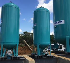
Vertical air vessels comprise a closed vessel partly filled with gas and connected to the pipeline. During a surge event, liquid is allowed to enter the vessel, which compresses the gas and gradually brings the liquid to rest (Photo credit: Charlatte Reservoirs)
Surge control
Once all the potential threats have been identified, they should be reviewed to determine those that represent the critical design case. A surge control strategy should then be devised to protect the pipeline system against the critical threats. Such a strategy will likely also cover the other threats.
The control strategy may include one or more of the following: • Stronger pipes, which increase the pressure rating of the pipeline, may be the only option in some instances.
For example, where complete containment of hazardous fluids is of paramount importance. • Re-routing can reduce or even eliminate some hazards, such as rising mains that follow a lower route to avoid sub-atmospheric pressures following a power failure. • Changing valve movements, such as increasing valve closure times, can lead to a reduction in the magnitude of pressure changes. Regular inspection and maintenance of flow control valves is also essential to prevent the risk of hunting either by interacting with other similar components or slackness due to worn parts. • Irregular spacing of pipe supports on long stretches of pipe can prevent resonance hazards by ensuring that natural vibration frequencies of adjoining sections do not coincide. • Relief valves will open when the pressure exceeds a set pressure, allowing the fluid to escape from the pipeline. • Air valves will open and admit air into the pipeline when the pressure inside the pipeline drops below atmospheric, avoiding the formation of hazardous vapour cavities. • Check valves will prevent reverse flow and the rotation of pumps, and can
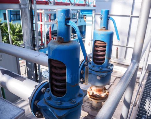
Pressure-relief valves will open when the pressure exceeds a set pressure and allow the fluid to escape from the pipeline
isolate sections of a pipeline from large pressure rises following the collapse of vapour cavities. • Feed tanks can reduce negative pressures when air admission is unacceptable. • Surge shafts can be used to reroute flow if a sudden change in pressure is likely. • Air vessels can be used when the required height of a surge shaft becomes impractical. Liquid is allowed to enter a closed vessel partly filled with gas, while the incoming liquid compresses the gas and gradually brings the liquid to rest. • By-passes can be fitted around a pump to admit water from the sump when the pump trips on a pipeline that has a low static head. • Accumulators or flexible hoses can be used in small systems to eliminate resonance hazards by damping flow pulsations. The following questions could serve as a guide to identify the most appropriate surge control strategy: • Where is the water hammer event initiated? At the upstream end, downstream end, or at an intermediate location? To be most effective, the selected surge protection device should be located at or as near as possible to the location where the water hammer event is initiated. • Does the pressure rise or drop initially? • Can a bypass device help? • Could secondary devices (e.g. air valves) elsewhere in the system be of benefit?
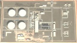
BELOW Sixteen vertical air vessels installed on the discharge side of a water transmission pumping station (Image credit: Google Earth) BOTTOM Vertical air vessels installed on the suction and discharge sides of a water transmission pumping station (Image credit: Google Earth Design considerations

Determination of the required thickness of the pipe wall for a new installation requires special consideration of the pipe material, diameter and internal working and surge pressures.
For instance, the American Water Works Association’s design guide for steel pipes recommends that different allowable design stresses be used for working and surge/test pressures when determining the wall thickness. The PVC and PE design guides recommend that the pipe pressure class be derated when determining the pipe wall thickness if the sustained operating temperature exceeds 23°C. They also recommend that recurring and occasional surge pressures be considered separately, since these pipes may eventually fatigue if exposed to continuous cyclic surging of a sufficiently high frequency and stress amplitude.
Special consideration should also be given to the wave propagation speed, as it has a direct bearing on the magnitude of the surge pressure and can vary considerably, according to the physical properties of the liquid and the pipe, as well as the amount of entrained air or other gases in the liquid. For example, water without entrained air in plastic pipes generally has a wave speed of 500 m/s, while the wave speed can exceed 1 000 m/s for steel pipes.
Furthermore, water hammer calculations must be based on the maximum flow of the pipeline system, rather than on the design flow. When determining the maximum flow, it should be remembered that new pipes have lower frictional losses than old ones and that a pump may deliver more flow against a given head than indicated by the manufacturer’s characteristics.
Pipeline systems typically comprise a combination of storage tanks, pumps, valves, pressure vessels, transmission pipelines and reticulation networks for the distribution or collection of liquids or gases
Importance of testing
Conducting a field survey upon completion of an installation in a new construction should be considered an
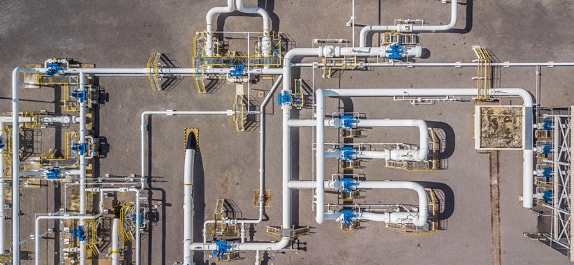
The check valves with yellow counterweights will prevent reverse flow and rotation of pumps. Check valves can also isolate sections of a pipeline from large pressure rises (Photo credit: AVK Valves)