9 minute read
The

from IMIESA June 2023
by 3S Media
Intricacies Of Landfill Development
What’s behind the design?
Advertisement
Part 2 of 2
Landfill design and construction is a multifaceted process that requires expert knowledge to ensure environmental compliance and maximum operational life. In the following commentary, Envitech Solutions’ Kris Matulovich (KM), associate director, and Molly McLennan (MM), senior design engineer, provide technical explanations to common questions concerning engineered municipal general waste landfills.
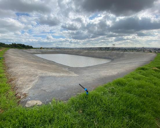
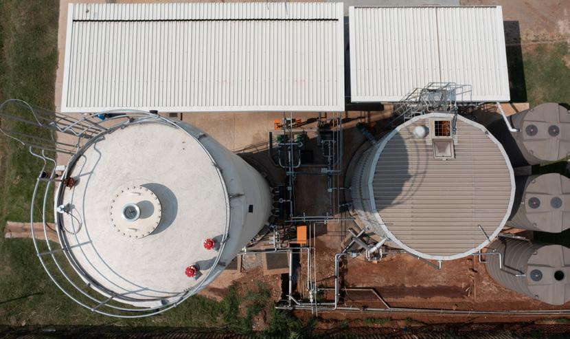
How do you size the leachate dam?
MM The primary criterion for determining the dimensions of the leachate dam is to ensure its ability to accommodate the 1:50year, 24-hour storm run-off from the operating cells within the landfill. In order to achieve this, several factors must be taken into consideration. First, an allowance needs to be made for any existing water present in the dam, which may vary depending on the specific operations at the site. Additionally, the rainfall depth associated with such a storm event in the particular region must be determined.
The calculated total capacity required serves as the basis for finalising the geometry of the dam. However, the depth may be limited by the prevailing ground conditions, such as the presence of hard rock or water table level. The length and breadth of the dam are typically determined by the site conditions. In terms of cost-effectiveness, square or rectangular shapes are often preferred.
By carefully considering the factors mentioned above, the dimensions of the leachate dam can be determined to ensure it can adequately accommodate the run-off from the specified storm event. This is crucial for the proper functioning and containment of the leachate within the landfill, thereby minimising the risk of environmental contamination.
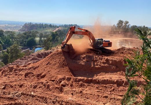
What happens to the material excavated from the landfill site?
MM During the excavation of cell bases in landfills, the excess cut material is typically stockpiled for various purposes. This material is utilised for activities such as daily cover, stability berms during lifting procedures, and capping/shaping of the landfill upon closure.
It is crucial to conduct a rigorous materials balance to assess the availability of material for these operations and to determine whether external off-site material will be required in the future.
In cases where additional material is needed, builders’ rubble and other inert waste streams can be considered as potential sources of cover material. These materials can be utilised effectively to fulfill the requirements of daily cover and other necessary purposes.
The construction of perimeter berms for the landfill cell and dam is usually carried out through a cut-to-fill process. This involves excavating the required material from one area and using it to fill and shape the berms. The fill material is compacted appropriately to achieve the desired compaction level, ensuring the stability and integrity of the landfill cell.
By carefully managing the excavation process and stockpiling the excess cut material, landfills can ensure a controlled and efficient use of available resources. This approach facilitates the proper functioning and long-term sustainability of the landfill by minimising the need for external material sourcing and optimising the utilisation of on-site resources.
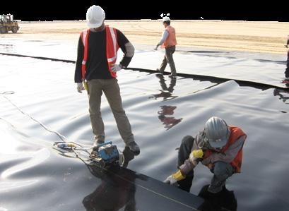
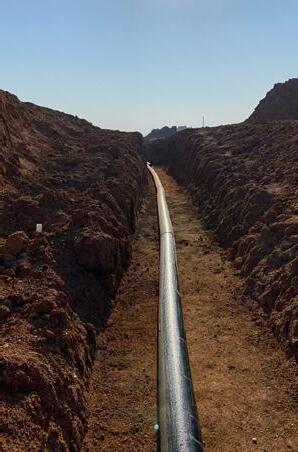
What makes up the liner system and why?
KM The primary objective of the liner system in a landfill is to establish a robust barrier that effectively separates the waste or waste leachate from the surrounding environment. While it is acknowledged that all liners may experience some degree of leakage, it is imperative that such leakage remains minimal throughout the entire lifespan of the landfill. Achieving this goal necessitates the use of suitable materials, correct installation practices, and diligent supervision and quality control. Furthermore, continuous leakage monitoring is essential throughout the operational life of the landfill.
The key component of the liner system is the high-density polyethylene (HDPE) geomembrane.

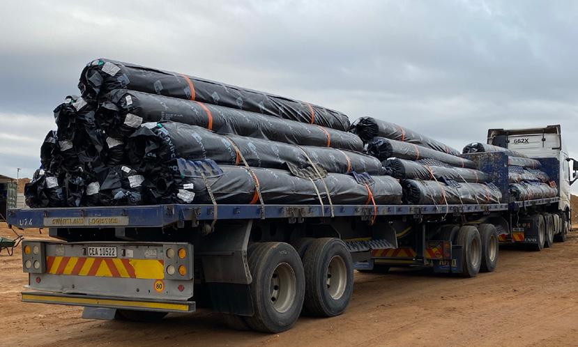
Depending on the waste category and the type of landfill facility, clay layers may also
Welding of the geomembrane liner sections should only be carried out by specially trained experts be incorporated into the barrier system. Permeability tests must be conducted on the available clay material to ensure that its permeability does not exceed 1 x 10⁻⁷ cm/s (as stipulated in the relevant norms and standards). If appropriate clayey material is not available, a geosynthetic clay liner (GCL) can be used, provided that testing demonstrates equivalent barrier performance. A drainage layer is required beneath the geomembrane to facilitate leakage detection. This drainage function can be fulfilled by either a layer of aggregates or a geosynthetic alternative such as a cuspated HDPE sheet drain.
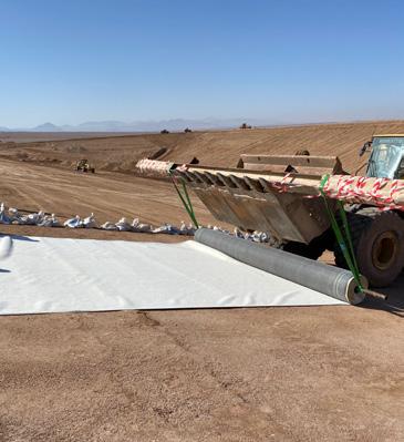
Geotextiles play two vital roles in the liner system. They serve as a separation layer between coarser and finer materials, and as a protection layer, which requires a thicker geotextile. All the liner materials comprising the barrier system must undergo individual conformance testing, as well as comprehensive testing as a unified system, particularly in terms of shear strength and protection efficiency.
The design engineer may not specify a specific brand of product but should instead define performance parameters in accordance with project requirements and Geosynthetic Research Institute specifications.
What testing of the liner system needs to be undertaken?
KM To ensure the stability and effectiveness of the liner system in a Class B landfill for municipal solid waste (MSW), various tests are required for the individual liner components and their combined configurations. The following tests are typically anticipated:
Compatibility testing
If acceptable clay is not available, a GCL is used. Swell index testing is conducted using actual leachate from the landfill site. If the landfill is not established yet, the testing is carried out using common chemical components found in MSW leachate.
Protection efficiency testing
The control of strain values within geomembrane liners is crucial, with a maximum limit of 3% deemed acceptable.
The primary source of strain on the geomembrane liner is attributed to the leachate collection or leakage detection aggregates employed in the Class B facility. These aggregates present the highest risk of inducing strain on the geomembrane liner. To mitigate the strains, the installation of a protection geotextile layer between the geomembrane and aggregate layer is necessary.
To assess the effectiveness of strain reduction, protection efficiency testing is conducted by an accredited international laboratory. This testing involves subjecting the entire lining barrier system to specified loads determined by the design engineer. If the strain on the geomembrane exceeds the allowable 3%, adjustments need to be made. This can involve increasing the density of the protection geotextile and retesting. Alternatively, altering the size, uniformity and angularity of the aggregates can also impact strain levels on the geomembrane liner.
Based on our findings, the use of a uniform 37.5 mm aggregate generally necessitates a 1 000 g/m2 protection geotextile, while larger or non-uniform aggregates of 22-34 mm may require a 1 200 g/m2 geotextile. It is important to note that the cost difference between these two types of protection geotextiles can range from
All the liner materials comprising the barrier system must undergo individual conformance testing, as well as comprehensive testing as a unified system, particularly in terms of shear strength and protection efficiency
R8.00 to R10.00 per m2. Considering the coverage area of a landfill cell, this cost variation can have a significant impact. Therefore, the design engineer should carefully specify lining and aggregate components that not only ensure an effective barrier system but also prove to be cost-effective.
To ensure the suitability and performance of the lining configurations employed in the proposed landfill, protection efficiency testing must be conducted on all utilised configurations. The imposed loading specified by the engineer typically aligns with the maximum height of the landfill, with the greatest loading occurring at the basal area. This loading is then multiplied by an estimated bulk density of 1.5 t/m3. A factor of safety of 1.3 is applied to the resulting confining pressure to determine the final pressure used in the testing process.
Shear box testing
Shear box testing is a critical step in evaluating the interface friction between different lining elements in a landfill. It helps determine the coefficient of interface friction (COF) and cohesion of the lining combinations, which are essential parameters for slope stability, global stability and veneer stability calculations.
Interface friction refers to the resistance to sliding or movement that occurs at the interface between different materials within the landfill liner system. This friction is a crucial factor in landfill design, as it directly impacts the stability, integrity and effectiveness of the liner system in preventing the leakage of pollutants into the surrounding environment. When subjected to external forces like differential settlement, slope instability or internal waste pressures, the liner materials can experience shear stresses along their interfaces.
The COF quantifies the interface friction and represents the ratio of the shear stress at the interface to the normal stress acting perpendicular to the interface. It depends on factors such as the roughness, surface properties and compaction of the materials, as well as the applied normal stress.
A higher COF indicates a stronger resistance to sliding, indicating better stability and performance of the liner system.
It helps prevent separation or sliding of the liner materials, ensuring the integrity of the barrier and minimising the risk of contaminant migration.
In a Class B landfill application, it is typically designed for the COF between the geotextile and geomembrane to be lower than the COF between the geomembrane and GCL. This design approach ensures that in the event of a failure, the geomembrane liner remains intact while slippage occurs on the protection geotextile. To further enhance the COF between the geomembrane and GCL, a textured HDPE liner can be specified with the textured face placed downwards, providing additional friction.
By conducting shear box testing and considering factors such as protection efficiency and COF, the design engineer can make informed decisions regarding the selection of appropriate lining and aggregate components. This ensures the establishment of an effective and cost-efficient barrier system for the landfill.
What engineering analyses need to be undertaken?
KM To ensure the stability of the proposed landfill, slope stability analysis is conducted, and the calculations are included in the submission to the regulator. The input parameters for the analysis are based on recent laboratory test results and previous experience with similar projects. These parameters will be verified during construction to ensure the correct selection of geosynthetic materials for the liner system.
In terms of interface friction, the critical interface for a Class B landfill is identified as the smooth HDPE geomembrane/protection geotextile interface on the landfill base.
The stability analysis is performed using GEO5 2023, a slope stability program that calculates the stability of slopes and embankments with circular or polygonal slip surfaces. For polygonal or non-circular slip surfaces, the program offers methods such as Sarma, Spencer, Janbu, MorgensternPrice, Shahunyants and ITF. The Sarma and Morgenstern-Price methods are commonly utilised for this analysis.
The Sarma method, developed in 1979, falls under the category of general sliced methods of limit states. It ensures force and moment equilibrium conditions for individual blocks created by dividing the region above the potential slip surface with planes of varying inclinations.
The Morgenstern-Price method, established in 1967, is a general method of slices based on limit equilibrium. It satisfies the equilibrium of forces and moments acting on individual blocks, which are created by dividing the soil above the slip surface with vertical planes.
During the modelling process, a water table is incorporated into the system at 300 mm above the landfill base to simulate a 0.3 m head of leachate within the leachate collection aggregate layer (worst-case scenario). It is important to note that shear box testing is also conducted using saturated lining components to test worst-case scenarios.
The output of the modelling must yield a factor of safety greater than 1.3 for the landfill to be considered acceptable.
Additionally, a veneer stability analysis is performed on the cell slope liner system according to the methodology of Soong and Koerner (2005), as described in Designing with Geosynthetics, 6th Edition by Robert M Koerner. A range of input parameters, derived from laboratory testing or assumed, is used to calculate the factor of safety. The analysis typically considers the full slope length of the landfill, excluding any benches, to ensure a conservative approach and enhance confidence in the stability of the landfill.
How does one ensure that all the liners, stone aggregates and soils are placed correctly and as per the design?
MM As per the requirements set by the regulator, the design engineer is obligated to submit a construction quality assurance (CQA) plan for the proposed landfill. This plan provides detailed specifications for the lining components and outlines the principles and practices of construction quality assurance to be followed during the installation of the specified liner materials. The plan also includes information regarding the frequency of confirmatory testing throughout the lining procedures. It serves as a guideline for the lining contractor during the landfill construction process.
Additionally, the client is responsible for appointing an independent CQA officer who will oversee the lining process in accordance with the design engineer’s CQA plan and data capturing sheets. The CQA officer’s role involves documenting all destructive testing conducted on-site, capturing photographs of the testing, and recording videos of activities such as material offloading and cell lining whenever possible.
It is important to note that while the independent CQA officer oversees the lining process, the ultimate responsibility for the landfill facility and barrier system remains with the registered design engineer. Therefore, strict site supervision of the construction activities, including earthworks and lining, is consistently carried out by Envitech, the designated party responsible for ensuring compliance with the design specifications and quality assurance protocols.
Responsible for the installation of over 20 anaerobic digestors in Africa, Talbot has extensive experience in building, designing as well as operating biogas plants, and is beginning to see an increase in biogas projects.

By Kirsten Kelly
