Rt. Hon. Herb Gray Parkway B arrie landfill reclamation Reference-free bridge damage identification Update: The New Champlain Bridge
2017 | SPRING/PRINTEMPS
RESILIENT INFRASTRUCTURE INFRASTRUCTURES RÉSILIENTES
www.csce.ca CIVIL.indd 1
2017-02-27 2:09 PM
Get more out of your Canadian Society for Civil Engineering membership. Get preferred insurance rates today!
Because you’ve earned it. Take advantage of your group privileges: You could save $415* or more when you combine your home and auto insurance with us.
At TD Insurance we believe your efforts should be recognized. That’s why, as a Canadian Society for Civil Engineering member, you have access to the TD Insurance Meloche Monnex program, which offers you preferred insurance rates and highly personalized service, along with additional discounts. Request a quote and find out how much you could save! Our extended business hours make it easy. Monday to Friday: 8 a.m. to 8 p.m. (ET) Saturday: 9 a.m. to 4 p.m. (ET)
Home and auto insurance program recommended by
HOME | AUTO
Ask for your quote today at 1-866-269-1371 or visit tdinsurance.com/csce The TD Insurance Meloche Monnex program is underwritten by SECURITY NATIONAL INSURANCE COMPANY. It is distributed by Meloche Monnex Insurance and Financial Services Inc. in Quebec, by Meloche Monnex Financial Services Inc. in Ontario, and by TD Insurance Direct Agency Inc. in the rest of Canada. Our address: 50 Place Crémazie, Montreal (Quebec) H2P 1B6. Due to provincial legislation, our auto and recreational vehicle insurance program is not offered in British Columbia, Manitoba or Saskatchewan. *Nationally, 90% of all of our clients who belong to a professional or an alumni group (underwritten by SECURITY NATIONAL INSURANCE COMPANY) or an employer group (underwritten by PRIMMUM INSURANCE COMPANY) that have an agreement with us and who insure a home (excluding rentals and condos) and a car on July 31, 2015 saved $415 when compared to the premiums they would have paid with the same insurer without the preferred insurance rate for groups and the multi-product discount. Savings are not guaranteed and may vary based on the client’s profile. ® The TD logo and other TD trade-marks are the property of The Toronto-Dominion Bank.
CIVIL_MelocheMonnex_Spring.indd 1 CIVIL.indd 2
Projet : Annonce MMI 2017
Province : Ontario Publication : Canadian Civil Engineer
Épreuve # : 1
2017-01-31 2:32 PM 2017-02-27 2:09 PM
nc.
an ups
1 2:32 PM
contents SPRING 2017/PRINTEMPS 2017 | VOLUME 34.1
IN VIEW: PROJECTS 12 The Parkway in a Prairie: The Rt. Hon. Herb Gray Parkway 14 Barrie Landfill Reclamation and Re-engineering FORUM ON SUSTAINABLE INFRASTRUCTURE/ FORUM SUR LES INFRASTRUCTURES DURABLES 10 Why and how CSCE is a leader in Sustainable Infrastructure
TECHNICAL: RESILIENT INFRASTRUCTURE/ TECHNIQUE: INFRASTRUCTURES RESILIENTES
17 Introduction: Bridging the gap with technical updates on structural
testing and new construction 18 Reference-free Damage Identification in Bridges using Relative Wavelet Entropy 22 The New Champlain Bridge: Technical Requirements and Delivery Status Report
18
NEWS, VIEWS & DEPARTMENTS NOUVELLES, POINTS DE VUE ET RUBRIQUES 4 President’s perspective/
Perspective présidentielle 6 From the regions: Atlantic/ Région de l’Atlantique 7 Student voice/La voix des étudiants 8 Young professionals corner/Le coin des jeunes professionnels 26 CSCE partners and sponsors/ Associés et commanditaires SCGC
22
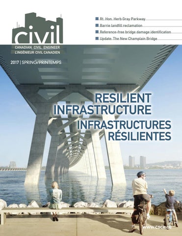
14 On the cover: Rendering of New Champlain Bridge from below deck
Canadian Civil Engineer | Spring 2017
CIVIL.indd 3
3
2017-02-27 2:09 PM
PRESIDENT’S PERSPECTIVE | PERSPECTIVE PRÉSIDENTIELLE
Jim Gilliland, Ph.D., P.Eng., LEED® AP PRESIDENT, CSCE/PRÉSIDENT SCGC PRESIDENT@CSCE.CA
CSCE/SCGC 521-300, rue St-Sacrement Montreal, Québec H2Y 1X4 Tel.: 514-933-2634, Fax: 514-933-3504 E-mail: mahmoud.lardjane@csce.ca www.csce.ca
PRESIDENT/PRÉSIDENT Jim Gilliland, Ph.D., P.Eng., LEED® AP
CANADIAN CIVIL ENGINEER/L’INGÉNIEUR CIVIL CANADIEN EDITOR/RÉDACTEUR Doug Salloum, CSCE Executive Director 514-933-2634 ext. 1, doug.salloum@csce.ca ASSOCIATE EDITOR/ RÉDACTEUR EN CHEF ADJOINT Doug Picklyk Tel.: 416-510-5119 dpicklyk@ccemag.com ADVERTISING SALES/ PUBLICITÉ Maureen Levy Tel: 416-510-5111 mlevy@ccemag.com
ART DIRECTOR/ COMPOSITION ARTISTIQUE Lisa Zambri Tel: 416-510-5600 x3595
Annual Subscription Rates/Abonnement annuel Canada & U.S./E.U. $35.00, Other countries/Autres pays $45.00; Single copy/Un numéro $7.50; Agency discount/Rabais au distributeurs 10% PUBLICATION ISSN 9825-7515 RETURN ADDRESS/ADRESSE DE RETOUR : The Canadian Society for Civil Engineering La Société Canadienne de Génie Civil 521-300, rue St-Sacrement Montreal, Québec H2Y 1X4 Canadian Civil Engineer (CCE) is published five times per year by the Canadian Society for Civil Engineering (CSCE). L’ingénieur Civil Canadien (ICC) est publié cinq fois par année par la Société Canadienne de Génie Civil (SCGC). The opinions expressed in the papers are solely those of the authors and the Canadian Society for Civil Engineering is not responsible for the statements made in this publication. Les opinions exprimées dans les articles sont la seule responsabilité de leurs auteurs et la Société canadienne de génie civil n’engage pas sa responsabilité dans les propos exprimés. CIVIL Magazine is produced by the publishers of Canadian Consulting Engineer Magazine, published by Annex Publishing & Printing Inc. Le magazine Civil est produit par l’editeur de la publication Canadian Consulting Engineer qui est publie par Annex Publishing & Printing Inc. Annex Publishing & Printing Inc., 80 Valleybrook Drive, Toronto, Ontario M3B 2S9 Tel.: 416-442-5600; Fax: 416-510-5140 PUBLICATIONS MAIL AGREEMENT/POSTES CANADA ENREGISTREMENT #40065710
4
CIVIL.indd 4
Communication is Everything
H
ow many times have we all heard the expression “Communication is everything.” Communication from the CSCE to its members and the public is necessary to inform everyone regarding issues relevant to civil engineers, as well as sustainability initiatives and innovations being developed across Canada and the around the world. The CSCE must continue to develop and enhance its arsenal of communication tools to remain relevant in our communities. The CSCE has many active committees and technical divisions that are working in specific fields of civil engineering or are interested in specific aspects of sustainable infrastructure. These committees represent many opportunities to contribute to the CSCE as well as to enhance your professional development and career objectives. Please review the committees on the csce.ca website and contact the committee chair if you are considering getting involved. The CSCE also has specific task forces and strategic initiatives that require volunteers to get things done. For example, we are currently working on a new communication “hub” for hosting all CSCE electronic resources, including technical databases. We also have a taskforce dedicated to promoting and developing a Canadian Sustainable Infrastructure Rating System. If either of these initiatives seem interesting to you, or if you have questions about the committees listed on our website, please contact me anytime. It’s easy for a CSCE member to get involved in the sustainability conversation—just ask! Get involved and be a part of growing Canada’s sustainable infrastructure. Volunteering with the CSCE to help enhance communications is an important role that provides great value for the CSCE as SUSTAINABLE well as the individual. This role helps promote the accomplishINFRASTRUCTURE IS: ments of CSCE members and also the relevance of the CSCE Meeting the needs of today without compromising the as a society. Equally as important, communication roles in the ability to meet the needs CSCE also raise the profile of the individuals taking their time of the future…balancing to volunteer and helps the individuals achieve their career goals. social, environmental and I believe that many current volunteers would agree with this pereconomic considerations. spective. It only takes a couple of hours to contribute something of value, whether it is time at lunch, or looking for interesting UNE INFRASTRUCTURE DURABLE C’EST : stories when you’re at home in the evening. Easy forms of comsatisfaire aux besomunication include short newsletters, social media postings, and ins d’aujourd’hui sans linking CSCE members to innovative sources of information compromettre la capacité around the world. Enhancing communications about CSCE acde satisfaire les besoins tivities is an easy way to learn about CSCE innovations without futurs...tout en équilibrant needing to be directly involved with academic research. les considérations sociales, environnementales et I hope to see everyone at the 2017 Annual Conference in Vanéconomiques. couver, and I’m looking forward to moving the conversation forward!
Printemps 2017 | L’Ingénieur civil canadien
2017-02-27 2:09 PM
PRESIDENT’S PERSPECTIVE | PERSPECTIVE PRÉSIDENTIELLE
Tout est une question de communication
C
ombien de fois avons-nous tous entendu l’expression « tout est une question de communication. » Les communications provenant de la SCGC et destinées à ses membres et au public sont nécessaires afin d’informer tout le monde sur des questions pertinentes aux ingénieurs civils, ainsi que sur les initiatives et les innovations en matière de durabilité qui sont élaborées au Canada et ailleurs dans le monde. La SCGC doit continuer à développer et améliorer son arsenal d’outils de communication afin de demeurer pertinente dans nos communautés. La SCGC comporte plusieurs divisions techniques et comités actifs qui travaillent au cœur de secteurs spécifiques du génie civil ou qui s’intéressent à des aspects particuliers des infrastructures durables. Ces comités représentent des occasions diverses de contribuer à la SCGC ainsi qu’à votre perfectionnement professionnel et vos objectifs de carrière. Veuillez consulter la liste des comités sur le site Web de la SCGC et contacter le président du comité concerné si vous souhaitez vous impliquer. La SCGC peut également compter sur des groupes de travail spécifiques et des initiatives stratégiques nécessitant des bénévoles pour faire avancer les choses. Par exemple, nous travaillons présentement sur un nouveau « pôle » de communication pour accueillir toutes les ressources électroniques de la SCGC, incluant les bases de données techniques. Nous avons également un groupe de travail dédié à la promotion et au développement d’un Système canadien de notation de la durabilité des infrastructures. Si l’une ou l’autre de ces initiatives vous interpellent, ou si vous avez des questions au sujet des comités, vous pouvez me contacter à tout moment. Il est facile pour tout membre de la SCGC de prendre part au débat sur la durabilité : vous n’avez qu’à demander ! Impliquez-vous et faites partie de la croissance des infrastructures durables au Canada. Être bénévole au sein de la Société dans le but de contribuer à améliorer les communications est un rôle important procurant une valeur ajoutée à la SCGC, ainsi qu’aux bénévoles. Ce rôle contribue à promouvoir les réalisations des membres de la SCGC ainsi que la pertinence de celle-ci en tant que société. Tout aussi importants, les rôles en communication au sein de la SCGC augmentent également la visibilité des personnes qui prennent de leur temps pour faire du bénévolat et aident ces personnes à atteindre leurs objectifs de carrière. Je crois que plusieurs bénévoles actuels partageraient ce point de vue. Cela ne prend qu’une couple d’heures pour faire une contribution importante ou pour rechercher des histoires intéressantes à partager, que ce soit sur l’heure du dîner, ou le soir, à la maison. Des formes simples de communication incluent de brefs bulletins d’information, des publications sur les médias sociaux et la communication de sources d’information innovatrices à travers le monde. Renforcer les communications sur les activités de la SCGC est une façon aisée d’en apprendre davantage sur les innovations de la SCGC sans être directement impliqué dans les recherches universitaires. J’espère vous voir au congrès annuel 2017 à Vancouver. J’ai très hâte de faire avancer le débat! VOLUNTEER SUSTAINABILITY WRITERS NEEDED: The CSCE is looking for volunteers to write brief (less than one page) articles that would be of interest to our members and the general public. These articles would not be scientific papers, but would promote interesting civil engineering initiatives and projects from anywhere in the world. Links to other sources or more detail can be used to make writing an article “a breeze”. No minimum or maximum number of articles is required from a writer. You don’t need to be an “expert”. You only need to love writing! Please contact me or the National office at your convenience to discuss further.
Canadian Civil Engineer | Spring 2017
CIVIL.indd 5
CSCE LEADERSHIP IN SUSTAINABLE INFRASTRUCTURE: FIVE ADVOCACY POSITIONS
1 Innovative Procurement Practices
2 Long-Term Investment Planning
3 Measure Sustainable Performance
4 Leverage Asset Management Processes
5 Sustainability Education LEADERSHIP DE LA SCGC EN MATIÈRE D’INFRASTRUCTURES DURABLES : CINQ PLAIDOYERS STRATÉGIQUES
1 Pratiques d’approvisionnement novatrices
2 Planication à long terme des investissements
3 Mesurer le rendement durable
4 Utiliser au mieux des processus de gestion des actifs
5 Enseignement de la durabilité
RÉDACTEURS BÉNÉVOLES EN DURABILITÉ DEMANDÉS: La SCGC est à la recherche de bénévoles pour rédiger de brefs articles (moins d’une page) qui pourraient être intéressants pour nos membres et le public en général. Ces articles ne seraient pas des exposés scientifiques, mais feraient la promotion d’initiatives de projets de génie civil intéressants d’un peu partout dans le monde. Des liens vers d’autres sources ou offrant davantage de détails peuvent être utilisés pour rendre l’écriture de l’article plus aisée. Il n’y a pas de minimum ou de maximum d’articles pouvant ou devant être écrits par un rédacteur. Vous n’avez pas besoin d’être un « expert ». Vous n’avez qu’à aimer écrire ! Veuillez me contacter personnellement ou encore le Bureau national pour en discuter plus en détail.
5
2017-02-27 2:09 PM
FROM THE REGIONS: SECTION NEWS | DE NOS RÉGIONS : NOUVELLES DES SECTIONS
T
Collaborating and growing in Atlantic Canada
La collaboration et la croissance dans le Canada Atlantique
Jeff H. Rankin, PhD, P.Eng, FCSCE
Jeff H. Rankin, PhD, P.Eng, FCSCE
VP ATLANTIC REGION, CSCE
V-P DE LA RÉGION ATLANTIQUE DE LA SCGC
L
a région atlantique de la SCGC englobe le secteur géographique he Atlantic Region of CSCE covers the geographic area of the des quatre provinces de l’Atlantique : Terre-Neuve-et-Labrador, la four Atlantic Provinces: Newfoundland and Labrador, Nova Scotia, New Brunswick and Prince Edward Island. Within the four Nouvelle-Écosse, le Nouveau-Brunswick et l’Île-du-Prince-Édouard. provinces, there are four Sections – Newfoundland and Labrador, Cette région comprend quatre sections, soit l’Est du Nouveau-BrunsEastern New Brunswick and Prince Edward Island, Western New wick et l’Île-du-Prince-Édouard, Terre-Neuve-et-Labrador, la Nouvelle-Écosse et l’Ouest du Nouveau- Brunswick. Brunswick and Nova Scotia. Les sections de Terre-Neuve et de l’Est du Nouveau-Brunswick conThe Newfoundland and Eastern New Brunswick Sections continue to offer events and support programming in line with the strategic tinuent d’offrir des activités en lien avec les orientations stratégiques directions of CSCE to support their local members and reach out de la SCGC afin de soutenir leurs membres locaux et de rejoindre to the broader civil engineering community, with great interactions la communauté plus large du génie civil. Ces activités comportent with their local Student Chapters at Memorial University and Uni- énormément d’interactions avec les chapitres étudiants locaux de versité du Moncton. A new event this year was a CSCE Section Fel- l’Université Mémorial et de l’Université de Moncton. Une nouvelle lows Dinner, an opportunity to recognize the contributions of CSCE activité cette année fut le dîner des membres Fellows de la section, une opportunité de reconnaître la contribution des membres Fellows Fellows and Career Awards recipients at a local level. In the Western NB and Nova Scotia Sections the theme continues de la SCGC et les récipiendaires des prix Carrière au niveau local. Les sections de l’Ouest du Nouveau-Brunswick et de la Nouto be growth. Western NB now has a very active executive offering a full program of events. Highlights of this past Fall include: the velle-Écosse mettent l’accent sur la croissance. NB Ouest peut industry-student dinner, led by the UNB Student Chapter, where maintenant compter sur un exécutif très actif offrant un programme CSCE past-president Tony Begin provided the keynote talk, sharing Suite à la page 7 his paths of personal and professional development to the over 70 practitioners and students in attendance; and an excellent technical talk was provided by Simon Bush, an Associate and Principal Engineer with Opus International, who shared his expertise on the topic of “The Next Generation of Asset Models.” Meanwhile, growth in the Nova Scotia Section has been focused on our younger members under the leadership of Section Chair, Haibo Niu (Dalhousie University), and YP Representative Chris Davis (City of Halifax) through partnerships with the Student Chapter and YP activities of Engineers Nova Scotia. The Atlantic Region Sections are working together to share best practices, and in the works is a collaboration on a Regional Speaking Tour surrounding the topic of Infrastruc- UNB Student Chapter Executive./La direction du chapitre étudiant de l’UNB où le président ture Sustainability Rating Systems for Canadi- sortant de la SCGC, Tony Begin, était le conférencier invité. an public infrastructure.
6
CIVIL.indd 6
Printemps 2017 | L’Ingénieur civil canadien
2017-02-27 2:09 PM
THE STUDENT VOICE | LA VOIX DES ÉTUDIANTS
Sneak Peek into Student Programming at Vancouver 2017
Suite de la page 6 complet d’activités. Les faits saillants de cet automne incluent : le dîner rencontre entre l’industrie et les étudiants, organisé par le chapitre étudiant de l’UNB, au cours duquel le président sortant de la SCGC, Tony Bégin, fut conférencier invité. Tony a partagé l’histoire de son parcours de développement personnel et de perfectionnement professionnel avec plus de 70 professionnels et étudiants présents à cet événement. De plus, un excellent exposé technique fut présenté par Simon Bush, associé et ingénieur principal d’Opus International, qui a partagé son expérience sur le thème de « la prochaine génération de modèles d’actifs. » Pendant ce temps, le président de la section de la Nouvelle-Écosse Haibo Niu (Université Dalhousie) et le représentant JP, Chris Davis (ville d’Halifax), ont mis l’accent sur nos plus jeunes membres par des partenariats avec le chapitre étudiant et les activités JP de Ingénieurs de la Nouvelle-Écosse. Les sections de la région atlantique travaillent ensemble afin de partager leurs meilleures pratiques. Elles collaborent entre autres à la tournée de conférences régionale sur le thème du système de notation de la durabilité des infrastructures publiques canadiennes.
Charles-Darwin Annan, Ph.D., P.Eng. CHAIR, STUDENT AFFAIRS COMMITTEE, CSCE
T
he local organizing committee for this year’s CSCE Annual Conference in Vancouver (May 31-June 3) is working hard to make the event unforgettable. CSCE Student Affairs is working with the Young Professionals (YP) team to put together a professionally stimulating program for students and YPs. Below is a sneak peek of some major events for students: National Student Chapter Leaders Workshop: This workshop will provide a stimulating platform for incoming CSCE Student Chapter leaders from across Canada to interact and exchange ideas. It will address topics such as keys to a dynamic student chapter, member recruitment and retention strategies, finances and fundraising strategies, member and faculty participation, setting SMART chapter goals and action plan, and the roadmap to becoming the best student chapter. National Civil Engineering Design Capstone Competition: The Capstone project is the cornerstone of many accredited civil engineering programs in Canada. Each civil engineering program will be invited to submit a nomination for a single entry into the competition in any specialty area. Two students from each nominated team will attend the conference and present their project in a poster session before a jury. The winner and runners-up will be announced at the Student Awards Luncheon. Student Paper Competitions: This competition presents an opportunity for students to share the results of their research projects. This year the competition will be held on a specialty conference basis, meaning each of the four specialty conferences will be recognising the top student papers. Student membership is required for eligibility. Student Awards Luncheon: This event will celebrate the achievements of our students from across the country. It also offers an excellent networking opportunity for students. Nearly 400 conference attendees participated in this event in London last year. Some of the awards presented Continued on page 8
Denso Products - Unmatched Quality and Performance
If it doesn’t say
on the outside, then its not
Denso North America Inc. • www.densona.com
Canadian Civil Engineer | Spring 2017
CIVIL.indd 7
on the inside.
7
2017-02-27 2:09 PM
THE STUDENT VOICE | LA VOIX DES ÉTUDIANTS Continued from page 7 will include the President’s Awards for Outstanding Student Chapters, Best National Capstone Design Awards, Best Student Paper Awards, and Awards for the Canadian National Concrete Canoe, Canadian National Steel Bridge, Great Northern Concrete Toboggan and Troitsky
Bridge Building Competitions. Check http://csce2017.ca/young-professionalsstudents/ Dr. Charles-Darwin Annan is an associate professor of civil engineering at Université Laval and can be reached at Charles-darwin.annan@gci.ulaval.ca
Coup d’œil à la programmation étudiante de Vancouver 2017 Par Charles-Darwin Annan, Ph.D., P.Eng PRÉSIDENT, COMITÉ DES AFFAIRES ÉTUDIANTES DE LA SCGC
L
e comité organisateur local du congrès annuel de cette année, qui aura lieu à Vancouver du 31 mai au 3 juin 2017, travaille d’arrache-pied pour faire de cette activité un événement inoubliable. Le comité des affaires étudiantes de la SCGC travaille avec l’équipe des jeunes professionnels (JP) pour créer un programme stimulant professionnellement pour les étudiants et les JP. Voici un aperçu des principales activités destinées aux étudiants : Atelier national des dirigeants des chapitres étudiants Cet atelier fournira une plateforme stimulante pour les dirigeants des chapitres étudiants de la SCGC de partout au Canada qui seront présents afin d’interagir et de partager leurs idées. L’atelier traitera de sujets tels que les clés d’un chapitre étudiant dynamique, le recrutement et la rétention des membres, les stratégies financières et de collecte de fonds, la participation des membres et du corps professoral, l’établissement des objectifs et du plan d’action SMART des chapitres, ainsi que la feuille de route pour devenir le meilleur chapitre étudiant. Concours national de conception Capstone en génie civil Le projet Capstone est la pierre angulaire de plusieurs programmes accrédités de génie civil au Canada. Chaque programme de génie civil sera invité à soumettre une candidature pour une participation unique au concours dans un domaine spécialisé. Deux étudiants/étudiantes de chacune des équipes candidates assisteront au congrès et présenteront leur projet sous forme d’affiche devant jury. L’équipe gagnante et les
finalistes seront annoncés lors du dîner de remise des prix étudiants. Concours de communication étudiante Ce concours donne aux étudiants une occasion de partager les résultats de leurs projets de recherche. Cette année, le concours aura lieu sur la base d’une conférence spécialisée, ce qui signifie que chacune des quatre conférences spécialisées reconnaitra aux meilleures communications étudiantes. Il faut être un membre étudiant de la SCGC pour prendre part à ce concours. Dîner de remise des prix étudiants Cette activité célébrera les réalisations de nos étudiants de partout au pays. Elle offre également une excellente opportunité de réseautage aux étudiants. Près de 400 congressistes ont participé à cette activité l’an dernier au congrès de London. Certains des prix qui seront remis incluront le Prix du président pour le meilleur chapitre étudiant, les prix du Concours national de conception Capstone, les Prix des meilleures communications étudiantes, ainsi que les prix du Concours national de canoë de béton, du Concours national de pont d’acier, de la Grande course nordique de toboggan de béton et du Concours de construction de ponts Troitsky. Veuillez visiter http://csce2017.ca/young-professionalsstudents/ Le Dr. Charles-Darwin Annan est professeur adjoint de génie civil à l’Université Laval et on peut le joindre à Charles-darwin.annan@gci. ulaval.ca
YOUNG PROFESSIONALS’ CORNER | LE COIN DES JEUNES PROFESSIONELS
Winter at the Young Professionals Committee
Bernard Moulins CHAIR, YOUNG PROFESSIONALS COMMITTEE, CSCE
8
CIVIL.indd 8
W
inter has struck and the CSCE Young Professionals Committee is finalizing the implementation of this year’s work plans and budgets. For 2017, we’ve prepared a plan to help achieve the National CSCE Vision 2020. This vision is composed of three strategic directions: enhanced member services, growing with youth, and leadership in sustainable infrastructure. Evidently, as we are the engineering leaders of the future, Young Professionals (YPs) continue to play a key role in fulfilling Vision 2020. In order to establish goals and direction for 2017, we first examined our performance in 2016. During the course of the last year, we rebuilt our YP Board, welcoming Vincent Tourangeau as Vice-Chair and
Printemps 2017 | L’Ingénieur civil canadien
2017-02-27 2:09 PM
YOUNG PROFESSIONALS’ CORNER | LE COIN DES JEUNES PROFESSIONELS Nicholas Kaminski as Treasurer. Together, we supported our national YP representatives in organizing a record-breaking number of events— succeeding in connecting YPs across the country. These events included networking cocktails, technical presentations and lecture series, all of which helped build a stronger community of Canadian Civil Engineers. We aim to maintain this momentum in 2017 by helping fund, organize, and promote CSCE YP events across Canada. We’ve already begun coordinating with the Edmonton YP representatives for a 2017 Speed Networking event, as well as with Vancouver’s Stanley Chan, our amazing 2017 CSCE Conference Coordinator, who’s helping create a YP
L’hiver au Comité des jeunes professionnels Bernard Moulins PRÉSIDENT, COMITÉ DES JEUNES PROFESSIONNELS, SCGC
L
agenda for the CSCE Annual Conference this Spring. We’re excited for new events, new members and more networking and growth opportunities for our YP members. As always, our key to success remains your feedback and involvement. We’re interested in creative ideas and happily welcome any new Committee members. Therefore, please share your thoughts with myself, Vincent or Nicholas. Any goals, events or ideas—big or small—are great. Don’t be shy and feel free to contact me directly at the email below. We hope you enjoy the great events and opportunities coming in 2017! Thanks for reading (bernard.moulins@enercon.de).
d’Edmonton. Nous sommes également en contact avec Stanley Chan (Vancouver), notre étonnant coordonnateur au congrès annuel 2017 de la SCGC, qui nous aide à créer un calendrier des JP pour ce congrès qui se tiendra ce printemps. Nous sommes emballés par les nouvelles activités, de l’ajout de nouveaux membres et de toutes ces occasions de réseautage et de croissance pour nos membres JP. Comme à l’habitude, la clé de notre succès est liée à vos suggestions et votre implication. Nous sommes intéressés par les idées originales et accueillons avec joie tous les nouveaux membres de notre comité. Venez donc partager vos idées avec Vincent, Nicholas et votre humble serviteur. Tout objectif, activité ou idée, qu’ils soient modestes ou ambitieux, sont les bienvenus. Ne soyez pas timide et contactez-moi directement à l’adresse courriel ci-dessous. Nous espérons que vous aimerez les belles activités et opportunités que nous organiserons pour vous en 2017 ! Merci de votre attention (bernard.moulins@enercon.de).
’hiver est arrivé et le comité des jeunes professionnels de la SCGC est en train de finaliser la mise en œuvre des plans de travail et des budgets de cette année. Pour 2017, nous avons élaboré un plan contribuant à réaliser la Vision 2020 de la SCGC au niveau national. Cette vision est constituée de trois orientations stratégiques : l’amélioration des services aux membres, la croissance avec les jeunes et le leadership en infrastructures durables. Évidemment, en tant que leaders du futur en ingénierie, les Jeunes professionnels (JP) continuent de jouer un rôle clé dans la réalisation de la Vision 2020. Afin d’établir des objectifs et une orientation pour 2017, nous avons tout d’abord passé en revue nos résultats de 2016. Au cours de la dernière année, nous avons modifié la constitution du Conseil RVA wins two awards from des JP, en accueillant Vincent Tourangeau Ontario Public Works Association comme vice-président et Nicholas Kaminski en tant que trésorier. Ensemble, nous avons soutenu nos représentants nationaux JP en organisant un nombre record d’activités et en réussissant à mettre en relation les JP à travers le pays. Ces activités ont inclus des cocktails de réseautage, des présentations techniques et une série de conférences. Toutes ces activités ont contribué à développer une communauté plus forte au sein des Project of the Year, Small Municipality Project of the Year, Structures Millbrook Water & Wastewater Expansion Denison Road Grade Separation ingénieurs civils canadiens. Township of Cavan Monaghan, ON Metrolinx, Toronto, ON Notre objectif est de maintenir cet élan en 2017 en contribuant à financer, organiser et promouvoir les activités JP de la SCGC partout au Canada. Nous avons déjà entamé la coordination d’une activité de réseautage toronto niagara ottawa sudbury london moncton fredericton st. john’s mumbai www.rvanderson.com express en 2017 avec les représentants JP CIVIL_RV Anderson_Spring17.indd 1
Canadian Civil Engineer | Spring 2017
CIVIL.indd 9
Canadian Civil Engineer 2017-02-03 3:38 PM 4.875” x 3.625” January 20179
2017-02-27 2:09 PM
SUSTAINABLE INFRASTRUCTURE | LES INFRASTRUCTURES DURABLES
Why and how CSCE is a leader in Sustainable Infrastructure By Doug Salloum EXECUTIVE DIRECTOR, CSCE
I
n our Vision 2020, published in 2010, CSCE committed to three new Strategic Directions. Strategic Direction #3, the most creative and bold of the three, committed CSCE to a position of leadership in sustainable infrastructure. Not all members, however, are on board with this strategic direction. Some are still unaware of our commitment to sustainable infrastructure and some have expressed reservations, asking: • Why focus on infrastructure? • How does CSCE define sustainable infrastructure? • What does CSCE mean by leadership? These questions came from our members, and therefore they are deserving of a reply. For every member who has asked these questions there are probably many more who have been thinking them. This article will attempt to reply to these questions.
Why sustainable infrastructure? During his term as CSCE President-elect in 2008 and as President in 2009, Vic Perry talked to CSCE members from coast to coast, asking them what they wanted from CSCE. The ideas collected were eventually captured in our three Strategic Directions, which have since become the framework for all CSCE strategic initiatives. The Board formulated Strategic Direction 3, Leadership in Sustainable Infrastructure, in response to two very specific demands. Our members want CSCE to: • Give Canadian civil engineers reason to be proud and; • Raise the public profile of civil engineering. Some members have argued that a focus on infrastructure, sustainable or otherwise, is too narrow, and that civil engineers are involved in more than infrastructure. Members who do not work in the municipal sector may not see themselves as having anything to do with infrastructure. Municipalities and other levels of the public sector certainly build what most people see as traditional infrastructure: waste treatment facilities, sewer lines, roads and highways, water distribution systems, bridges, etc., but the private sector also builds infrastructure. Office buildings, condos, hospitals, education and sports facilities as well as mines, oil fields, electrical generation facilities and many other private sector projects are all infrastructure projects under CSCE’s definition. Definition: Infrastructure is any man-made structure or system that delivers or maintains the basic physical needs of society.
10
CIVIL.indd 10
All civil engineering disciplines (from structures to materials, from hydrotechnical to geotechnical engineering) have a role in the creation of some of the infrastructure our country relies on. With this larger picture of what infrastructure is, it seems to me that everything civil engineers do relates to the design, construction, operation or maintenance of infrastructure, and all disciplines within civil engineering contribute. A commitment to better infrastructure therefore should be something all CSCE members can get on board with. That is a vision we can be proud of and a vision the public can understand and respect.
What is sustainable infrastructure? I offered a two-part definition of sustainable infrastructure in my editorial in the last issue of Canadian Civil Engineer. This is a working definition because the field is still relatively young. Definition: 1. Sustainable Infrastructure is infrastructure that lasts 2. Sustainable infrastructure is infrastructure that provides public benefit throughout its operating life
1. There are lots of examples of infrastructure systems in Canada and in other countries that have operated for more than 100 years. It is not unrealistic, therefore, when designing new infrastructure to think ahead seven generations, as First Nations leaders admonish us to do, and to plan for an operating life of 200 years or more. 2. When I refer to public benefit I mean benefit to people, whether the ownership is public or private, and by benefit I mean economic, social and environmental benefit. It is not enough to avoid negative social or environmental impacts. We should seek to deliver real environmental and social benefits with our infrastructure investments. Since operating life is also referred to in the second part of this definition, infrastructure that does not respond to long-term needs of society is not sustainable infrastructure. End-of-pipe solutions, like merely increasing the capacity of a road or sewage treatment plant, are often short-term solutions. The root causes of the increased demand need to be understood to develop long-term solutions to this demand. Not increasing capacity or not building the proposed infrastructure at all may be the better solution. This definition is meant to be inspirational. We need a definition that will inspire us to create better infrastructure. CSCE members want-
Printemps 2017 | L’Ingénieur civil canadien
2017-02-27 2:09 PM
SUSTAINABLE INFRASTRUCTURE | LES INFRASTRUCTURES DURABLES ed a definition of sustainable infrastructure, and I hope this definition-in-progress responds to that request. I also hope the definition will generate discussion amongst CSCE members.
What is leadership? In Vision 2020 CSCE stated a commitment to leadership in sustainable infrastructure. No other organization in Canada has made this same commitment. It is not enough to say we are leaders, however. We need to act like leaders, and CSCE has been doing just that. The following examples of leadership need to be recognized and celebrated by our members and eventually by the Canadian public. 2016 Winner of CSCE Award for Governmental Leadership in Sustain-
• Award for governmental leadership in sustainable infrastructure: CSCE set out to recognize and honour public sector decision makers who make the, often difficult, political decision to do better than business as usual when spending public funds for infrastructure. We have awarded this prize, which is an original piece of art by a different young artist, five times. The winners so far have been: • 2012 City of Edmonton, Risk-Based Infrastructure Management System (RIMS) • 2013 City of Quebec, St. Charles River Clean-up • 2014 Waterfront Toronto, West Don Lands Redevelopment • 2015 SaskPower, Boundary Dam Integrated Carbon Capture and Storage Project • 2016 City of Edmonton, Valley Line Light Rail Transit Each of these projects has something to teach us about what can be done, what is better than the status quo and what can be replicated in our infrastructure concepts and designs. • Canadian Infrastructure Report Card: Under the leadership of CSCE Past President Reg Andres and with institutional partners (Canadian Construction Association, Canadian Public Works Association, Federation of Canadian Municipalities and the Association of Consulting Engineering Companies of Canada) CSCE created the Steering Committee that developed the first Canadian Infrastructure Report Card in 2012 and oversaw the second report, released in 2015. The CIRC is intended to be a regular check-up on the status of infrastructure in this country and is a reference point for politicians and local citizens everywhere. CSCE is working with Infrastructure Canada and our institutional partners to ensure that this report is an ongoing reliable source of information on the state of infrastructure in Canada. • Asset management education: In order to achieve the kind of extended operating life CSCE believes is possible for our infrastructure this infrastructure must be professionally inventoried, valued and maintained. Asset management training is essential to these tasks, but asset management training is not widely available in Canada. CSCE and the Canadian Network of Asset Managers are working to make practical asset management training available
Canadian Civil Engineer | Spring 2017
CIVIL.indd 11
able Infrastructure - City of Edmonton, Valley Line LRT
through our engineering universities. A new, nationally recognized, specialization or certification in asset management is the potential outcome of this work. • Sustainable Infrastructure assessment: CSCE is committed to the development of an Infrastructure Sustainability Assessment template for Canada. As outlined in my article in the last issue of Canadian Civil Engineer, CSCE believes that an assessment tool is critical to the development of more sustainable infrastructure concepts, designs and tendering documents. The Canadian infrastructure sustainability assessment tool will be based on the Envision process developed in the US by the Institute for Sustainable Infrastructure, but it will feature distinctive Canadian elements such as designing for northern conditions, respectful partnerships with First Nations and the recognition of federal government policies. CSCE has created a working group to advance this Canadian Infrastructure Sustainability Assessment concept. The working group consists of practitioners from consulting engineering companies and economic analysis firms as well as academics from our Technical Divisions. A report from the working group will be shared with members in 2017.
Communicating our leadership Our focus at CSCE over the last few years has been on developing content related to sustainable infrastructure, in particular original content that demonstrates leadership. With the four specific initiatives described above we now have a critical mass of information to share with members interested in this Strategic Direction. CSCE members and non-members starting in 2017 will come to recognize our e-bulletin, our social media and in particular our new website https://csce.ca/ as reliable source of information on sustainable infrastructure. This is how we will show our leadership and how we will make our members proud of the profession. Soon the general public will also recognize how civil engineers are critical to how our society responds to the long-term future needs of Canadians. And that is what our Strategic Direction 3 is all about.
11
2017-02-27 2:09 PM
IN VIEW: PROJECTS | PROJETS EN VEDETTE
The Parkway in a Prairie - The Rt. Hon. Herb Gray Parkway How Canada’s newest trade corridor in Windsor, Ontario successfully co-exists with tallgrass prairie, one of the world’s most threatened ecosystems. By Barbara Macdonell, RPP and Jaclyn Charlton,
Ecosystem Approach
Ontario Ministry of Transportation
T
he Rt. Hon. Herb Gray Parkway (the Parkway) is the Ontario access road portion of a new end-to-end border transportation system between Windsor, Ontario and Detroit, Michigan. It was identified under the Detroit River International Crossing (DRIC) study, one of the largest and most complex Environmental Assessments (EA) undertaken in Ontario to date. Approved under both the Ontario Environmental Assessment Act and the Canadian Environmental Assessment Act, the Parkway addresses the needs of one of Canada’s busiest land border crossings, and the communities that surround it. The Parkway consists of an extension of Highway 401 as a below-grade, six lane ur-
12
CIVIL.indd 12
procurement model to a highway project, and implementing the first permits under the Ontario Endangered Species Act, 2007(ESA), affecting nine species at risk.
ban freeway connecting to the future Gordie Howe International Bridge, a four lane atgrade extension of Highway 3 allowing for the separation of local and international traffic, and a 17-km multi-use trail system. Very little tallgrass prairie remains in North America, with estimates ranging from five per cent to less than one per cent of the original ecosystem. The Parkway is adjacent to the Ojibway Prairie Complex, which is the largest protected prairie in Ontario and the home to more species at risk than anywhere else in the province, aside from Walpole Island. The Ontario Ministry of Transportation (MTO) faced a number of challenges on this project, notably the delivery of the first application of an alternative financing and
By following an integrated ecosystem-based approach to planning, the Parkway project demonstrates how transportation needs can be addressed without jeopardizing environmental health and integrity. This ecosystem approach, which aims to understand interactions between physical, biological and human centred components, was applied throughout the planning, design and construction phases and will continue during maintenance and operation of the Parkway. As direct outcomes to this ecosystem approach, less than 0.4 hectares (ha.) of high quality vegetation was impacted and over 100 ha. of tallgrass prairie habitat is being restored.
Sustainable Outcomes There were a number of sustainable outcomes on the Parkway due to its unique de-
Printemps 2017 | L’Ingénieur civil canadien
2017-02-27 2:09 PM
IN VIEW: PROJECTS | PROJETS EN VEDETTE
Native vegetation surrounding Parkway Stormwater Pond
sign. By building the highway below-grade with a series of 11 tunnels, the Parkway has re-connected communities on either side of the corridor. The multi-use trail running the length of the Parkway provides an opportunity for active transportation and links users to community features through 50 access points. The new trail also offers opportunities for users to connect with nature and to develop a better understanding of the area’s unique ecological features. Along the trail are 12 interpretive signs. The interpretive signage speaks to the ecological significance of the region, local species at risk, the importance of tallgrass prairie, ecological restoration, aesthetic and engineering features of the Parkway, and First Nation culture and tradition. One of the 11 tunnel tops is a dedicated ecopassage for two species of at risk snakes, the Butler’s Gartersnake and the Eastern Foxsnake. This is the largest ecopassage in Ontario with an area of 14,544 sq. m., roughly the equivalent of nine NHL hockey rinks. The natural areas on either side of the ecopassage have resident populations of endangered snakes that have been physically separated since construction of Huron Church Road in the 1920s. The ecopassage provides a vital connection for these two populations and safe movement for other wildlife. An estimated 200,000 species of at risk plants that were in the footprint of the Parkway were successfully transplanted to protected restoration areas outside the corridor. In response to effective management and restoration, the Parkway’s species at risk plant
Canadian Civil Engineer | Spring 2017
CIVIL.indd 13
population now exceeds 600,000. Through two years of scientific trials, successful methods were found for propagating and transplanting colicroot, an endangered plant species. The trials were a requirement of Permits issued under the ESA, as the project impacted the largest known population of colicroot in Ontario. The transplantation method involved moving colicroot individuals and associated plants along with an estimated 850 tonnes of prairie soil. Between 2008 and 2014, 504 species at risk snakes (Eastern Foxsnake and Butler’s Gartersnake) were relocated from the construction footprint to protected tallgrass prairie areas. Radio telemetry has confirmed that relocated snakes have selected new places to hibernate, lay eggs, and give birth to live young. One particularly innovative approach was to use the foundations of former houses to construct hibernacula for snakes. A new stormwater management system improves overall water quality for the receiving watercourses through the removal of sediment from highway runoff. New fish habitat has been created to address the lifecycle needs of northern pike and other species, including
a major new spawning feature on the Lennon Drain which includes naturalized, meandering channels and refuge pools that provide increased water depths during low flow periods. Exclusively native seed and vegetation were planted that promote connectivity with adjacent prairie habitat. The scale of the planting effort was unprecedented for an MTO project, as it included 120,000 trees, shrubs, and forbs representing 130 native species and 15 non-standard seed mixes containing 106 different native species of prairie grasses, wildflowers and sedges.
Relationship with Local First Nations The relationship between Walpole Island First Nation (WIFN) and MTO began during the early planning stages of the DRIC EA. With a shared interest in tallgrass prairie and the species that depend on this ecosystem, community members have taken an active interest in the Parkway. WIFN encouraged the Parkway team to consider the protection of the entire shared ecosystem, and not just individual species. WIFN community members also contributed to the archaeological and natural heritage investigations for the Parkway, and have played an important role in restoration and species at risk transplanting efforts. Through community led Ecosystem Circles, opportunities to integrate First Nation culture into the aesthetic and small scale public art elements of the Parkway landscape and urban design were identified. Jaclyn Charlton and Barbara Macdonell are environmental planners with the Ontario Ministry of Transportation
OWNER/CLIENT: Ontario Ministry of Transportation & Infrastructure Ontario AFP/P3 DESIGN BUILDERS: Windsor Essex Mobility Group & Parkway Infrastructure Constructors OTHER KEY PLAYERS: AECOM, Amec Foster Wheeler, CH2M Hill, City of Windsor, Danshab Enterprises, Dillon Consulting, Essex Region Conservation Authority, Fisheries and Oceans Canada, Golder Associates Ltd. HATCH, LGL limited, Ontario Ministry of Natural Resources and Forestry, Sage Earth, Walpole Island First Nation
13
2017-02-27 2:09 PM
IN VIEW: PROJECTS | PROJETS EN VEDETTE
Figure 1: Barrie landfill site and surroundings in 2012. A critical aspect of the project involved the management of the rates of waste processing and cell construction (Figure 2) so that the new lined cells would contain processed and incoming waste
Barrie Landfill Reclamation and Re-engineering
until the next cell could be constructed. Odour control through management of the mining process, to limit impacts to nearby residents, was also key.
Landfill mining achieved an 18-year capacity increase and allowed for installation of improved environmental controls. By Paul Dewaele, Golder Associates and Sandra Brunet City of Barrie 14
CIVIL.indd 14
Figure 2: Construction of lined waste cell
Printemps 2017 | L’IngÊnieur civil canadien
2017-02-27 2:09 PM
IN VIEW: PROJECTS | PROJETS EN VEDETTE
I
n 2008, the City of Barrie’s municipal solid waste landfill had a licenced volume of 3,900,000 cubic metres and was slated for closure in 2017. The landfill covers an area of 18.6 hectares and extends to a peak thickness of 30 metres. Originally designed as a natural attenuation facility, leachate seepage to the groundwater and impacts to an adjacent stream resulted in environmental risk and compliance issues. Groundwater control systems consisting of a drain (Gallery) and purge wells were constructed to intercept leachate impacts and discharge to the City’s wastewater treatment plant. An updated landfill design was developed involving reclamation, or “mining”, of waste in the western two thirds of the landfill and re-engineering to incorporate a liner and leachate collection system (LCS) as well as a landfill gas collection system and flare. The project was undertaken to address environmental compliance and reduce the period and collection rate of the groundwater control systems.
Landfill mining process Landfill reclamation refers to the process whereby the existing waste fill is excavated, screened to remove the daily cover soil and then the remaining large waste fraction is re-landfilled using a greater level of compaction and less soil cover than had originally been used. The screened daily cover is referred to as “fines”, whereas the remaining waste component is referred to as “overs”. While the primary intent of the project was to reduce environmental impact, it was also expected to result in a recovery of air space, thus extending the operational life of the landfill. During a pilot study, frequent and detailed surveys of the excavated and waste fill areas were combined with weigh-in-motion measurements. The in-place density of the excavated waste was 1,310 kg/m3; the apparent density of the re-compacted oversize fraction was 1,280 kg/m3, as compared to a typical compacted waste density of 750 kg/m3. The
Canadian Civil Engineer | Spring 2017
CIVIL.indd 15
CIVIL_Aegion_Spring17_CSA.indd 1
15
2017-02-15 10:43 AM
2017-02-27 2:09 PM
IN VIEW: PROJECTS | PROJETS EN VEDETTE
Figure 3: Waste Screening Operation
Fines component analysis On a weight basis, the fines consisted primarily (74%) of finegrained sand, followed by dry combustibles (15.4%) consisting largely of paper and fibre and plastic (7%). The fines quality largely meets Ontario Table 2 standards for final cover material, although boron and copper are occasionally slightly elevated. Elevated electrical conductivity is observed, consistent with leaching of salts from the waste. Based on a risk assessment approach, the quality of the runoff from the site is not expected to adversely impact surface water quality.
Environmental benefits
mining operations were staged in three large phases, covering the south, central and northern parts of Cell 2 and 3. Nearly 1,630,000 cubic metres of waste was excavated between 2009 and 2015, representing 44 per cent of the total licenced landfill volume. Approximately 20 per cent of the waste was re-landfilled without screening, including asbestos and newer waste which exhibited high odours during excavation. The fines component averaged 53 per cent. In some areas, large wood stumps and construction concrete rubble and a substantial proportion of tires were encountered. Wire and industrial fabric served as the greatest operational challenge slowing down the processing. The waste materials in the newer part of the landfill consisted of more “uniform” waste and contained few tires or material that affected screening; as a result, the overall daily production increased. The waste screening operations were undertaken using two 2.1 m diameter, 10 m long rotating drum (trommel) screens with 52 mm openings (Figure 3). These screens were typically staged at the base of a waste slope and excavation operations were adjusted to push or occasionally transport waste to the screens. The heavy equipment used in the operations typically included two to three large excavators with thumbs, two D-6 bulldozers and four articulated haul trucks (25 to 35 tonnes). The production rate for each screen averaged approximately 140 m3/hour over the project period. Odour control and assessment of the potential for air quality impacts, notably relative to the nearest residences located 250 m away, was a significant part of the project planning and implementation. Sampling of the landfill gas and of air quality upwind and downwind of the landfill indicated that there were no anticipated exceedances of the regulatory standards or health impact standard related to the reclamation process. The City implemented regular odour inspections surrounding the site, and site operations were adjusted as required to ensure minimal impact to residents.
16
CIVIL.indd 16
The installation of the liner and LCS captures leachate and limits further impacts to the underlying groundwater flow. Once the existing plume in the aquifer under the landfill is captured by the purge well system and subsequently shut down, the flows to the wastewater treatment system will be reduced. Furthermore, the cost of operating the active purge well system will end, and the leachate collection will be limited to gravity drainage of the LCS and gallery. A landfill gas collection and flaring system was installed in the reclaimed portions of the waste in order to reduce the effects of greenhouse gas emissions. This system is currently collecting and flaring approximately 340 m3/hr of landfill gas, and it is predicted that a maximum collection rate of up to approximately 500 m3/hour may be achieved. On this basis, and considering current approaches to funding of LFG power generation projects, installation of a 500 to 850 kW generator is considered feasible.
Airspace gain In 2004, it was predicted that the Barrie Landfill would be filled to capacity by 2017. A total of approximately 742,200 cubic metres of fines were produced during the reclamation process; this material is re-used as daily cover during the placement of the overs from the reclamation process and the incoming waste, as well as interim and final cover. In 2009, prior to reclamation, the remaining airspace was approximately 815,000 cubic metres; the remaining airspace at the end of reclamation in 2015 was 1,144,550 cubic metres. Based on the current annual waste disposal rates and population growth predictions, the total lifespan of the landfill is calculated to extend to 2035, or an 18-year gain. This gain represents increases resulting from (i) re-use of the fines component as daily cover, (ii) greater density of compaction of the inplace materials and (iii) reductions in waste disposal rates achieved since the project began. Paul Dewaele is a senior waste engineer with Golder in Barrie. Sandra Brunet is the Manager of Environmental Operations for the City of Barrie.
Printemps 2017 | L’Ingénieur civil canadien
2017-02-27 2:09 PM
FROM THE TECHNICAL EDITOR | MOT DU RÉDACTEUR TECHNIQUE
Bridging the gap with technical updates on structural testing and new construction Doug Salloum EXECUTIVE DIRECTOR CSCE/SCGC
T
hose of you who know me will be surprised to see that I am Technical Editor for this issue of Canadian Civil Engineer. I am not in any way a technical person, but through a combination of peculiar circumstances we found ourselves without a more competent person to fulfill the role for this issue, so I stepped in. Exercising my undeserved responsibility and authority I decided to feature two articles from the CSCE London 2016 annual conference as technical content for this issue. The first of these is an article by Mohammad Moravvej, Mamdouh El-Badry and Parham Joulani from the University of Calgary. This article was chosen as the Best Student Paper at the London conference. I wanted to give the authors a bit more profile and recognition for this highly regarded article. The second article is by Guy Mailhot, Chief Engineer with Infrastructure Canada and of the new bridge now in construction that
will span the Saint Lawrence River at Montreal. This bridge, often referred to as the New Champlain Bridge, is a very high profile project in Canada and North America for a couple of reasons: 1) this is the most highly trafficked river crossing in Canada; and 2) it replaces the infamous Old Champlain bridge. I often use the Old Champlain Bridge as an example of unsustainable infrastructure. It was inaugurated in 1962. It is being replaced and soon will be torn down, after an unacceptably short operating life of less than 60 years. Because of the notoriety of the Old Champlain Bridge, CSCE and civil engineers across the country are interested in following the construction of the New Champlain Bridge closely. Guy Mailhot has updated the presentation he made at the London conference to give us the most current summary possible. I hope you enjoy my selection of technical papers.
Combler l’écart avec des mises à jour techniques sur les essais structuraux et les nouvelles constructions Doug Salloum DIRECTEUR EXÉCUTIF DE LA SCGC
C
eux et celles qui me connaissent seront surpris de voir que je suis le rédacteur technique de cette édition de l’Ingénieur civil canadien. Je ne me considère pas du tout comme une personne technique, mais en raison de diverses circonstances particulières, nous nous sommes retrouvés sans aucune personne plus compétente que moi pour remplir le rôle de rédacteur technique pour cette édition. Alors je me suis engagé. Exerçant ma responsabilité et mon autorité non méritées, j’ai décidé de présenter deux articles du congrès annuel 2016 de la SCGC de London comme contenu technique de la présente édition. Le premier de ces articles fut rédigé par Mohammad Moravvej, Mamdouh El-Badry et Parham Joulani, de l’Université de Calgary. Cet article fut sélectionné comme meilleure communication étudiante au congrès de London. Je voulais donner aux auteurs plus de visibilité et une plus grande reconnaissance pour cet article hautement apprécié. Le second article, qui porte sur la construction du nouveau pont
Canadian Civil Engineer | Spring 2017
CIVIL.indd 17
Champlain, qui enjambera le fleuve Saint-Laurent à Montréal, est de Guy Mailhot, ingénieur en chef à Infrastructure Canada et du nouveau pont. Celui-ci, que l’on appelle souvent le « nouveau » pont Champlain, est un projet très médiatisé au Canada et en Amérique du Nord, et ce pour deux raisons : 1) il s’agit du pont traversant un fleuve le plus achalandé au Canada; et 2) il remplace l’infâme vieux pont Champlain. J’utilise souvent le vieux pont Champlain, un exemple de structure non durable. Il fut inauguré en 1962. Il est en voie de remplacement et sera bientôt démoli, après une durée de vie inacceptable de moins de 60 ans. En raison de la notoriété du vieux pont Champlain, la SCGC et les ingénieurs civils de partout au pays suivent de près la construction du nouveau pont Champlain. Guy Mailhot a mis à jour la présentation qu’il a faite au congrès de London afin de nous proposer une synthèse de travaux de construction du pont qui soit la plus actuelle possible. J’espère que vous aimerez mon choix d’articles techniques.
17
2017-02-27 2:09 PM
TECHNICAL: RESILIENT INFRASTRUCTURE | TECHNIQUE : INFRASTRUCTURES RESILIENTES
Reference-free Damage Identification in Bridges using Relative Wavelet Entropy Mohammad Moravvej, Mamdouh El-Badry, and Parham Joulani UNIVERSITY OF CALGARY
B
ridge infrastructure is designed and built to be safe against failure and to perform satisfactorily during its service life. However, aging, inadequate maintenance, adverse environmental conditions and constantly growing transportation demands cause deterioration and induce damage in bridges. To ensure both safety and serviceability, it is essential to identify any possible damage at the earliest time possible. One major concern with in-service bridges is that data obtained from intact (reference) state are not available for comparison with the data measured from current state in order to evaluate the bridge’s structural condition (Fan and Qiao 2010). To overcome this difficulty, a reference-free
damage identification technique (DIT) is presented herein. The technique can detect and localize structural damage and estimate its severity using only the data measured from the current state of bridges. The proposed technique combines discrete wavelet transforms (DWTs) and spectral entropy in a relative procedure to detect and quantify the damage-induced disturbances in the measured acceleration signals of bridges similar to those shown in Figure 1. The robustness of the proposed technique is illustrated experimentally on a precast concrete bridge truss girder system.
Bases of the Technique Wavelet transform (WT) is a convertor of a signal into a different mathematical form to disclose the hidden characteristics of the signal (Gao and Yan 2011). Continuous wavelet transform (CWT) is defined as the product of a continuous signal, , and a basic wavelet function, . The result of this product is wavelet coefficients, defined by Eq. [1], which show how well the signal correlates with the basic wavelet function,
a
[1]
b Figure 1: Acceleration signals at two different locations on the same structure: (a) slightly damaged; (b) severely damaged.
18
CIVIL.indd 18
where is the complex conjugate of the basic wavelet, which is shifted and scaled by factors and , respectively. In practice, an acceleration signal is sampled at discrete time intervals. By adopting the values of for the scaling factor, , and for the shifting factor, , with and being two integers, the corresponding discrete wavelet coefficients, , can be obtained and then used as a direct estimation of the wavelet energy of the signal. Consequently, the wavelet
energy ratio vector, , which represents the wavelet energy distribution of the signal in the frequency domain, can be established using the discrete wavelet coefficients. Structural damage changes the wavelet energy distribution of the acceleration signal (Lee et al. 2014). The wavelet energy ratio vector is a suitable measure for characterizing this change to detect the structural damage. In general, the entropy is a quantitative measure of the degree of disorder in a system (Shannon, 1948). Relative Wavelet Entropy (RWE), defined by Eq. [2], describes the degree of dissimilarity between two sets of signals by comparing their wavelet energy ratio vectors, and (Rosso et al. 2001). For identification of damage, these two sets of signals must be chosen in such a way that the degree of dissimilarity between them, represented by the RWE index, estimates the severity of the targeted damage. [2]
Experimental Implementation Two precast concrete two-panel bridge truss girder specimens were fabricated and tested under static and fatigue loading respectively. Each truss girder consists of pretensioned top and bottom concrete chords connected by precast truss elements made of glass fiber-reinforced polymer (GFRP) tubes filled with concrete reinforced and connected to the chords by double-headed GFRP bars. The top and bottom chords are also reinforced with longitudinal GFRP bars for flexural resistance and control of cracking, and with GFRP stirrups to provide shear resistance (El-Badry 2007). Dimensions and re-
Printemps 2017 | L’Ingénieur civil canadien
2017-02-27 2:09 PM
TECHNICAL: RESILIENT INFRASTRUCTURE | TECHNIQUEÂ : INFRASTRUCTURES RESILIENTES a
Figure 2. Two-pan-
b
el truss girder specimen: (a) static/ fatigue tests setup; (b) dimensions, reinforcing details, accelerometer arrangement, and impact test setup.
inforcing details, as well as test setup of the two-panel truss girder are shown in Figure 2. The tests induced various types of damage in the girders (Joulani et al. 2016). In Girder 1, tested under static loading, failure occurred due to rupture of the GFRP tube and crushing of the filling concrete in the central vertical truss element. To identify the damage induced in the three vertical elements during the loading test and quantify its severity, accelerometers were attached to the outer surface of the tubes at three locations along their heights, and a series of impact tests using a hammer was conducted to cover all the nine measuring points. Girder 2 was primarily tested under fatigue loading, and the failure occurred by fracture of the double-headed GFRP bars within the diagonal truss elements connection to the bottom chord. The fatigue test was followed by a static load test
to examine the residual strength and stiffness of Girder 2. The post-fatigue load test intensified the state of damage in Girder 2. To evaluate performance of the truss connections, one accelerometer was placed on the chord and another was attached to the diagonal element near the connection. A series of impact tests was conducted by application of a vertical cyclic load at mid-span of the top chord simulating ambient vibration of a bridge due to traffic loads. Figure 2b (above) illustrates a typical arrangement of the accelerometers and impact test setup for the two girders. It should be noted that only the acceleration signals obtained from the damaged state (i.e. after performing static, fatigue, and post-fatigue load tests) of the girders were required for damage identification. This makes the technique applicable to in-situ cases, where
the data obtained from the intact (reference) state of bridges are not available.
Results and Discussion The wavelet analysis on the acceleration signals recorded during the impact tests on the vertical truss elements in Girder 1 results in a 3Ă—3 matrix of wavelet energy ratio vectors. Each cell in that matrix is a vector represent-
a
b Figure 4: Static load test results of Girder 1: Figure 3: Location and severity of damage in the vertical truss elements of Girder 1
Canadian Civil Engineer | Spring 2017
CIVIL.indd 19
(a) shortening of the vertical elements; (b) axial strain at mid-height
19
2017-02-27 2:09 PM
TECHNICAL: RESILIENT INFRASTRUCTURE | TECHNIQUE : INFRASTRUCTURES RESILIENTES a
b
c
a
Figure 5: Vertical truss elements of Girder 1 at the end of test: (a) west element; (b) rupture of GFRP tube of central element; (c) east element
ing the energy distribution of the signals in the frequency domain. Comparing each cell to the eight other cells in the matrix using Eq. [2] results in a 3×3 matrix of RWE indices. Each RWE index in the matrix corresponds to a measuring location relative to the eight other locations. This matrix identifies both the location and severity of the damage in the vertical truss elements. When a location is affected by damage, its RWE index will be higher compared to others. The obtained RWE indices are scaled to 100 and depicted in Figure 3 (p. 19). The figure indicates that the central vertical element experienced the highest RWE indices, and hence the most severe damage, followed
by the east vertical element. This finding can be validated by comparing shortening of the vertical elements measured by mechanical transducers during the test and by comparing the compressive strain in the GFRP tubes as illustrated in Figure 4 (p. 19). The results also agree with the visually inspected physical damage, which indicated rupture of the GFRP tubes in the central vertical element between its bottom and mid-height, as shown in Figure 5 (above). The RWE-based DIT in Girder 2 results in a 2×2 matrix of RWE indices, which identifies severity of the damage in the four connections of the diagonal truss elements to the concrete chords.
b Figure 7: Post-fatigue load test results of Girder 2: (a) elongation of the diagonal elements; (b) average strain in the headed bars of the top connections.
Figure 6 (below) indicates the RWE indices corresponding to the four connections. As can be seen, the diagonal element connections to the bottom chord experienced higher RWE indices than the connections to the top chord. This finding can be validated by the elongations of the diagonal elements and the strains in the GFRP headed bars measured during the test as shown in Figure 7 (above) and listed in Table 1 (p. 21). The results also agree with the visually inspected physical damage, which indicated rupture of the GFRP bars in the bottom connections as shown in Figure 8 (above, right). More details of the technique and the results of its implementation can be found in Moravvej et al. (2016).
Conclusions Figure 6: Location and severity of damage in the element connections of Girder 2
20
CIVIL.indd 20
Bridges are crucial components of transportation infrastructure and have been in service for several decades. Nowadays many of them are approaching, or even exceeding,
Printemps 2017 | L’Ingénieur civil canadien
2017-02-27 2:09 PM
TECHNICAL: RESILIENT INFRASTRUCTURE | TECHNIQUE : INFRASTRUCTURES RESILIENTES a
c
b
d
Figure 8: Diagonal truss element connections of Girder 2 at the end of the test: (a) top west; (b) top east; (c) bottom west; (d) bottom east
their design life span. Therefore, evaluation of their structural conditions is becoming significantly important. A relative wavelet entropy-based damage identification technique was introduced and experimentally investigated in a bridge truss girder system. Results of the damage identification analysis were verified by the strain gauge data and visual inspection of the actual damage of the girders. The results show that the technique is a practical and efficient means for damage identification in bridge infrastructure.
REFERENCES El-Badry, M. 2007. An Innovative Hybrid FRP-Concrete System for Short and Medium-Span Bridges, Proceedings of the COBRAE 207 Conference on “Benefits of Composites in Civil Engineering,” Stuttgart, Germany, 16 pp. Fan, W. and Qiao, P. 2010. Vibration-Based Damage Identification Methods: A Review and Comparative Study, Structural Health Monitoring, 10(1): 83–111. Gao, R. and Yan, R. 2011. Wavelets: Theory and Applications for Manufacturing,
Canadian Civil Engineer | Spring 2017
CIVIL.indd 21
Table 1: Failure and max. strain in the headed GFRP bars in the truss connections of Girder 2
Springer Science and Business Media, USA. Joulani, P., El-Badry, M., and Moravvej, M. 2016. Static Load Behaviour of Hybrid FRP-Concrete Two-Panel Truss Girders Reinforced with Double-Headed Glass FRP Bars, Proceedings of the CSCE 5th International Structural Specialty Conference, ISSC-V, London, Ontario, Canada, 10 pp. Lee, S.G., Yun, G.J., and Shang, S. 2014. Reference-Free Damage Detection for Truss Bridge Structures by Continuous Relative Wavelet Entropy Method. Structural Health Monitoring, 13(3): 307–320. Moravvej, M., El-Badry, M., and Joulani,
P. 2016. Wavelet Entropy-Based Damage Identification Technique for Hybrid FRP-Concrete Structures, Proceedings of the CSCE 5th International Structural Specialty Conference, ISSC-V, London, Ontario, Canada, 10 pp. Rosso, O.A., Blanco, S., Yordanova, J. et al. 2001. Wavelet Entropy: A New Tool for Analysis of Short Duration Brain Electrical Signals. Journal of Neuroscience Methods, 105(1): 65–75. Shannon, C.E. 1948. A Mathematical Theory of Communication: I and II. Bell System Technical Journal, 27(1): 379–443.
21
2017-02-27 2:09 PM
TECHNICAL: RESILIENT INFRASTRUCTURE | TECHNIQUE : INFRASTRUCTURES RESILIENTES
The New Champlain Bridge – Technical Requirements and Delivery Status Report Guy Mailhot CHIEF ENGINEER – NEW BRIDGE FOR THE SAINT LAWRENCE INFRASTRUCTURE CANADA
I
n June 2015, the Government of Canada (the Authority) awarded a $3.98 billion contract to Signature on the Saint Lawrence Group to design, build, operate, maintain and finance the undertaking of the new Champlain Bridge Corridor Project. Procured as a public-private partnership (PPP), this project entails a replacement crossing over the St. Lawrence River in Montreal and represents one of the largest bridge projects currently underway in North America. This major transportation infrastructure, extending over a length of 3.4 km, will provide six vehicular traffic lanes, two lanes dedicated to a mass transit corridor and a multiple-use pathway. With reconstruction of its companion crossing over the western arm of the river along Nuns’ Island, a combined deck surface of some 193,000 m2 will be constructed, making the new Champlain Bridge Canada’s largest bridge. Driven by the condition of the existing 3.5-km-long bridge which, as reported elsewhere, was “…quickly approaching the end of its useful life” and required “… replacement of the bridge be expedited to ensure continuous use of the crossing,” the Government of Canada announced in December 2013 that it would strive to replace the structure by 2018 under an accelerated timeframe. Because of its importance and deteriorating condition, the existing bridge has undergone extensive major structural repairs over the years by The Jacques Cartier and Champlain Bridges Incorporated, the owner of the existing crossing. Pending the bridge’s replacement, monitoring, inspection and major structural interventions over the past years have increased substantially in order to maintain the bridge in a safe operating condition. Despite its accelerated schedule and particular delivery method, the
22
CIVIL.indd 22
Government of Canada has committed to delivering a modern and highly durable structure that would meet the transportation requirements of the Greater Montreal region as well as the expectations of the community with respect to its architectural quality and visual impact. Some of the technical requirements prescribed by the Government of Canada which define its expectations and principal objectives are described below. A rendering developed on the basis of the Government of Canada’s reference design illustrates, in the figure above, the new Cable-Stayed Bridge spanning the Saint Lawrence Seaway and the West and East Approaches (left and right respectively of the tower).
Architectural requirements An important facet of the project is architectural quality. The new Champlain Bridge is one of the largest pieces of infrastructure in the Montreal region and is considered to be the gateway to Montreal. Accordingly, the Government of Canada wanted to integrate measures to ensure that the architectural quality expectations for the new Champlain Bridge would be met. Although various potential schemes were explored to incorporate architectural quality within a PPP procurement framework, the accelerated timelines and concerns about the ability to preserve the requisite architectural quality elements throughout the delivery process led the Government of Canada to adopt a directives approach resulting in a precise definition of the most prominent and visually significant features of the bridge. Under this approach, architectural guidelines were developed regarding structural form and architectural lighting. These guidelines were framed by a “definition design” such that the government could
Printemps 2017 | L’Ingénieur civil canadien
2017-02-27 2:09 PM
TECHNICAL: RESILIENT INFRASTRUCTURE | TECHNIQUE : INFRASTRUCTURES RESILIENTES guarantee to the community that what it displayed during its public announcements would in fact be delivered. As part of its mandate to assist the Government of Canada in the development of procurement documentation, Arup Canada Inc. retained the services of architect Poul Ove Jensen from Dissing+Weitling who has contributed to several notable bridge projects. The process of determining the architectural shape of the bridge involved collaboration with distinguished professionals and members of the community, a local architectural firm and Government of Canada professionals in order to establish the rules and expectations in matters of architectural quality and aesthetic enhancement. Measures were incorporated in the Request for Proposal as well as the Project Agreement’s technical requirements to ensure that the architectural vision set out in the development phase would be preserved in the delivered bridge. This was a key requirement of the tendering process.
Structural design requirements Considering the importance of the bridge and its extended 125-year design life, a number of special structural requirements were specified by the Government of Canada in addition to the architectural requirements identified above: For highway live loading and rail loading To account for the extended design life, the standard truck load and lane models for highway loading defined in CAN/CSA S6-06 were augmented by 10% (i.e. a CL-685 truck load model). A special truck load, identified as NBSL-15, was also specified representing a total load of 1,796 kN (mass of 183 metric tonnes) distributed over 15 axles. The specifications required that the new bridge have three separate corridors, with the upstream and downstream corridors dedicated to highway loading and the central corridor dedicated to a mass transit system, which could consist of either busses or a light rail system. However, to accommodate the eventual transition from a bus system to a light-rail system, the highway carriageways were widened to safely accommodate buses running temporarily within the shoulders. Accordingly, the highway corridors are designed to accommodate four lanes of highway traffic. The north corridor was also required to accommodate a multiple-use path with a net width of 3.5 metres with pedestrian and maintenance vehicle loading. Provisions in the Project Agreement required that the bridge be designed so that it could accommodate a light-rail transit system (LRT). Because the exact type of LRT was not known at the time the project was tendered, in discussions with the promoter of the eventual light-rail transit system, now the Caisse de dépôt et de placement du Québec (CDPQ), a decision to adopt Eurocode rail loading (classified LM71 and SW0 models) was made. For seismic design requirements When the Authority was drafting its technical specifications in 2014,
Canadian Civil Engineer | Spring 2017
CIVIL.indd 23
the applicable Canadian Highway Bridge Design Code in force was CAN/CSA S6-06 (R2013). Well aware of the fact that a newer version of the upcoming code would include major revisions to its seismic design provisions, a draft version of the newer code was obtained via CSA International as well as edits to its draft version. Furthermore, in collaboration with Geological Survey of Canada/Natural Resources Canada, the most recent spectral values available at the time for the Montreal region were obtained which were essential in establishing the basic design parameters for seismic design. Essentially, the requirements for seismic design included as a minimum most of the relevant sections of the draft version of CAN/CSA S6-14, ensuring that the new bridge would meet state-of-the-art requirements for seismic design. The new Champlain Bridge is designated as a lifeline bridge, a designation well suited to the updated definition of such a bridge included in CAN/CSA S6-14 which reads “a large, unique, iconic, and/or complex structure that is vital to the integrity of the regional transportation network, the ongoing economy, and the security of the region and represents significant investment and would be time-consuming to repair or replace.” Such a designation requires that the bridge be fully serviceable for normal traffic and have sustained minimal damage under a seismic event having a 975-yr return period and provide limited service for emergency traffic and be repairable without bridge closure under a large seismic event having a 2475-yr return period. To further ensure that the approach adopted for seismic design would follow recognized best-practices in the area of modern seismic design of important bridges, the project requirements also imposed that the seismic design of the new bridge be peer reviewed by an independent seismic expert. For wind loading Incorporating an asymmetrical cable-stayed bridge with a main span of 240 m, a backspan of 124 m and a single slender tower extending some 158 m above high water level, the project requirements incorporated modern best practice requirements for wind engineering for the design of the new bridge. These requirements included among others: i) sectional model testing of the deck cross-section with and without traffic at 1:50 scale; ii) stability and buffeting analyses for the completed bridge and critical construction stages; iii) full aeroelastic modelling at 1:150 scale in both smooth and turbulent flows of the final bridge (with and without the presence of the existing Champlain Bridge) as well as during critical stages of erection. Design wind speeds at the bridge deck level were based on a review of historic wind speeds at the site. The analysis for wind loads were carried out by two highly specialised wind engineering firms, namely WES WIND Laboratories for the sectional modelling and The Boundary Layer Wind Tunnel Laboratory (BLWTL) at Western University for the full aeroelastic wind tunnel testing. Dr. Peter King, P.Eng. of Western University oversaw the entire wind study investigations.
23
2017-02-27 2:09 PM
TECHNICAL: RESILIENT INFRASTRUCTURE | TECHNIQUE : INFRASTRUCTURES RESILIENTES The photo (left) shows the full aeroelastic model of the new bridge, where it is interesting to note the height of the new main span tower in comparison to the existing steel through-truss cantilever bridge. The height of the new bridge is in fact limited by the zone of no obstruction for aircraft landing at the nearby Saint Hubert Airport.
Durability objectives One of the Government of Canada’s principal objectives for the project was to ensure the delivery of a new bridge of a very high quality and endowed with an extended design life of 125-years. To this end, the project specifications imposed by the Authority included among others the following design requirements: • Design life of 125-years for all non-replaceable elements (refer to Table 1). • Mandatory use of stainless steel reinforcement in 100% of the deckslab and at other strategic locations in proximity to salt spray. • A Durability Plan, to be developed by the Private Partner, incorporating time-to-corrosion predictions for concrete components using state-of-the-art modelling techniques demonstrating that the durability objectives set out in the Project Agreement can be met. • Fatigue resistance of components to be considered over the extended design life. • Reserve capacity for structure design allowing for the replacement of a cable stay with traffic and which accounts for the potential loss of multiple stays in an extreme event. • Limitation on the number of expansion joints by imposing a max. of eight expansion joints including joints at the abutments; in strong contrast to the existing bridge which incorporates 57 expansion joints. • Incorporation of several devices for maintenance access and inspection, noting that a well maintained bridge is easy to access. • Incorporation of a Structural Health Monitoring System. • Requirements to mitigate stray currents and induced currents, particularly in light of the eventual implementation of an electrified mass transit system. • Specific and detailed requirements governing handback conditions of the structure (after the 35 year concession period), including a detailed assessment of the condition of the cable stays.
Private Partner’s adopted design and construction strategy Although the project requirements dictated the overall shape of the piers as well as the approach spans and the main span crossing over the seaway, the Private Partner was free to establish the internal configuration of box girders and to select the specific material type for deck slab, superstructure, and pier caps. The Private Partner was also offered
24
CIVIL.indd 24
Aeroelastic wind tunnel testing of completed bridge
the flexibility of determining the most appropriate span length for approach spans, provided that spans would be 65 metres or more in length. The Private Partner’s adopted design consists of:
For typical approach spans • three independent steel box girders for the two highway corridors and the central mass transit corridor having constant depth of 3.3 m and typical spans of 80.4 m centre-to-centre of piers. • precast deck panels with wide closure strips reinforced with looped stainless steel reinforcing bars. • W-shaped plated steel pier caps secured to the pier shafts by way of post-tensioning with PT anchors nested inside a steel-concrete transition section. • hollow precast post-tensioned match-cast pier shafts. • precast gravity footings (generally 11 m x 11 m x 2 m thick) supported by sound (unaltered) bedrock. Looped ducts in the footings allow the footings to be connected to the pier shafts by way of internal post-tensioning. A system of jacks and pipes enables the footings to be levelled and allows tremie concrete to be uniformly placed under water. For cable-stayed bridge • an asymmetrical cable-stayed bridge having a 240 m main span and 124 m backspan with essentially vertical cable planes spaced at roughly 12 m on centres. • three steel box girders 3.3 m deep interconnected with rectangular steel cross-beams. • 154.5 m high main span tower (top of pile cap to top of tower). The main span tower legs consist of hollow precast segments inclined below the upper cross beam (signature bow-tie) and cast-in-place hollow concrete sections for the region located above the bow-tie. • drilled shaft foundations for back span piers as well as main span tower (MST) foundation, the latter of which is supported by two 4 m thick pile caps connected by tie beams, each supported by twenty-one 1.2 m dia. drilled shafts per tower leg, the most heavily loaded of which are socketed some 12 m into sound (unaltered) Utica-shale rock. To meet the highly challenging construction schedule, the Private Partner opted for extensive on-site and off-site precast concrete operations as well as off-site steel fabrication by Quebec- and Spain-based steel fabricators. One of the key strategies behind the Private Partner’s construction approach was the installation of three rock-filled jetties, the principal one with dimensions of roughly 500 m in length by 100 m in width constructed along the western end of the new bridge. This large jetty
Printemps 2017 | L’Ingénieur civil canadien
2017-02-27 2:09 PM
TECHNICAL: RESILIENT INFRASTRUCTURE | TECHNIQUE : INFRASTRUCTURES RESILIENTES
West Jetty
Jetty to shore the backspan during its erection. For erection of the main span, steel segments will be delivered at the base of the MST and then shuttled along the underside of the cantilevered superstructure for pickup by a gantry mounted at the tip of the cantilever. This sequence will be repeated, with the installation of both temporary and permanent stays, until closure can be made with a segment of superstructure installed at the next adjacent pier. It is expected that the free end of the superstructure will be cantilevered out approximately 203 m from the MST, where this most critical erection condition has been verified for aerodynamic stability through wind tunnel testing.
Design challenges and overall project status (West Jetty) was used to install a certified temporary precasting plant allowing the fabrication of very heavy precast footings and pier starter stems and is also used to preassemble superstructure segments and steel pier caps. It is equipped (as pictured above) with marine load-out and docking facilities required to transfer prefabricated concrete and steel bridge components for marine transport to their final position along the St. Lawrence River. A custom-built Self Propelled Mobile Transporter (SPMT) with a capacity of some 1000 tonnes is used to move precast foundation units (footing and pier starter segment) to various fabrication positions within the West Jetty, whereas a floating foundation installer consisting of a catamaran equipped with lifting gantry is used to deliver the same 1000 tonne pieces to their final destination in the river. Once all bridge components have been precasted or preassembled on the jetty, the rock filled structure will be used to facilitate the construction of six piers by eliminating in-water works. Main span erection methodology was developed by the Private Partner in close collaboration with the St. Lawrence Seaway Management Corporation (SLSMC) to ensure that the main span could be safely erected with minimal impact to navigation within the St. Lawrence Seaway navigational channel. The erection method integrates the construction of a series of 15 temporary steel towers along five bents at the Main Span Tower (MST) Table 1 - Specified design life for various components Component * Design life (years) Non-replaceable components Foundations (piles, pile caps, footings) 125 Substructure (piers, abutments, tower) 125 Superstructure (including deck slab) 125 Replaceable components Bearings 40 Expansion joints 30 Barriers 50 Drainage system 40 Bridge cables/stays 65 *Partial list
Canadian Civil Engineer | Spring 2017
CIVIL.indd 25
Given the fast-track nature of the project, one of the most demanding technical challenges to be surmounted was the timely advancement of the detailed bridge design by TY Lin International, SNC-Lavalin Inc. and International Bridge Technologies to feed the aggressive construction schedule while allowing for the elaborate design review process built into the Project Agreement which involves reviews by the Independent Design Checker (Leonhardt, Andrä und Partner), the Authority and its Owner’s Engineer (Arup Canada), reviews by various stakeholders as well as reviews by the Independent Engineer (Stantec/ Ramboll joint venture). Because of the condition of the existing Champlain Bridge, the Project Agreement imposes strong incentives to ensure that the new Champlain Bridge will be delivered by the required target substantial completion date which is set as December 1, 2018, adding to the design and detailed erection engineering challenges. Overcoming these challenges, construction (as of January 2017) is now well underway as summarized below: • Design of the overall bridge including the Cable Stayed bridge and both the East and West Approaches is completed. • The West, MST and East jetties are completed. • 23 of the 38 marine footings and piers starter segments for the West Approach have been placed in the river. • All 20 footings and pier starters for the East Approach have been constructed and a total of 14 pier legs along the approaches have been fully erected. • The Main Span Tower and its lower steel cross beam has reached deck level and the construction of temporary steel shoring towers required to erect the backspan is well advanced • Off-site precast concrete and steel fabrication is well underway with some 254 of 761 steel box-girder sections fabricated. Additional information regarding the project and its status can be found at Infrastructure Canada’s web site (www.infrastructure. gc.ca/nbsl-npsl/index-eng.html) and the Private Partner’s web site (www.newchamplain.ca). Real-time cameras monitoring the construction activities can also be viewed at: http://www.nouveauchamplain.ca/ chantier/chantier-en-direct/.
25
2017-02-27 2:09 PM
CSCE PARTNERS & SPONSORS | ASSOCIÉS ET COMMANDITAIRES DE LA SCGC PREMIUM PARTNERS | PARTENAIRES PRÉMIUM
PARTNERS | PARTENAIRES
AFFILIATES | AFFILIÉS
CSCE SECTIONS SCGC Newfoundland
Contact: Bing Chen, MCSCE T. 709-864-8958, E-mail: bchen@mun.ca
Nova Scotia
Contact: Haibo Niu E-mail: haibo.niu@dal.ca
East New Brunswick and P.E.I. (Moncton)
Contact: Samuel Richard T. 506-857-3164 E-mail: samuel.richard@canamgroupinc.com
West New Brunswick
Contact: Brandon Searlea T. 506-260-3947 E-mail: Brandon.searle@opusinternational.ca
Montréal
Contact: Frédéric Brunet, MASCGC T. 514-583-4632 E-mail : frederic.brunet@hotmail.ca
26
CIVIL.indd 26
Sherbrooke
Contact: Jean-Gabriel Lebel T. 514-502-7368, Courriel: jg.lebel@usherbrooke.ca
Québec
Contact: Kim Lajoie T. 418-650-7193 Courriel: scgc-sectionquebec@outlook.com
Capital Section (Ottawa-Gatineau) To be announced
Toronto
Contact: Nigel Parker, AMCSCE T. 647-463-5002 E-mail: nparker@rjc.ca
Hamilton/Niagara
Contact: Ben Hunter, MCSCE T. 905-335-2353 x 269 E-mail: ben.hunter@amec.com
Northwestern Ontario
Contact: Gerry Buckrell, MCSCE T. 807-625-8705/807-623-3449 E-mail: gerald.buckrell@hatchmott.com
Durham/Northumberland
Calgary
Contact: Robbie Larocque T. 905-576-8500 E-mail: robbie.larocque@dgbiddle.com
Contact: Kris Karvinen T. 403-716-1489 E-mail: cscecalgarychapter@gmail.com
London & District
Edmonton
Contact: Stephanie Dalo T. 519-673-0510 E-mail: stephanie.dalo@aecom.com
Contact: Mark A. Scanlon, MCSCE T. 780-801-6115 E-mail: mark.scanlon@arrowonline.ca
Manitoba
Vancouver
Contact: Tricia Stadnyk T. 204-474-8704 E-mail: Tricia.Stadnyk@umanitoba.ca
Contact: Graham Walker T. 780-496-5695 E-mail: graham.walker2@aecom.com
South Saskatchewan
Vancouver Island
Contact: Harold Retzlaff, MCSCE T. 306-787-4758 E-mail: harold.retzlaff@gov.sk.ca
Contact: Jonathan Reiter T. 250-590-4133 E-mail: jreiter@seng.ca
Saskatoon
CSCE Hong Kong Branch
Contact: Ehren Gadzella T. 306-343-7280 E-mail: e.gadzella@cwce.ca
Contact: Kelvin Cheung, MCSCE T. 011-852-9225-0304 E-mail: kelvin_cheung@wanchung.com
Printemps 2017 | L’Ingénieur civil canadien
2017-02-27 2:09 PM
Civil_GW
EXCLUSIVE FINANCIAL SECURITY PROGRAM
for engineers, geoscientists, students and their families
RRSP, non-registered savings plan, TFSA, RRIF, LIF or annuities Sponsored by Engineers Canada
Lower fees
Get group pricing
How much more?
$35,526
More future savings and more income in retirement
more*
with an Engineers Canada-sponsored RRSP
Program participants get free investment guidance Start today – contact Angela Harvey at 1-866-788-1293 ext. 5786 or angela.harvey@gwl.ca, or visit www.infosite.grs.grsaccess.com/engineers-canada Sponsored by:
*Assumes no further contributions for ease of calculation, interest on the initial $25,000 investment compounded annually. Based on a 25-year investment at a group plan rate of return (which includes fees) of eight per cent and a bank rate of return (which includes fees) of seven per cent. / Great-West Life and key design are trademarks of The Great-West Life Assurance Company (Great-West Life), used under licence by its subsidiaries, London Life Insurance Company (London Life) and The Canada Life Assurance Company (Canada Life). As described in this advertisement, group retirement, savings and income products are issued by London Life and payout annuity products are issued by Canada Life.
CIVIL.indd 27 Civil_GWL_Spring.indd 1
2017-02-27 2017-01-18 2:09 9:57 PM AM
CIVIL.indd 28
2017-02-27 2:09 PM