Issue 1 2026
Powered by:
A practical guide to today’s surveying and mapping technology
Putting the top geospatial tools head to head
Seamless data fusion into an optimally matched point cloud
Turning core technology into practical value for surveyors
Bringing inertial navigation beyond conventional surveying
Director Strategy & Business Development Durk Haarsma Financial Director Meine van der Bijl Head of Content Peter Tapken Contributing Editor Wim van Wegen Copy Editor Lynn Radford, Englishproof.nl Marketing Advisors Myrthe van der Schuit, Sandro Steunebrink Traffic Manager Linda van der Lans Design Persmanager, The Hague
6 Inside the surveyor’s toolkit: Intergeo Product Guide Powered by Geo-matching, the Intergeo Product Guide is your essential companion to the tech shaping modern surveying and mapping – GNSS receivers, total stations, terrestrial laser scanners and mobile mappers, all in one place. Drawing on the full range of manufacturers and products showcased at Intergeo, it spotlights the specs, innovations and differences that matter – from integrated IMUs in GNSS to automated scanning in total stations. A clear, practical snapshot of where geospatial technology stands today, and where it’s headed next.
34
40
OXTS: Making high-performance inertial navigation accessible beyond conventional surveying OXTS provides the high-accuracy positioning and orientation layer underpinning modern surveying and mapping systems. Here, Joe Hallett discusses the ongoing integration of positioning with other sensors, and how OXTS is closing the gap between raw data and trusted, usable geospatial information.
3 4 16 26 33, 39
RIEGL: Combining technology, experience, accuracy and efficiency to deliver solutions that make a difference For nearly two decades, RIEGL has gone beyond building cutting-edge systems to understanding how they perform in the field – it even tests and calibrates every airborne scanner on its own aircraft. Here, Peter Rieger reflects on RIEGL’s milestones in laser scanning, and explains how the company plans to tackle geospatial’s biggest unmet need: seamless data fusion into one matched point cloud.
Editorial CHCNAV Gexcel Laser Tech Project spotlight
For more information, go to geo-matching.com
Geomares P.O. Box 112, 8530 AC Lemmer, The Netherlands T: +31 (0) 514-56 18 54 F: +31 (0) 514-56 38 98 info@geomares.nl geo-matching.com No material may be reproduced in whole or in part without written permission of Geomares. Copyright © 2026, Geomares, The Netherlands All rights reserved. ISSN 1566-9076
2
Issue 1 2026
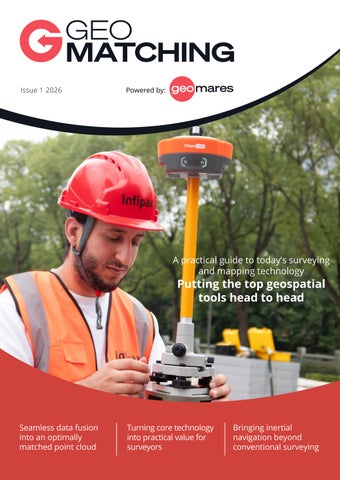
Cover story As construction begins on a new site, reliable positioning is essential. With the Infipax Titan L80 operating as a base station, surveyors can work with confidence across large and demanding areas. Its 5W internal radio provides RTK coverage of up to 20km, while a battery life of up to 44 hours keeps operations running. Discover Infipax and its next-generation positioning technology with full ISO 9001 certification at Intergeo, booth G029. (Image courtesy: Infipax)
Editorial
New technology, new possibilities New technology brings new opportunities and possibilities. While AI and ML have been integrated into a lot of hardware and software, many other innovations – both large and small – are also making a meaningful impact on the industry. For instance, Gaussian splatting has been integrated into many laser scanning systems, an increasing number of GNSS receivers now include anti-jamming/ anti-spoofing features, and tilt compensation is included in most systems, to name but a few examples. For this Intergeo Product Guide powered by Geo-matching, we have chosen to provide overviews of the following five surveying and mapping product categories: GNSS receivers, total stations, terrestrial laser scanners, mobile mapping systems, and handheld laser scanners. The ever-growing category of handheld laser scanners is a notable addition this year. These systems are simplifying surveying in hard-to-reach spaces and GNSSrestricted areas. To make it easier for you to see and compare important differences, we list the most important specifications and features for 86 products. We have also made mini-guides per product group, providing a concise summary of key trends and developments. For a more comprehensive overview of surveying equipment, visit www.geo-matching.com. The platform currently features more than 5,000 products from 1,100 manufacturers. On the Geo-matching platform (and also on the GIM International and Hydro International websites), you can also find AskGEOrge. This multilingual AI chat tool answers questions related to geospatial products and applications, providing direct
access to suitable technologies and use cases. AskGEOrge has already helped many geoprofessionals in our global audience find a suitable solution for their next project – whatever that may be! So we encourage you to try it for yourself, and let us know what you think.
Needless to say, choosing the right product is not only a matter of comparing specifications and conducting product research. That’s why we invited five industryleading manufacturers – RIEGL, CHCNAV, OXTS, Gexcel and Laser Tech – to share their vision on the industry and explain how their equipment is shaping the toolkit of tomorrow’s surveying professionals. Their contributions cover a wide variety of topics, such as seamless data fusion in the current geospatial workflow, how to manage the current data explosion while keeping autonomy and decision speed, increasing efficiency with new measurement techniques, and how to enable better connected workflows from field to office overall. There is no one-size-fits-all solution for every project, and no single manufacturer can meet the entire geospatial ecosystem’s needs. Amidst all the variety in the industry, Intergeo is a perfect opportunity to experience first-hand how the various technologies are moving forward, and to discover which new solutions and continuous improvements can best support your work as a geospatial professional. In between meeting fellow professionals and industry partners at Intergeo, don’t forget to visit Geo-matching.com, and our partner publication GIM International, for updates on the latest trends, developments, product innovations and user stories at stand B5L012. Enjoy reading this product guide – and enjoy Intergeo! Peter Tapken head of content, Geo-matching.com
Issue 1 2026
3
Translating core technology capabilities into practical value for modern surveyors By building and owning multiple technology layers, from GNSS and inertial navigation to Lidar, perception and software capabilities, CHC Navigation makes demanding geospatial work easier, safer and more productive. Here, founder and CEO George Zhao reflects on the company’s drive to ensure that advanced positioning and spatial intelligence become dependable everyday tools for surveyors, not capabilities reserved for a limited number of specialized projects.
4
How is your company contributing to providing the right equipment for the surveyor’s and geomatics engineer’s toolkit? The modern surveyor’s toolkit is becoming a connected system rather than a collection of isolated instruments. At CHC Navigation, we design each element around the task, from positioning and field capture to processing and delivery. The CHCNAV ViLi i100 combines GNSS, visual positioning and Lidar to maintain productivity when satellite visibility
is limited, while the RS7 brings professional handheld reality capture to complex indoor and outdoor environments. These instruments are supported by CHCNAV PointX positioning infrastructure and a software ecosystem that moves data into quality control, modelling and deliverable generation with fewer conversions. Our objective is to help professionals change tools less often, verify data earlier, reduce site revisits and produce survey-grade outputs faster.
A surveyor using the CHCNAV RS10 handheld SLAM laser scanner for efficient 3D reality capture and mapping on a construction site.
Which aspect of your company’s contribution to the geospatial sector – and adjacent fields – are you most proud of? I am most proud of the long-term decision to build our own core technology capabilities and translate them into practical value for customers. CHC Navigation has invested across GNSS positioning engines and antennas, inertial navigation, Lidar, SLAM, perception algorithms, correction services and professional software. Owning these layers gives us greater control over performance, integration and product continuity, but technology ownership is not the objective by itself. It must make demanding work easier, safer and more productive. Today, more than 2,200 CHC Navigation employees support customers and partners in over 140 countries across surveying, construction, hydrography, monitoring, agriculture and autonomy. What matters most to me is that advanced positioning and spatial intelligence are becoming dependable everyday tools, not capabilities reserved for a limited number of specialized projects.
Issue 1 2026
A surveyor using the CHCNAV ViLi i100 VisualLidar RTK for high-precision data collection in a complex urban environment. There is growing demand for data to be not just accessible, but directly editable and processable in the field. How far does your solution go in enabling that kind of edge processing? Edge processing should support decisions that cannot wait, while heavier computation should run where it is most effective. On CHCNAV field instruments and controllers, sensor fusion, georeferencing, point-cloud visualization, coverage checks and calculations can occur during acquisition. This allows operators to identify gaps, verify quality and correct the survey before leaving the site. At the edge, teams can extract points, calculate volumes, register datasets and prepare outputs. Larger tasks, including AI-assisted classification, terrain modelling, photogrammetry and 3D reconstruction, then
move to processing environments such as CoProcess and CoMeta. We do not believe every processing task should be forced onto the instrument. The objective is to place each function where it preserves data integrity and shortens the path from capture to deliverable. The sale is only the beginning. What does your support model look like over the lifetime of the product, and how do you handle it when things go wrong in the field? For professional users, uptime and support are part of product performance. Our model begins before deployment, with application assessment, configuration, installation guidance and operator training. It continues through local partners, regional specialists, online resources, software and firmware updates, and direct escalation to headquarters when engineering intervention is required. When an issue occurs in the field, the first response should come from people who understand the customer’s language, environment and workflow. Regional teams then address complex application questions, while product and engineering teams support root-cause analysis when necessary. This structure combines local proximity with global technical depth. The goal is to restore operations quickly and feed field experience back into product development and future training. Where do you see the biggest unmet need in the geospatial workflow right now, and how are you planning to address it? The biggest unmet need is no longer the ability to capture more data. It is the ability to convert multi-source data into trusted, interoperable
About the author George Zhao is the founder and CEO of CHC Navigation. With more than 30 years of experience in positioning and geospatial technology, he has guided the company’s development of proprietary GNSS, inertial, Lidar, perception and software capabilities, expanding CHC Navigation into a technology provider serving customers in over 140 countries.
and decision-ready deliverables without unnecessary handoffs. Users still lose time moving between separate hardware, software and file formats, while point clouds and imagery grow in scale. At CHC Navigation, we are addressing this through an integrated workflow that connects capture, positioning, processing, analysis and delivery. PointX provides a resilient positioning foundation, our sensors collect complementary data, and platforms such as CoCloud support automated processing and collaboration. AI will play an important role in classification, feature extraction and quality checks, but professional validation remains essential. Our direction is to capture once, validate early and make spatial data reusable throughout the asset lifecycle.
Capture Reality. Deliver 3D Results. RS10 & RS7 Handheld 3D Laser Scanners + GNSS RTK Visit CHCNAV at 2026 INTERGEO Hall C, Booth D149
www.chcnav.com | Your Trusted Geospatial Partner
Issue 1 2026
5
GNSS Receivers Company
Alpha GEO
Archimedes Innovation
Archimedes Innovation
Bad Elf, LLC
Title
Matrix X
AR15
AL16
Flex Mini GNSS
Height [mm]
90
72
72
-
Depth [mm]
128
72
72
-
Width [mm]
128
139
139
-
Total Weight [kg]
1
0,89
0,918
0,143
Year of last update
2026
2025
2025
-
Year of initial introduction
2026
2025
2025
2023
No. channels
1408
1408
1408
135
Max. simultaneous tracked channels
1408
1408
1408
135
Tracked satellite signals
GPS\GLONASS\BDS\ GALILEO\QZSS\ NavIC(IRNSS)\SBAS
GPS: L1C/A, L1C, L2C, L2P(Y), L5; BDS: B1I, B2I, B3I, B1C, B2a, B2b; Galileo: E1, E5a, E5b, E6; GLONASS: G1, G2, G3; QZSS: L1C/A, L1C, L2C, L5, L6; NavIC: L5; SBAS: L1C/A
GPS: L1C/A, L1C, L2C, L2P(Y), L5; BDS: B1I, B2I, B3I, B1C, B2a, B2b; Galileo: E1, E5a, E5b, E6; GLONASS: G1, G2,G3; QZSS: L1C/A, L1C, L2C, L5, L6; NavIC: L5; SBAS: L1C/A
GPS L1 C/A, L5; GLONASS L1; Galileo E1, E5a; BeiDou B1I, B2a; QZSS L1; SBAS: WAAS, EGNOS, MSAS
Reacqisition time [s]
<1s
1
1
-
Augmentation options
Single base, VRS, PPP
Single base, VRS, PPP
Single base, VRS, PPP
-
code: DGNSS/RTC (constant part) [m]
-
0,25
0,25
-
code: DGNSS/RTC (variable part) [ppm]
-
1
1
-
Horizontal uncertainty (contstant part) [m]
0,25
0,008
0,008
10
Horizontal uncertainty (variable part) [ppm]
1
1
1
1
Vertical uncertainty (constant part) {m}
0,25
0,015
0,015
-
Vertical uncertainty (variable part) {ppm}
1
1
1
-
Operating time with standard battery [hr]
15
16
16
24
Charge time [h]
5
3
3
4
Wireless
Cellular (4G/LTE), UHF Radio, Bluetooth, Wi-Fi, NFC
Cellular (4G/LTE), UHF Radio, Bluetooth, Wi-Fi, NFC, eSIM
Cellular (4G/LTE), UHF Radio, Bluetooth, Wi-Fi, NFC, eSIM
Bluetooth
Wired
USB-C, Serial
USB-C, Serial
USB-C, Serial
USB-C
IMU/tilt compensation
Y
Y
Y
-
Max. tilt angle {°}
120
60
60
-
Anti-jamming
Y
N
N
-
Anti-spoofing
Y
N
N
-
General
Performance
Uncertainty
Power
Communication
IMU/Tilt Compensation
Anti-jamming/anti-spoofing
6
Issue 1 2026
Bynav Technology
CHC Navigation
CHC Navigation
ComNav Technology
Portable RTK Pole
CHCNAV i85
ViLi i100
Mercury Laser RTK
159
86
-
171
45
134
-
76
50
134
-
81
0,24
0,8
1,39
0,5
2026
2026
-
-
-
-
-
2026
672
1892
1892
1590
672
1892
1892
1590
GPS (L1C/A, L2C, L5); Galileo (E1‑B/C, E5a, E6); BeiDou (B1I, B1C, B2a, B3I); QZSS (L1C/A, L1C/B, L2C, L5); NavIC (L1‑SPS, L5‑SPS); SBAS
GPS: L1C/A, L2C, L2P(Y), L5 GLONASS: L1, L2, L3* Galileo:E1, E5a, E5b, E6* BeiDou: B1I, B2I, B3I, B1C, B2a, B2b* QZSS: L1C/A, L1C, L2C, L5
GPS: L1C/A, L1C, L2C, L2P(Y), L5 GLONASS: G1,G2,G3 Galileo: E1, E5a, E5b, E6* BeiDou: B1I, B2I, B3I, B1C, B2a, B2b QZSS: L1C/A, L1C, L2C, L5 NavIC/ IRNSS: L5* SBAS: L1C/A*
GPS: L1C/A, L1C, L2P, L2C, L5; BDS: B1I, B2I, B3I, B1C, B2a, B2b; GLONASS: G1, G2, G3; Galileo: E1, E5a, E5b, E6c, E5 AltBOC; QZSS: L1C/A, L2C, L5, L1C; IRNSS: L5; SBAS: L1C/A
2
<1
1
≤1
Single base, VRS, PPP
Single base, PPP
PPP
PPP, VRS
0,01
0,4
0,4
0,008
1
-
1
1
0,06
0,008
0,008
0,0025
1
1
1
1
0,01
0,015
0,015
0,005
1
1
1
0,5
15
20
22
15
3
4,8
5
-
Cellular (4G/LTE), Bluetooth, Wi-Fi, UHF Radio
UHF Radio, Bluetooth, Wi-Fi, NFC
UHF Radio, Bluetooth, Wi-Fi
Cellular (4G/LTE), Bluetooth, Wi-Fi
USB-C
USB-C
USB-C
USB-C
Y
Y
Y
Y
60
60
60
120
Y
-
-
-
Y
-
-
-
Issue 1 2026
7
Company+A1:C2
Eos Positioning Systems
eSurvey
FJDynamics
GreenValley International
Title
Skadi Gold RTK GNSS Receiver
eRTK80
FJD Trion V100F
LiBase2
Height [mm]
142
78
120
75,5
Depth [mm]
95
159
130
134
Width [mm]
60
159
215
134
Total Weight [kg]
935
< 1.1
1,75
0,85
Year of last update
2026
-
2026
-
Year of initial introduction
2024
-
2026
2025
No. channels
800
1408
1408
1408
Max. simultaneous tracked channels
800
1408
-
1408
Tracked satellite signals
GPS: L1CA, L1P, L1C, L2P, L2C, L5. GLONASS: G1, G2, G3, P1, P2. Galileo: E1BC, E5a, E5b, E6BC, ALTBOC. BeiDou: B1i, B2i, B3i, B2A, B2B, ACEBOC. QZSS: L1CA, L1C, L2C, L5, LEX. IRNSS: L5
GPS, BDS, GLONASS, Galileo, QZSS, NavIC, SBAS, L-Band
GPS: L1 C/A, L1C, L2C, L2P, L5; GLONASS: L1, L2, L3; BeiDou: B1I, B2I, B3I, B1C, B2a, B2b; Galileo: E1, E5a, E5b, E6; QZSS: L1, L2C, L5, L6*; IRNSS: L5*; SBAS: L1 C/A
GPS, GLONASS, BEIDOU, GALILEO, QZSS, IRNSS
Reacqisition time [s]
<1
-
<1s
<10s
Augmentation options
Single base, VRS, PPP
PPP
PPP
Single base, VRS, PPP
code: DGNSS/RTC (constant part) [m]
0,01
0.4
0,4
0.4m
code: DGNSS/RTC (variable part) [ppm]
1
-
-
1
Horizontal uncertainty (contstant part) [m]
0,01
-
0,4
0,008
Horizontal uncertainty (variable part) [ppm]
1
-
1
1
Vertical uncertainty (constant part) {m}
0,02
-
0,8
0,015
Vertical uncertainty (variable part) {ppm}
1
-
1
1
Operating time with standard battery [hr]
9
10
5
16
Charge time [h]
2,5
-
3,5
-
Wireless
Bluetooth
Cellular (4G/LTE), UHF Radio, Bluetooth, Wi-Fi
Cellular (4G/LTE), UHF Radio, Bluetooth, Wi-Fi, NFC, LoRa
Cellular (4G/LTE), UHF Radio, Bluetooth, Wi-Fi
Wired
USB-C, Serial
USB-C
USB-C
USB-C
IMU/tilt compensation
Y
Y
Y
Y
Max. tilt angle {°}
90
60
60
60
Anti-jamming
N
-
Y
Y
Anti-spoofing
N
-
Y
-
General
Performance
Uncertainty
Power
Communication
IMU/Tilt Compensation
Anti-jamming/anti-spoofing
8
Issue 1 2026
Hi-Target
Infipax
INTEC SURVEYING
JAVAD GNSS
Juniper Systems
V600L Laser RTK
Altus M8
Magic L
PulserOne
Spire
71,99
78
109
108
143
-
139
132
144
60
130,97
139
132
144
78
0,8
1
0,85
1,1
0,33
-
-
2026
2026
2026
-
-
2026
2025
2026
1408
1408
1408
874
672
1408
-
1408
874
672
BDS/GPS/GLONASS/GALILEO/ QZSS/NavIC/SBAS/PPP
BDS: B1I, B2I, B3I, B2a, B2b; GPS: L1C/A, L1C, L2P(Y), L2C, L5; GLONASS: G1, G2, G3; GALILEO: E1, E5a, E5b, E6; QZSS: L1, L2, L5, L6; SBAS: L1C/A; PPP: B2b-PPP, L6HAS; L-BAND: Global Land
GPS:L1C/A/L2P(Y)/L2C/ L5, GLONASS:L1/L2, BDS:B1I/B2I/B3I/B1C/ B2a/B2b, Galileo:E1/ E5a/E5b/E6, QZSS:L1/ L2/L5/L6,SBAS:L1
GPS, GLONASS, Galileo, BeiDou, QZSS, SBAS, NavIC, L-Band
L1CA, L2C, L5, G1, G2, B1I, B1C, B2a, B3I, E1BC, E5a, E6, QZSS, SPS-L5
<2
-
<5s
<1
Cold Start 25 sec, Warm Start <10 sec, Hot Start 2 sec
Single base, VRS, PPP
PPP
PPP, Single base
PPP
VRS, PPP
0,25
0.4
0,5
-
0,6
1
-
10
-
1
0,008
8
0,008
0,008
0,006
1
1
1
1
1
0,015
15
0,015
0,015
0,01
1
1
1
1
1
16
20
18
7,5
20
-
3,5
4
-
4
Cellular (4G/LTE), UHF Radio, Bluetooth, Wi-Fi, NFC, LoRa
Cellular (4G/LTE), UHF Radio, Bluetooth, Wi-Fi
UHF Radio, Wi-Fi, Cellular (4G/LTE), NFC, Bluetooth
Cellular (4G/LTE), UHF Radio, Bluetooth, Wi-Fi, eSIM
Bluetooth
USB-C
USB-C, Serial
USB-C
USB-C
USB-C
Y
Y
Y
Y
Y
60
120
120
30
90
-
-
Y
Y
Y
-
-
Y
Y
Y
Issue 1 2026
9
Company+A1:C2
NovAtel
SatLab
SingularXYZ
Sokkia
Title
OEM7700
SL8
Horus
GRX5
Height [mm]
45,7
72
72
97
Depth [mm]
7,97
-
133
139
Width [mm]
71,1
131
133
139
Total Weight [kg]
0,031
0,73
0,72
0,995
Year of last update
2022
-
-
2026
Year of initial introduction
2016
2025
2025
2025
No. channels
-
1408
1408
448
Max. simultaneous tracked channels
-
1408
1408
448
Tracked satellite signals
GPS L1 C/A, L1C, L2C, L2P, L5, GLONASS2 L1 C/A, L2 C/A, L2P, L3, L5, Galileo3 E1, E5 AltBOC, E5a, E5b, E6, BeiDou B1I, B1C, B2I, B2a, B2b, B3I, QZSS L1 C/A, L1 C/B, L1C, L1S, L2C, L5, L6, NavIC L5, SBAS L1, L5, L-Band
GPS: L1C/A, L1C, L2P(Y), L2C, L5 BDS: B1I, B2I, B3I, B1C, B2a, B2b GLONASS: L1, L2, L3 Galileo: E1, E5a, E5b, E6 QZSS: L1, L2, L5, L6* NavIC: L5 SBAS: L1, L2, L5 PPP: B2b-PPP, Galileo E6-HAS
BDS: B1I, B2I, B3I, B1C, B2a, B2b GPS: L1C/A, L1C, L2C, L2P (Y), L5 GLONASS: G1, G2, G3 Galileo: E1, E5a, E5b, E6 QZSS: L1C/A, L1C, L2C, L5
GPS: L1 C/A, L1P, L2P, L2C, L5 GLONASS: L1 C/A, L2P, L2C/A, L3 Galileo: E1, E5a, E5b, E5 AltBOC, E6 BeiDou: B1, B1C, B2, B2a, B2b, B3 IRNSS (NavIC): L5 SBAS: L1, L5 QZSS: L1C/A, L1 C/B, L2C, L5
Reacqisition time [s]
<0.5s
10
1
1
Augmentation options
PPP
Single base ,VRS, PPP
Single base, PPP, VRS
Single base, VRS, PPP
code: DGNSS/RTC (constant part) [m]
1,2
0,25
code: DGNSS/RTC (variable part) [ppm]
-
1
1
General
Performance
Uncertainty
Horizontal uncertainty (contstant part) [m]
0,25
-
0,008
-
Horizontal uncertainty (variable part) [ppm]
0,01
1
1
-
Vertical uncertainty (constant part) {m}
-
3,5
0,015
-
Vertical uncertainty (variable part) {ppm}
-
0,4
1
-
Operating time with standard battery [hr]
-
16
12
15
Charge time [h]
-
-
3,5
2,5
Wireless
-
UHF Radio, Bluetooth, Wi-Fi, NFC, LoRa
UHF Radio, Bluetooth, Wi-Fi, NFC
Cellular (4G/LTE), UHF Radio, Bluetooth, Wi-Fi
Wired
USB-C, Serial
USB-C
USB-C
USB-C
IMU/tilt compensation
-
Y
Y
Y
Max. tilt angle {°}
-
60
60
60
Anti-jamming
Y
-
N
Y
Anti-spoofing
Y
-
N
Y
Power
Communication
IMU/Tilt Compensation
Anti-jamming/anti-spoofing
10
Issue 1 2026
Stonex
TechnoGIS
Topcon Positioning
Trimble
Unicore Communications
S1000 GNSS Receiver
TGS GNSS RTK
HiPer XR
R980
UM982C
68
130
97
-
21
156
130
139
-
2,6
156
85
139
-
16
0,87
0,85
0,995
1,13
0,00182
-
2025
2026
-
2026
-
2024
2025
2024
-
1408
1408
448
672
1408
1408
1408
448
672
1408
GPS: L1 C/A, L2P, L2C, L5; GLONASS: L1, L2, L3; BEIDOU: B1I, B2I, B3I, B1C, B2a, B2b; GALILEO: E1, E5a, E5b, E6; QZSS: L1, L2, L5, L6; IRNSS: L5; SBAS
GPS, BeiDou(BDS), GLONASS, Galileo, QZSS, SBAS, NavIC/IRNSS, L-Band, GPS : L1C/A, L1C, L2P(Y), L2C, L6, BeiDou (BDS) : B1I, B2I, B3I, B1C, B2a, B2b, GLONASS : L1, L2, L3, Galileo : E1, E5a, E5b, E6, SBAS : L1, L5, NavIC/IRNSS : L1, L5, L-band : B2b PPP / HAS*
GPS: L1 C/A, L1P, L2P, L2C, L5 GLONASS: L1 C/A, L2P, L2C/A, L3 Galileo: E1, E5a, E5b, E5 AltBOC, E6 BeiDou: B1, B1C, B2, B2a, B2b, B3 IRNSS (NavIC): L5 SBAS: L1, L5 QZSS: L1C/A, L1 C/B, L2C, L5
GPS (L1C, L1C/A, L2C, L2E, L5), GLONASS (L1C/A, L1P, L2C/A, L2P, L3), BeiDou (B1, B1C, B2, B2A, B2B, B3), Galileo (E1, E5A, E5B, E5 AltBOC, E6), QZSS (L1C/A, L1S, L1C, L2C, L5, L6), NavIC (L5), SBAS (L1C/A, L5)
BDS B1I, B3I, B1C, B2a, B2b GPS L1C/A, L2P(Y)/ L2C, L5 GLONASS G1, G2 Galileo E1, E5a, E5b, E6 QZSS L1C/A, L1C/B, L2C, L5, L6 L-Band
<1
<1s
1
1
<1S
-
Single base, VRS, PPP
Single base, VRS, PPP
Yes
Single base, VRS, PPP
-
0,8
0,25
0,25
0,4
-
1
1
1
1
0,005
0,0025
-
0,008
0,008
0,5
0,5
-
-
1
0,01
0,005
-
-
0,015
0,5
0,5
-
-
1
12
30
15
6,5
-
4
2
2,5
-
-
Cellular (4G/LTE), UHF Radio, Bluetooth, Wi-Fi, LoRa
UHF Radio, NFC, Bluetooth
Cellular (4G/LTE), UHF Radio, Bluetooth, Wi-Fi
Cellular (4G/LTE), UHF Radio, Bluetooth, Wi-Fi
-
-
USB-C
USB-C
USB-C. Serial
-
Y
Y
Y
-
-
60
60
60
-
-
-
-
Y
-
Y
-
-
Y
-
Y
Issue 1 2026
11
GNSS receivers The specification table on the following pages reveals a pattern: the GNSS receiver market isn’t being reshaped by one single breakthrough, but by everything getting steadily better at the same time. And the most consequential shift is happening off the spec sheet. Multi-constellation is the baseline, not the premium option A decade ago, simultaneously tracking GPS, GLONASS, Galileo and BeiDou was a selling point. Today, it’s an entry-level requirement. Nearly every full receiver listed here – from CHC Navigation’s i85 to Archimedes Innovation’s AL16 – tracks all four global constellations plus QZSS, NavIC and SBAS. Channel counts keep climbing too, with 1,408 now a common headline figure among brands ranging from Archimedes Innovation and SatLab to SingularXYZ and Stonex. Incidentally, a receiver only needs enough to track the roughly 70 satellites visible across all constellations at once. Beyond a few hundred channels, the gain is mostly marketing. From accuracy to flexibility Horizontal uncertainty figures clustering around 8mm constant part and 1ppm variable part may sound like a recent achievement, but that precision has been roughly the industry norm for about 20 years, improving only marginally each generation. Horizontal accuracy, the figure most commonly advertised, also matters less for this receiver class than vertical accuracy – harder to achieve, more relevant to survey and construction work, and rarely given equal billing. What has genuinely moved is the flexibility around that baseline: sub-second reacquisition, and single base, VRS and PPP correction all supported in the same unit. There are more variations in PPP support itself than initially apparent. Most receivers here lean on Galileo’s HAS service, solid horizontally but weaker vertically. Meanwhile, proprietary PPP from brands like JAVAD, Topcon and Trimble tends to hold up more consistently across both axes.
12
Issue 1 2026
What today’s GNSS receivers reveal Tilt compensation helps, but it isn’t free IMU-assisted tilt compensation now is near-universal, letting surveyors skip the bubble-centring step and reach points previously awkward to access directly. Advertised maximum tilt angles mostly sit in the 60-90° band. A handful of options listed here push past that, though anything much above 90° edges toward physically implausible and more likely reflects a data-entry quirk than a real capability. Remember, the correction isn’t free. Tilt-compensated measurements carry their own added uncertainty – a small accuracy cost easy to overlook when focusing on convenience. Security is firmware territory, not a fixed line Anti-jamming/anti-spoofing protection is far from standard, confirmed for just under half the receivers listed here – including established brands like JAVAD, Sokkia, Topcon and Trimble, alongside entrants such as FJDynamics and Unicore. But this is one of the fastest-moving specs in this category. Firmware updates mean realworld capability can shift ahead of what is documented, so this information should be viewed as a current snapshot rather than being set in stone. The real shift is commercial, not technical None of the above amounts to a single breakthrough. Constellation coverage, accuracy and tilt compensation have converged incrementall; what is now considered an ‘ordinary’ receiver would have been regarded as exceptional a few product cycles ago. Prices are changing even faster, with entry points drifting downward – especially among newer manufacturers. Longer-standing brands have generally held their prices, often paired with more extensive local service and support – a benefit buyers increasingly weigh up alongside the spec sheet itself.
Handheld laser scanners
The state of handheld laser scanning Handheld laser scanners capture detailed 3D data of objects and environments on the move, without the fixed setup a tripod-mounted instrument requires. Today’s systems can continuously combine observations of the object or environment from multiple viewpoints. Increasingly, they also let the operator check the developing dataset live on the device rather than in the office afterwards. SLAM is no longer optional All but one system in this overview runs on simultaneous localization and mapping (SLAM) rather than relying on a conventional GNSS/RTK workflow alone. Elsewhere, the real question has shifted from ‘Does it have SLAM?’ to ‘How well does it hold up in long sessions, repetitive corridors or low light conditions?’. Hybrid positioning is spreading Over half of this year’s scanners – three in five – now pair SLAM with RTK or PPK correction. The devices can switch between GNSS-referenced positioning outdoors and SLAM-based tracking indoors without external ground control points, merging two separate workflows into one continuous session. Colour and mesh as default outputs Around two-thirds of the scanners here carry an integrated 360° camera. Beyond adding colour to a point cloud, camera imagery can contribute additional 3D information through photogrammetry and complement the high-accuracy geometry captured by the laser. Dual systems fuse image-based reconstruction with laser measurements rather than presenting a single laser viewpoint, delivering a more complete ‘one-scan’ result. Automatic mesh generation has advanced too; most systems listed here produce a usable mesh from the captured data, reducing the amount of separate modelling needed before the result can be used in CAD or BIM workflows.
Gaussian splatting has arrived Close to two-thirds of these systems already support 3D Gaussian splatting, a rendering technique that can produce markedly more photorealistic-looking reconstructions than a traditional mesh. That visual realism should not be confused with measurement accuracy. Splatting is an interpolation and rendering method, while accuracy depends on the underlying capture, positioning and processing workflow. Live, on-device visualization is nearly universal too, though that mostly means watching the point cloud build in real time to spot coverage gaps. Typically, the captured data is still processed into a finished mesh or splat after the fact, not in the field. Persistent tradeoff between precision and weight When it comes to accuracy, the specifications are not necessarily directly comparable. Manufacturers may quote different metrics – including relative (point-to-point) and absolute (georeferenced) accuracy – and the underlying test conditions can differ. Therefore, an unusually impressive figure may reflect the way the specification is defined as much as a fundamental performance advantage. Weight is easier to compare. The lightest units come in at around 1kg, less than half that of the bulkiest, more fully equipped systems (close to 3.5kg). The variation stems from different design priorities: from fast, portable capture, to systems carrying more sensors and processing hardware.
In GIM International’s most recent industry survey, handheld scanners were mentioned unusually often as planned purchases, with the devices valued for their versatility in capturing multiple scenarios. The same survey revealed the pragmatism driving that popularity. One respondent admitted that SLAM’s near-universal adoption has pushed prices down to the point where more traditional, higher-accuracy methods struggle to compete on cost alone. The specifications show that handheld laser scanning has moved past proving itself and into the next phase. SLAM is well established, and hybrid positioning is spreading fast. Not only new capabilities but also falling prices are pulling in less experienced users. Whereas colour fidelity, output format and the weight-versus-precision balance were last year’s battlegrounds, trust in the data itself may be next year’s.
Issue 1 2026
13
Handheld Laser Scanners Company
Bad Elf, LLC
CHC Navigation
CHC Navigation
Title
Bad Elf and Pix4D Scanning Kit
RS7
RS10
Year of introduction
-
2025
2024
Year of last update
-
2026
2026
Total Weight [kg]
-
1,2
1.7kg (including RTK and battery)
Hardware Material
Polycarbonate (GNSS receiver component: Bad Elf Flex Mini Extreme)
-
-
Certification and calibration
-
IP64 (IEC 60529); Class 1 Eye Safe laser
IP64 (IEC 60529); Class 1 Eye Safe laser
Min. Range [mm]
-
-
500
Max. Range [mm]
-
40,000
300,000
Max. vertical field of view [deg]
-
189
40,3
Max. horizontal field of view [deg]
-
360
360
3D measurement accuracy [mm]
-
<30mm absolute (H/V RMS); <10mm relative
-
Data aquisition speed (points p/second)
-
Single Return: 576 000 pts/sec; Dual Return: 1,152,000 pts/sec
Single Return: 640 000 pts/sec; Dual Return: 1 280 000 pts/sec; Triple Return: 1,920,000 pts/sec
Number of cameras
-
2
3
Camera resolution (MP)
-
48
15
360 degrees camera
-
-
N
Sensor chip
-
-
-
SLAM technology
-
Y
Y
SLAM algorithm type
-
LiDAR+IMU (LIO)
Hybrid
SLAM accuracy {mm}
-
-
30
Positioning modes
GNSS,RTK< PPK
SLAM, GNSS
SLAM, RTK< PPK, GNSS
GNSS RTK integrated
Y
-
Y
Operating temperature: min. [°C]
-
-20
-20
Operating temperature: max. [°C]
-
50
50
Humidity range [%]
-
-
80%, Nn-condensing
Battery type
-
Integrated battery in handle, 47.5 Wh
Lithium battery, supports hot-swapping and portable charger
Scan time per battery [h]
-
2,5
1
Mesh as output
Y
Y
-
Gaussian Splatting Output
-
Y
-
Real time visualization during scanning
Y
Y
Y
Other Formats
Point cloud, GCPs (Ground Control Points) and marks
Colorized point clouds, 3D Gaussian Splatting (3DGS)
-
General
Scanning Characteristics
Camera specifications
SLAM technology
Positioning modes (SLAM/RTK/PPK)
Operation Characteristics
Power
Functionality
14
Issue 1 2026
ComNav TechNlogy
Emesent
eSurvey
Exyn TechNlogies
LS600
GX1
eXplore 70
Nexys
2025
2026
-
2024
-
2026
-
2026
2,3
3,5
1,6
3,1
Industrial-grade aluminum
Aluminium housing
-
-
-
Y
FCC, CE
IP67
500
500
-
-
300,000
300,000
70,000
100,000
270
284
59
-
360
360
360
360
Absolute: 30mm (RMSE); Real-time relative: 20mm; Processed relative: 10 mm; Point cloud thickness: ≤5mm
10
Relative < 20, Absolute < 30
±10mm (1 sigma)
640,000
1,920,000
200,000
1,280,000
2
4
4
2
48
20
-
3,2
Y
Y
Y
Y
-
NA
-
FLIR Blackfly
Y
Y
Y
Y
Hybrid
LiDAR+IMU (LIO)
Hybrid
-
-
-
-
10
SLAM, RTK< PPK, GNSS
SLAM, RTK< PPK, GNSS
SLAM, RTK< PPK, GNSS
SLAM, RTK< PPK
Y
Y
Y
-
-20
-10
-20
-20
50
45
55
45
-
Up to 99%
-
Li-ion battery
54Wh 10.8V Smart Li-Ion Battery (removable)
Built-in: 14.4 V, 3400 mAh; optional hot-swappable Handle battery: 14.4 V, 3400 mAh
V-Mount Li-Ion
1,5
1
-
2
-
Y
-
-
-
Y
-
-
Y
Y
-
Y
Point cloud (.las), Images (.jpg)
-
-
LAS, PLY, XYZ, E57
Issue 1 2026
15
Providing state-of-the-art solutions engineered to solve true ‘survey nightmares’ With an integrated ecosystem bridging hardware, desktop software and automated monitoring, Gexcel supports fast and accurate 3D reality capture, seamless data handling and a singleproject approach to deliver high-density meshes and other exports. Here, Giorgia Rossi, international sales manager at Gexcel, explains how the company offers decisive benefits for users, ranging from operational advantages to step-by-step support. She also discusses how the industry can manage the data explosion without sacrificing field autonomy or decision speed. How is your company contributing to providing the right equipment for the surveyor’s and geomatics engineer’s toolkit? Gexcel equips geomatics engineers and surveyors with an integrated ecosystem bridging hardware, desktop software and automated 3D monitoring. This includes HERON wearable systems for SLAM portable mapping, enabling ultra-fast, highly accurate 3D reality capture across challenging underground, outdoor and complex architectural environments. Our desktop post-processing software breaks processing limits, allowing seamless data handling anywhere. Meanwhile, our multi-sensor 3D software called Reconstructor processes and merges point clouds from diverse terrestrial laser scanners, mobile mapping devices and drones into a single project. It integrates seamlessly with BIM and 3D mesh models,
HERON 3D mapping system.
16
Issue 1 2026
delivering high-density meshes, DTMs and direct exports to CAD and BIM platforms. Additionally, for automated 3D monitoring, our OPMMS and 3DSMS deliver continuous, targetless slope stability tracking, real-time deformation heatmaps and precise volumetric analysis for mining, quarrying and stockpiles. Which aspect of your company’s contribution to the geospatial sector – and adjacent fields – are you most proud of? Powered by our patented SLAM algorithm, HERON and Reconstructor set the industry benchmark for complex 3D data collection, point cloud processing and digital twin generation. We take tremendous pride in providing state-of-the-art solutions engineered to solve true ‘survey nightmares’, and our capability to seamlessly manage massive spatial datasets within a single project is proven across extremes. In architecture, for example, our technology was used in the landmark survey of the Doge’s Palace in Venice, managing 101 trajectories and 17km of complex walking paths. Meanwhile, in a mine, a massive subterranean survey spanned 20km (round trip) across 14 trajectories deep underground. Whether navigating delicate historic spaces or dark, challenging mine shafts, Gexcel empowers surveyors to conquer their toughest reality capture challenges with complete confidence. There is growing demand for data to be not just accessible, but directly editable and processable in the field. How far does your solution go in enabling that kind of edge processing? Managing data directly in the field provides a decisive operational advantage, which is why HERON is built to be 100% cloudindependent. Users can verify, inspect and fully post-process 3D point cloud data on site using a standard PC, without an internet connection. This enables immediate data validation and rapid generation of draft or final deliverables, even in time-critical or security-sensitive environments. For automated monitoring, OPMMS performs all processing locally on the edge. Surface displacement calculations, monitoring results and safety alerts are generated on site in real time, ensuring immediate response without relying on connectivity. At the same time, authorized remote teams can securely
About the author
HERON’s coloured 3D point cloud model. access the local database to perform advanced geotechnical analysis and review long-term surface trends from anywhere in the world. The sale is only the beginning. What does your support model look like over the lifetime of the product, and how do you handle it when things go wrong in the field? We view every sale as the start of a long-term partnership. We take exceptional care of what happens after delivery. Because our team consists of domain experts – engineers, geotechnical specialists and architects – we guide our users step by step, both in the field and in the office. We offer a comprehensive support structure ranging from hands-on training and standard email helpdesk to interactive remote sessions for data verification and complex elaboration. When challenges arise in the field, our users know they aren’t alone; they speak directly with professionals who share their exact technical background, giving them complete confidence every step of the way.
Giorgia Rossi has been working at Gexcel as manager of worldwide sales since 2008, developing and strengthening the client and reseller network while gaining extensive experience in international markets. In her work, she particularly enjoys meeting people, attending conferences, organizing sales/ technical training and interacting with professionals. Where do you see the biggest unmet need in the geospatial workflow right now, and how are you planning to address it? The geospatial industry faces a major challenge: managing the data explosion without sacrificing field autonomy or decision speed. We see the biggest gaps in three areas. First, there is a processing bottleneck. Capturing 3D data is fast, but turning large datasets into final deliverables remains slow. We address this by optimizing Reconstructor to seamlessly handle multiple sensors and multiplatform support. The second issue is cloud dependency. Many modern platforms force users into constant cloud uploads. We address this by keeping HERON 100% cloud-independent, ensuring full on-premise capability even in deep underground or remote sites. Third, there is a gap between static data and live intelligence. Whereas traditional surveys are static snapshots, with OPMMS and 3DSMS we turn standard Lidar setups into continuous, automated 3D monitoring hubs that alert teams to movement in real time.
Issue 1 2026
17
Handheld Laser Scanners Company
FARO INSIGHT
Feima Robotics
FJDynamics
Title
Orbis Premium Mobile Laser Scanner
SLAM200
FJD Trion X1
Year of introduction
2024
2024
2026
Year of last update
-
2026
2026
Total Weight [kg]
3,6
1,9
1,3
Hardware Material
Various
Ariel aluminium
Alloy
Certification and calibration
Calibration certificate included
FCC, CE,
CE, FCC, PSE, WEEE, RoHs
Min. Range [mm]
-
500
500
Max. Range [mm]
120
300,000
70,000
Max. vertical field of view [deg]
360
270
62
Max. horizontal field of view [deg]
290
360
360
3D measurement accuracy [mm]
5
Absolute accuracy: <5cm
Relative: ≤10; Absolute: 30
Data aquisition speed (points p/second)
640,000
640 kpts/s
384,000
Number of cameras
-
2
3
Camera resolution (MP)
72
12
48
360 degrees camera
Y
Y
Y
Sensor chip
-
General
Scanning Characteristics
Camera specifications
1/2.0‑inch
SLAM technology SLAM technology
Y
Y
Y
SLAM algorithm type
LiDAR-only SLAM,Visual-Inertial SLAM
Hybrid
Hybrid
SLAM accuracy {mm}
5
5
-
Positioning modes
SLAM
SLAM
SLAM
GNSS RTK integrated
N
Y
Y
Operating temperature: min. [°C]
0
-20
-20
Operating temperature: max. [°C]
40
50
50
Humidity range [%]
-
<95
90
Battery type
Li-ion
Lithium smart battery handle
DC handheld battery
Scan time per battery [h]
3
1
2,5
Mesh as output
Y
Y
Y
Gaussian Splatting Output
Y
Y
Y
Real time visualization during scanning
Y
Y
Y
Other Formats
-
las, e57
.las, .pts, e57, .ply
Positioning modes (SLAM/RTK/PPK)
Operation Characteristics
Power
Functionality
18
Issue 1 2026
Geosun Navigation
GEXCEL
GreenValley International
Hi-Target
GS-203
HERON Lite Color
LiGrip O2 Pro
LS1 PRO
2025
2019
2026
2026
2026
-
2026
-
1,7
1.7kg (handheld) + 1.1kg (over the shoulder)
1,68
1,68
Aluminum alloy
TechNpolimer, aluminum
-
-
CE and calibraton file
EU declaration of conformity
CE, PSE, FCC, and TELEC
Hi-Target standard calibration conditions (RMS)
500
500
500
-
70,000
300,000
300,000
300,000
59
360
300
280
360
360
360
360
≤20 mm @10 m,≤30 mm @0.2 m
10
Relative accuracy < 5mm; Absolute accuracy < 30mm
Relative: 10mm; Point cloud thickness: 10mm; Absolute: up to 20mm
200,000 pts/s
640,000
640,000 pts/s
640,000
3
4
3
3
12
33
48
48
Y
Y
Y
-
-
CMOS Rolling Shutter Color
1-inch CMOS × 3
-
Y
Y
Y
Y
-
LiDAR+IMU (LIO)
Hybrid
LiDAR+IMU (LIO)
10
10
5
-
-
SLAM,GNSS
SLAM, RTK< PPK
SLAM, RTK< PPK
Y
Y
Y
Y
-20
-10
-20
-20
55
35
40
55
80
Nn condensing 95% rel
-
IP54
Lithium battery
Li-ion 6700 mAh | 80.4 Wh | 12 V
-
Handle battery / UAV power
2
1,5
2
3
Y
Y
Y
Y
Y
Y
Y
Y
Y
Y
Y
Y
-
.e57, .las, .ply, export in ReCap
LAS, LiData, Imglist + JPG, LOD-OSGB, lisplat, PLY
Point cloud, mesh, architectural outputs
Issue 1 2026
19
Company
Lidaretto
OmniSLAM Co., Ltd.
SatLab
Title
H32(X) - SLAM
R8+
Cygnus 3
Year of introduction
2024
2024
2026
Year of last update
2026
2026
-
Total Weight [kg]
1,6
2,1
1.98
Hardware Material
Aluminium, plastic
Engineering plastic + aluminum alloy
-
Certification and calibration
-
CE
SatLab standard calibration conditions (RMS)
Min. Range [mm]
0
50
-
Max. Range [mm]
300
120,000
120,000
Max. vertical field of view [deg]
40
31
280
Max. horizontal field of view [deg]
360
360
360
3D measurement accuracy [mm]
20
2
Relative: 10mm; Absolute: up to 40mm
Data aquisition speed (points p/second)
-
640,000
320,000
Number of cameras
1
1
3
Camera resolution (MP)
-
21
48
360 degrees camera
Y
Y
-
Sensor chip
-
Insta360 ONE RS 1-Inch Edition
-
SLAM technology
Y
Y
Y
SLAM algorithm type
LiDAR+IMU (LIO)
LiDAR+IMU (LIO)
-
SLAM accuracy {mm}
-
2
-
Positioning modes
SLAM, GNSS, RTK< PPK
SLAM, RTK< PPK, GNSS
SLAM, RTK< PPK
GNSS RTK integrated
-
Y
Y
Operating temperature: min. [°C]
-10
-25
-20 °C
Operating temperature: max. [°C]
45
65
55
Humidity range [%]
-
-
IP54
Battery type
External
li-ion rechargeable battery
-
Scan time per battery [h]
-
1,5
3
Mesh as output
-
Y
Y
Gaussian Splatting Output
-
N
Y
Real time visualization during scanning
-
Y
N
Other Formats
-
.las, .laz, .e57
Point clouds, mesh, 3DGS, DEM, contours, sections and profiles
General
Scanning Characteristics
Camera specifications
SLAM technology
Positioning modes (SLAM/RTK/PPK)
Operation Characteristics
Power
Functionality
20
Issue 1 2026
SHARE3DCAM
SingularXYZ
SKYLANDX
Sokkia
SLAM S100
H1
MetaCam Lite
SR-S1
2025
2025
2026
2026
2026
2026
2026
2026
2,438
1,242
1,12
2,2
Aluminium alloy
-
-
Plastic, aluminum
CTA \ RoHS
Class 1 Eye Safe
-
CE, FCC, PSE, ICES, ROHS, RED calibration is done in the factory
500
40,000
50
-
300,000
140,000
70,000
120,000
40,3
63,5
65
360
360
360
360
280
Absolute Accuracy: ≤ 5cm Relative Accuracy: ≤ 1cm
1.5cm@10m; 3cm@20m; 5cm@40m
Absolute Accuracy: 5cm ; Relative Accuracy: ≤ 8mm
<30
640,000
480,000
216,000
640,000
4
3
2
5
16
13
48
12
N
Y
N
Y
IMX283
-
1/2"
-
Y
Y
Y
Y
LiDAR+IMU (LIO)
LiDAR+IMU (LIO)
Hybrid
LiDAR-only SLAM, Visual-Inertial SLAM, LiDAR+IMU (LIO), Hybrid
-
-
-
10
SLAM, GNSS, RTK< PPK
GNSS, RTK< PPK, SLAM
SLAM
SLAM, RTK< PPK
Y
Y
N
Y
-20
-10
-20
-20
50
50
55
40
90
-
95%
-
Li-ion
Li-ion
Li-ion
Li-ion
1,5
1
2,5
2
Y
Y
Y
Y
Y
Y
Y
Y
Y
Y
Y
Y
.LAS, .PLY, .PCD
PCD, LAS, E57, PLY
-
3D point clouds, meshes, paNramic images
Issue 1 2026
21
Company
Stonex
TechNGIS
Topcon Positioning
ZENiTH
Title
X200GO
GeoLiDAR SLAM Lite 1
CR-S2
POCKET 2
Year of introduction
2024
2024
2026
2026
Year of last update
-
2025
2026
2026
Total Weight [kg]
1,9
1
1,3
1,275
Hardware Material
-
Aluminium alloy
Plastic, aluminum
Aviation‑grade aluminum alloy & Engineering plastic
Certification and calibration
IEC/EN 60825-1:2014 (laser eye-safety, Class 1)
MSDS,CE,ISO
CE, FCC, PSE, ICES, ROHS, RED - calibration is done in the factory
CE self‑declaration; Factory‑pre‑calibrated, built‑in calibration file
Min. Range [mm]
500
500
-
0,1
Max. Range [mm]
300,000
7,000
70,000
70
Max. vertical field of view [deg]
360
59
52
59
Max. horizontal field of view [deg]
290
360
360
360
3D measurement accuracy [mm]
6
≤20mm @10m,≤30mm @0.2m
<30
10
Data aquisition speed (points p/second)
640,000
200,000
200,000
200,000
Number of cameras
2
2
4
3
Camera resolution (MP)
12
20
12
2
360 degrees camera
Y
N
Y
N
Sensor chip
-
-
-
Global shutter RGB sensor
SLAM technology
Y
Y
Y
Y
SLAM algorithm type
-
Hybrid
Visual-Inertial SLAM, LiDARonly SLAM, LiDAR+IMU (LIO), Hybrid
Hybrid
SLAM accuracy {mm}
Y
15
20
50
Positioning modes
SLAM, RTK< PPK, GNSS
GNSS, RTK< PPK
SLAM, RTK< PPK
SLAM, INS-only, RTK< PPK, GNSS
GNSS RTK integrated
-
Y
Y
N
Operating temperature: min. [°C]
-20
-20
-20
-10
Operating temperature: max. [°C]
50
55
40
40
Humidity range [%]
95
80
-
10-90
Battery type
li-ion
lithium battery
Li-ion
Li‑ion rechargeable battery
Scan time per battery [h]
1,2
1,5
2
2
Mesh as output
-
Y
Y
Y
Gaussian Splatting Output
-
Y
Y
Y
Real time visualization during scanning
Y
Y
Y
Y
Other Formats
-
PLY, OBJ, OSJB, LAS, TXT
3D point clouds, meshes, paNramic images
LAS, LAZ, FBX, E57, PCD, PLY, OBJ
General
Scanning Characteristics
Camera specifications
SLAM technology
Positioning modes (SLAM/RTK/PPK)
Operation Characteristics
Power
Functionality
22
Issue 1 2026
Mobile mappers
Scrutinizing modern mobile mappers Mobile mapping used to be a straightforward ‘arms race’: more points per second, longer range, higher resolution. This lineup still has plenty of that, but the more telling story is what’s built around the sensor – how a system positions itself, what platforms it rides on and how much of the workflow it handles on its own. The high end still pushes raw performance At the top of the measurement-rate scale in this overview are CHCNAV’s AU20 MMS and Geosun Navigation’s gCollector-323, both listed at up to 2,000kHz. The gCollector-323 also has the longest stated range at 1,500m, narrowly ahead of the AU20’s 1,450m. Those headline figures should not be read as accuracy specifications. Ultimately, the accuracy of the georeferenced point cloud is determined by trajectory quality, sensor calibration, control and survey conditions. SLAM is spreading, but not yet universal Mobile mappers are still mid-transition to SLAM. Six of the nine systems in this overview list SLAM among their positioning modes: ComNav’s ML300, Geosun Navigation’s gCollector-323, Emesent’s Hovermap STX, GreenValley International’s LiMobile M2 Lite, JAWESO’s Panora Pro PL and Lidaretto’s multiplatform mapping system. Vehicle systems commonly derive their trajectory from GNSS integrated with inertial sensors, with RTK or PPK used where supported. An inertial solution can bridge short GNSS outages. However, uncertainty grows with time. SLAM can provide an additional constraint in tunnels, urban canyons and other GNSS-challenged environments, provided that sufficiently stable geometry is available. Multiple deployment options Platform flexibility is another dividing line. Emesent’s Hovermap STX supports vehicle, backpack, handheld, UAV and rail
deployment, while Lidaretto’s multiplatform mapping system adds USV to that mix. CHCNAV’s AU20 MMS can be deployed on a vehicle or UAV, and Geosun’s gCollector-323 is listed for USV and rail use. In contrast, GreenValley’s LiMobile M2 Lite, Horus’s Vertex 72MP and imajing’s imajbox 360HD are vehicle-focused, while JAWESO’s Panora Pro PL supports vehicle and rail deployment. Cameras have quietly become a headline spec All nine systems in this overview are listed with 360° imaging capability. Among the stated camera specifications, JAWESO’s Panora Pro PL reaches 200MP, while several systems list 72MP. High-resolution panoramic imaging supports point-cloud colourization, asset interpretation and – where cameras are appropriately calibrated and synchronized with the trajectory – image-based measurement. Megapixel count alone, however, does not determine measurement quality. Weight: what to watch When it comes to weight, there is a broad spread. Lidaretto’s multiplatform mapping system (1.4kg) and Emesent’s Hovermap STX (1.57 kg) are light enough to carry by hand, whereas Horus’s Vertex 72MP is listed at 46.2kg and sits firmly in dedicatedvehicle territory. Manufacturers do not always quote weight on the same basis; the figure shown may describe a sensor head or payload, rather than every component required for operational installation. Taken together, this category is settling into two sub-groups: portability-first systems chasing flexibility, and performance-first systems optimized for accuracy, range and high-speed corridor productivity. The boundary is not absolute. But when comparing systems for survey work, the key factors are the accuracy and repeatability of the final georeferenced deliverable under the real-world deployment conditions.
Issue 1 2026
23
Mobile Mappers Company
CHC Navigation | CHCNAV
ComNav Technology
Geosun Navigation
Emesent
Title
CHCNAV AU20 MMS
ML300
gCollector-323
Emesent Hovermap STX
Dimensions & Environment Weight [kg]
14
25
1,57
Application
Outdoor, Airborne
Outdoor
Outdoor,Rail
Outdoor, Indoor, Underground, Rail, Airborne
Carrier platforms
Vehicle, UAV
Vehicle
USV, Rail
Vehicle, Backpack, Handheld, UAV, Rail
Brand and model
C4800, C7200
FLIR Ladybug5+ (standard camera); Ladybug6 (optional upgrade)
Geosun & FisherEye
GoPro Hero and GoPro Max
Number of cameras
6
1
4
2
Max. camera resolution {MB}
72
30
12
5,6
-
0,59
Model dependant
Y
Y
Y
Y
Brand
CHCNAV
-
PRO 360/Hesai XT M2X
Hesai
Number of laser scanners
2
2
2
1
Min. Range [m]
1,5
0,5
10
0,5
Max Range [m]
1450
300
1500
300
Wavelength [nm]
-
-
1550
905
Max. measurement rate [kHz]
2000
1280
2000
1920
Range precision (1 σ)
3
-
1
4
Absolute accuracy (1 σ):
5
0,01
3
10
Positioning modes
GNSS
SLAM,GNSS
SLAM,RTK< PPK
SLAM, RTK< PPK, GNSS
GNSS receiver: Brand and model
CHCNAV, AT312
-
Unicomm & UM982
With external RTK receivers: Emlid RS2/RS2+/RS3, Leica GS18/GS18I/GS18T, Trimble R10/R12/R12i/R980
Number of antennas
1
-
1
-
Tracked GNSS signals
GPS: L1,L2,L5; GLONASS: L1,L2; BeiDou: B1,B2,B3; Galileo: E1,E5a,E5b
GPS, BDS, GLONASS, Galileo, QZSS, SBAS
1480
-
Camera System
Sensor size [inch} 360 degrees camera Lidar Sensor
Positioning
24
Issue 1 2026
GreenValley International
Horus
imajing
JAWESO Mobile Mapping Systems
Lidaretto
LiMobile M2 Lite
Horus Vertex 72MP
imajbox 360HD
JAWESO Panora Pro PL
Multiplatform Mapping System
6
46,2
14
24
1,4
Outdoor, Underground
Outdoor
Outdoor
Outdoor ,Rail
Outdoor, Indoor, Rail, Airborne, Underground
Vehicle
Vehicle
Vehicle
Vehicle, Rail
Vehicle, Backpack, Handheld, UAV, USV, Rail
-
Ladybug 5+ of Ladybug 6
Teledyne LDB6
-
Pano 8K
4
6
6
2
1
12
72
72
200
-
-
-
12,288 x 6,144 pixels pano
-
-
Y
Y
Y
Y
Y
Hesai
Hesai
none
-
Hesai XT32/XT32M2X
2
1
-
2
1
0,05
0,5
-
-
0,5
300
300
-
120
300
905
905
-
-
905
1280
1920
-
640
-
1
0,5
-
-
0,01
5
1
-
1,5
3
SLAM,GNSS
GNSS
GNSS, RTK< PPK
SLAM,RTK< PPK, GNSS
SLAM,RTK< PPK,GNSS
-
AP+ 18/30/50
Septentrio Mosaïc X5
SBG Quanta Plus
Novatel OEM7720
1
2
1
-
2
GPS, GLONASS, Galileo, BeiDou, QZSS, SBAS
GPS (L1 C/A, L2C, L2E, L5), GLONASS (L1 C/A, L2 C/A, L3 CDMA), BeiDou (B1, B1C, B2, B2A, B36), Galileo (E1, E5A, E5B, E5AltBOC, E64), IRNSS: (L5), QZSS (L1 C/A, L1 SAIF, L1C, L2C, L5, LEX), SBAS (L1 C/A, L5), MSS L-Band (OmniSTAR, Trimble RTX)
GNSS, GLONASS, Galileo, BeiDou, QZSS, SBAS
-
GPS, GLONASS, Galileo, BeiDou
Issue 1 2026
25
Helping professionals rethink where measurement has to happen Laser Tech’s reflectorless laser measurement technology extends the reach of the surveyor’s toolkit by giving professionals another way to measure distance, inclination, height, clearance, width and azimuth. Here, Derrick Reish discusses the next evolution of field efficiency: getting more value from every field visit by capturing more information in less time, accomplishing more on site and completing more projects with the same resources. How is your company contributing to providing the right equipment for the surveyor’s and geomatics engineer’s toolkit? The geospatial professional is being asked to collect more data, faster and often in places where traditional positioning methods alone are not enough. Our role is to extend the reach of the existing toolkit. Laser Tech’s reflectorless laser measurement technology gives professionals another way to capture distance, inclination, height, clearance, width and azimuth measurements. When integrated with GIS and GNSS workflows, those measurements can help position assets that are difficult, unsafe, inaccessible or simply inefficient to occupy physically. We don’t see laser rangefinders as a replacement for GNSS or other surveying technologies. We see them as making those technologies more capable. The right tool and setup is the one that lets you collect the data you need from the position that makes the most sense. Which aspect of your company’s contribution to the geospatial sector – and adjacent fields – are you most proud of? We are proud of helping professionals rethink
TruPulse laser rangefinders let professionals capture remote measurements and position hardto-reach assets without physically occupying every point.
26
Issue 1 2026
where measurement has to happen. For decades, the assumption has often been that if you need information about an asset, you have to physically get to it. But field conditions don’t always cooperate. There may be traffic, private property, dangerous terrain, vegetation, blocked GNSS signals or simply too much ground to cover. Our technology gives professionals another option: measure the asset from where you stand. With a TruPulse rangefinder, users can capture remote measurements and incorporate that information into GIS and GNSS workflows. That idea extends well beyond traditional surveying. Professionals in utilities, forestry, telecommunications, construction, mining, public works and other sectors are all being asked to collect more detailed information in the field. We’re proud that our technology helps them collect that additional data without necessarily adding additional steps, equipment or exposure to the field environment. There is growing demand for data to be not just accessible, but directly editable and processable in the field. How far does your solution go in enabling that kind of edge processing? Our goal is to make the measurement itself part of the field-data workflow, not a separate task that has to be reconciled later. The TruPulse i-Series performs calculations directly onboard, including horizontal and vertical distance, height and missing-line measurements. The TruPulse 360i adds azimuth data, enabling 3D point-to-point calculations and remote positioning. From there, our mobile app software helps move that information into the user’s existing workflow. LaserSoft Connect integrates TruPulse measurements with ArcGIS Field Maps, allowing users to calculate remote locations and add measurement attributes to their field data. LaserSoft MapSmart provides another complete field-data collection workflow for mapping, measuring, positioning and calculating information such as stockpile volumes. The objective is simple: capture more of the data you see while you’re already in the field. The sale is only the beginning. What does your support model look like over the lifetime of the product, and how do you handle it when things go wrong in the field? Laser Tech’s professional measurement equipment has to perform outside the controlled environment of a lab. Our products are built around that reality, but supporting professionals means more than building rugged hardware. We provide field guides, manuals, training resources, software support, calibration guidance and technical assistance designed to help users get the most from their equipment
About the author
Reflectorless laser measurement provides distance, inclination, height, clearance and other measurements from a position chosen for efficiency and safety. throughout its life. The current TruPulse i-Series products also include a two-year manufacturer’s warranty. Just as importantly, we focus on helping customers understand the workflow behind the measurement. A technical problem isn’t always a hardware problem. Sometimes, the question is how to approach a difficult target, which measurement routine to use or how to incorporate the result into a GIS workflow. Our responsibility doesn’t end when the measurement tool leaves our facility. If the equipment is going into the field with you, our support goes there too. Where do you see the biggest unmet need in the geospatial workflow right now, and how are you planning to address it? One of the biggest opportunities is getting more value from every position a field professional occupies. GNSS has transformed how we capture location data, but there will always be assets that
Derrick Reish, global manager of product management at Laser Tech (LTI), has over 27 years of experience in professional measurement and mapping. He focuses on understanding customer challenges and transforming insights into innovative solutions that prioritize worker safety. LTI delivers seamless field-to-office solutions serving electric utilities, public works, forestry, construction and mining. are inaccessible, obstructed, unsafe to occupy or outside reliable signal coverage. At the same time, organizations want more than a coordinate. They want the measurements and attributes that make that coordinate useful. That’s where we see the opportunity: collect more measurements from where you stand. Our focus is on making laser measurement increasingly connected to the workflows professionals already use. TruPulse rangefinders can work with third-party GIS apps and GNSS equipment, while our software solutions like LaserSoft Connect and MapSmart bring measurement, position, calculations and field data together. The next evolution of field efficiency is about getting more from every field visit. When professionals can collect measurement data without occupying every asset, they can capture more information in less time, accomplish more on site and complete more projects with the same resources.
Issue 1 2026
27
Mobile Mappers Company
MetaSpatial Solutions
Mosaic 360 Camera Systems
NorPix, Inc
Title
Echo MobileMapper
Mosaic Meridian Mobile Mapping System with High-Resolution 360° Camera and LiDAR
Paved Surface Capture
Weight [kg]
8
9,5
5
Application
Outdoor, Underground, Rail
Outdoor, Rail
Outdoor
Carrier platforms
Vehicle, Backpack, Rail, USV
Vehicle
Vehicle
Brand and model
Sony Sensors
Mosaic X
-
Number of cameras
4
6
-
Max. camera resolution {MB}
240
12,2
50
Sensor size [inch}
Full Frame
1/1.1" (Sony IMX565)
-
360 degrees camera
N
Y
-
Brand
Hesai XT32MX
Phoenix
-
Number of laser scanners
1
32
-
Min. Range [m]
2
0,5
-
Max Range [m]
97
300
-
Wavelength [nm]
948
-
-
Max. measurement rate [kHz]
640
1200
-
Range precision (1 σ)
1
0,5
-
Absolute accuracy (1 σ):
1
2
-
Positioning modes
RTK< PPK, GNSS, INS-only
RTK< PPK
GNSS
GNSS receiver: Brand and model
-
NovAtel
-
Number of antennas
2
1
-
Tracked GNSS signals
-
GPS, GLONASS, BeiDou, Galileo
-
Dimensions & Environment
Camera System
Lidar Sensor
Positioning
28
Issue 1 2026
OmniSLAM Co., Ltd.
RIEGL
Smart Delta Systems & Solutions
Trimble, Inc.
YellowScan
Q8
VMX-3HA
SmartPano Elite
Trimble MX90
Fly&Drive
13
38,4
16
-
4,98
Outdoor
Outdoor, Underground, Maritime, Rail
Outdoor
-
Outdoor, Airborne
Vehicle
Vehicle, Rail
Vehicle
-
Vehicle, UAV, Rail
Insta360 ONE RS 1-inch edition
RIEGL cameras (5MP, 12MP, 24MP), spherical cameras up to 72MP
Ladybug 5+ (30MP) or Ladybug 6 (72MP, global shutter)
FLIR Ladybug 6 & Matrix Vision
Teledyne Ladybug 5+ in option
1
9
-
-
6
61
240
72
-
5
1
Different options
-
-
-
&
Y
Y
-
Y
Hesai
RIEGL VUX-3HA LiDAR Sensor
Compatible with Hesai and Ouster OS1-128
Trimble
Hesai
4
2
-
2
1
0,05
1
-
1,2
-
120
500
-
475
140
950
1550
-
-
905
640
6000
-
3600
20
1
2
-
-
3
0,5
3
-
-
2,5
SLAM, RTK, PPK, GNSS
RTK< PPK, GNSS, INS-only
GNSS,RTK< PPK
-
GNSS
Harxon: HX-CSX349A-0875
Trimble / Applanix
Customer-selectable: NovAtel, Applanix, Advanced Navigation or SBG GNSS/INS unit
Calian
SBG Systems Quanta Micro
1
1
1
1
1
GPS: L1/L2/L5 BDS: B1I/B2I/B3I/B1C/B2a/B2b GLONASS: G1/G2/G3 GALILEO: E1/E5a/E5b/E6 QZSS: L1/L2/L5/L6 SBAS: L1/L5 IRNSS: L5
GPS: L1 C/A, L2C, L2E, L5; GLONASS: L1 C/A, L2 C/A, L3 CDMA6; BeiDou: B1, B2, B38; Galileo7: E1, E5A, E5B, E5AltBOC, E66; IRNSS: L5; QZSS: L1 C/A, L1S, L1C, L2C, L5, LEX; SBAS: L1 C/A, L5; MSS L-Band: Trimble RTX
-
-
-
Issue 1 2026
29
Terrestrial Laser Scanners Company
EPiC LiDAR Tech
FARO INSIGHT
GreenValley International
Title
AXIM T150
FARO Focus Premium Max
LiPod P1
Height [m]
0,105
0,183
0,202
Width [m]
0,216
0,23
0,107
Depth [m]
0,168
0,103
0,247
Total Weight [kg]
3,3
4,4
5,3
Year of introduction
2026
2024
2025
Year of last update
2026
-
2026
Laser safety classification
Class I
Laser Class 1
1
Min. Range [m]
0,5
0,5
1,5
Max. Range [m]
150
400
600
Range uncertainty (constant part) [mm]
2
1
5
Range uncertainty (variable part) [ppm]
-
-
-
Beam divergence [mrad]
0,56
0,3
0,3
Max. vertical field of view [deg]
300
300
300
Max. horizontal field of view [deg]
360
360
360
Max. measurement rate [kHz]
1200
2000
120
Geo-referencing
Y
Y
Y
Onboard registration
Y
Y
Y
Automatic face blurring
N
Y
N
Integrated GNSS
Y
Y
Y
Integrated GNSS RTK
Y
N
N
Additional sensors
Environmental sensor
Dual axis compensator, height sensor, compass, accessory bay
IMU inertial navigation system; dual‑axis compensation; altitude sensor; compass
External Camera
N
Y
Y
Max. camera resolution (MP)
12
266
12,3
Simultaneous image scan
Y
Y
Y
General
Laser Ranger
Scanning Characteristics
Software Functionality
GNSS Integration
Peripherals
30
Issue 1 2026
RIEGL
Topcon Positioning
Trimble
Zoller + Fröhlich
VZ-600i
CR-P1
Trimble X12
Z+F IMAGER 5024-Series
0,305
0,183
0,328
0,328
0,173
0,23
0,15
0,15
0,184
0,103
0,258
0,258
<6
4,4
6,7
6,4
2022
2025
2022
2024
-
2026
-
-
1
Class 1
1
1
0,5
0,5
0,3
0,3
1000
200
365
365
5
0,1
1
1
-
-
10
10
0,35
0,3
0,3
0,3
105
300
320
320
360
360
360
360
2200
2000
2187
2200
Y
Y
Y
Y
-
Y
-
Y
-
-
-
Y
Y
N
-
Y
N
N
-
Y
Orientation sensors (MEMS), GNSS receiver, SyncTimer, Laser plummet, ready for RTK-GNSS kinematic scanning
Dual axis compensator, pano cam
IMU, integrated smartlight
Color camera, thermal camera
Y
Y
N
Y
-
-
-
20
-
-
-
Y
Issue 1 2026
31
Terrestrial laser scanners
Inside today’s terrestrial laser scanners Terrestrial laser scanners capture detailed 3D data of objects and environments rapidly and with high precision. Their applications range from topographic and infrastructure surveying to deformation monitoring, industrial measurement, asbuilt documentation and cultural heritage recording. Unlike airborne or mobile Lidar systems, terrestrial laser scanners are typically deployed from fixed positions, building up dense point clouds from a series of scan locations. Professional systems cover a broad price spectrum, starting at tens of thousands of dollars and rising to well into six figures depending on range, accuracy, imaging, software and other capabilities. But specifications only tell part of the story. The current generation implies that terrestrial scanning is entering a new maturity phase in which workflow is seen as equally as important as raw measurement performance. Speed is becoming a baseline High measurement rates are now commonplace. At the upper end, systems such as RIEGL’s VZ-600i and Zoller + Fröhlich’s IMAGER 5024 series reach rates around 2.2MHz or 2.2 million pixels per second, respectively. The terminology matters: pulse repetition rate, measurement rate and recorded point rate are not necessarily interchangeable specifications. Nevertheless, the trend is clear. Very rapid data acquisition is no longer unusual. Therefore, attention is shifting towards what happens around the measurement itself – how efficiently data can be checked, registered, positioned and transferred while still in the field.
32
Issue 1 2026
Application-specific range Working distance remains a clearer point of differentiation. The systems in this comparison range from the low hundreds of metres to around one kilometre. RIEGL’s VZ-600i, for example, can reach up to 1,000m under specified conditions, while GreenValley International’s LiPod P1 occupies an intermediate position with a stated maximum range of 600m. Importantly, such figures need context. Maximum distance can depend on target reflectivity, atmospheric conditions and measurement mode, and a scanner’s longest range and highest measurement rate may not be available simultaneously. Even so, range continues to reflect intended use. Longer-range instruments lend themselves to infrastructure, mining, terrain and corridor surveying applications, while shorter-range systems are more suitable for efficient capture of buildings, industrial sites and as-built work. Positioning as part of the workflow Positioning capabilities vary considerably. Some terrestrial scanners now incorporate GNSS and inertial sensors, while surveygrade RTK positioning may require an additional receiver, survey control or external equipment. The VZ-600i, for example, combines an internal GNSS receiver with the option of an external RTK receiver. Rather than one approach becoming standard, the broader development is greater integration: connecting individual scan positions with a wider spatial reference while reducing manual fieldwork.
More checks in the field Perhaps the clearest shift is the emphasis on verifying data before leaving the site. Real-time or onboard registration, offered by some of the most recognized manufacturers’ systems, allows operators to assess successive scans during acquisition. This reduces the risk of gaps or alignment problems emerging during post-processing. Imaging is evolving too. Some systems are beginning to add privacy functions such as automatic detection and blurring of faces or licence plates. These capabilities remain far from universal, but illustrate how advancements are extending beyond laser measurement into the practical requirements surrounding real-world data capture. The need for portability Notably, professional terrestrial scanning has become increasingly compact. Every system considered in this comparison weighs less than 7kg, with the lightest around 3.3kg. Portability is evolving from a unique selling point into a baseline expectation for contemporary field equipment. Taken together, today’s scanners suggest a market in which raw sensor performance is only part of the equation. Range and accuracy remain fundamental, but differentiation is increasingly found in positioning, portability, field verification, imaging and data handling – the capabilities that turn a high-performance scanner into an efficient surveying workflow.
Project spotlight
Case study: terrestrial laser scanning
The indispensable role of point cloud data in rebuilding Notre Dame In late 2024, over five years after the devastating fire, the world-famous NotreDame cathedral in Paris reopened its doors. A cloud of one billion points was fundamental to enabling a full-blown digital recreation of the historical landmark’s interior and exterior. The data proved indispensable in the restoration project, which based on the first glimpse of the interior has been a resounding success.
On 15 April 2019, the Notre Dame went up in flames. The world watched in horror as the cathedral blazed for hours. A significant part of the cathedral was lost in the fire; the spire collapsed and the roof was destroyed. The subsequent years have been spent on the mammoth task of rebuilding Notre Dame. The spire has been rebuilt and the stained glass and woodwork have been restored. The work was financed entirely by donations from around the world. The total cost: around €700 million. Terrestrial laser scanning Following such disasters, terrestrial laser scanning (TLS) surveys allow accurate
assessment of the damage, structural stability and required restoration work, but they cannot provide information about the pre-disaster state. However, in a stroke of luck in the case of Notre Dame, Prof Andrew Tallon – an architectural historian from Vassar College in the USA – had captured the entire cathedral using a terrestrial laser scanner in 2010. His project was aimed at fully understanding the nature of the Gothic structure and identifying any structural anomalies. Laser scanning enabled Tallon to create a precise 3D model of Notre Dame, translating point clouds into detailed representations of its
buttresses, ribbed vaults, stained glass, ornate carvings and other architectural details. That accurate and detailed point cloud turned out to be of tremendous help in faithfully reconstructing Notre Dame in its original state. In fact, Tallon’s laser scans were the only really accurate as-built measurements of the cathedral. The value of point cloud data While modern restoration efforts can’t fully replicate the artistry of centuries past, Tallon’s scans provided an invaluable guide for the craftspeople involved, allowing them to come remarkably close. Although Tallon unfortunately passed away in 2018, his groundbreaking work remained a vital resource for restoring the iconic cathedral. The answer to the question that arose after the devastating fire – “How could this historic cathedral, which had weathered centuries of challenges, ever reclaim its former glory?” – didn’t lie in ancient blueprints, but in the use of innovative digital technology: terrestrial laser scanning. This illustrates the urgent need for accurate and detailed 3D models of cultural heritage sites, before disaster strikes or the natural elements erode their splendour.
Andrew Tallon’s precise and comprehensive point cloud proved invaluable in the faithful reconstruction of Notre Dame to its original state. (Image: Andrew Tallon/Vassar College)
Issue 1 2026
33
Making highly accurate positioning data accessible beyond conventional surveying OXTS provides the high-accuracy positioning and orientation layer that underpins modern surveying and mapping systems. With a broad portfolio of hardware, software and processing tools, the company helps customers build complete workflows. Here, Joe Hallett discusses the ongoing integration of positioning with other sensors to further improve the efficiency of data capture, and how the company is working to close the gap between data capture and genuinely usable, trusted geospatial information. How is your company contributing to providing the right equipment for the surveyor’s and geomatics engineer’s toolkit? Our GNSS/INS technology delivers reliable position, orientation and timing data for georeferencing Lidar, imagery and other sensors. Our portfolio covers a range of applications and performance requirements, from compact systems through to highperformance inertial navigation solutions. We also provide the software and processing tools needed to configure, monitor and process the data, helping customers build complete workflows rather than simply buying a piece of hardware. Increasingly, our focus is on integrating positioning with other sensors and processing technologies, so surveyors and geomatics engineers can capture accurate, usable data efficiently, especially in challenging GNSS environments. Which aspect of your company’s contribution to the geospatial sector – and adjacent fields – are you most proud of? We are particularly proud of making highperformance inertial navigation accessible across a wide range of applications. OXTS technology combines GNSS, inertial sensors and sophisticated sensor-fusion algorithms to deliver accurate, robust positioning without requiring the cost or complexity traditionally associated with high-end systems – across all environments. What is especially rewarding is seeing the technology used beyond conventional surveying, in mobile mapping, autonomous
34
Issue 1 2026
OXTS GNSS/INS product line-up. vehicles, advanced driver assistance systems (ADAS), rail and other demanding applications. At its core, our contribution is about providing trustworthy position and orientation data that forms the strong foundation for your project, utilizing sensors such as Lidar and cameras to produce the best results in the hardest environments. We see that as an important enabling technology for the wider geospatial ecosystem. There is growing demand for data to be not just accessible, but directly editable and processable in the field. How far does your solution go in enabling that kind of edge processing? Our systems already perform significant processing at the edge, combining GNSS and inertial measurements in real time to provide accurate navigation data as it is being collected. We are also extending this capability through Lidar-based technologies that can help maintain localization when GNSS becomes unreliable, such as in urban environments, tunnels or underground. The aim is to make data useful immediately rather than requiring every operation to wait for post-processing. At the same time, we recognize that post-processing remains important for projects requiring the highest possible accuracy. Our approach is therefore complementary: customers gain
About the author
OXTS GNSS/INS data when fused with Lidar data will maintain trajectory accuracy in difficult GNSS conditions like multi-storey car parks. reliable, actionable information in the field while retaining the ability to refine and reprocess data afterwards. The sale is only the beginning. What does your support model look like over the lifetime of the product, and how do you handle it when things go wrong in the field? Our support plans are designed to give customers confidence throughout the lifetime of their OXTS system. We provide access to technical expertise, software updates, guidance and ongoing assistance, helping customers get the most from their equipment as applications and requirements evolve. For customers operating critical survey and mapping workflows, this support can be particularly valuable in minimizing downtime and resolving issues quickly whilst in the field. If something does go wrong in the field, our support team works with the customer to diagnose the problem and identify the most effective solution. Because OXTS develops the hardware, software and navigation algorithms, we can draw on expertise across the complete system. Our aim is simple: keep customers productive and their data reliable.
Joe Hallett has been at OXTS as a systems integration engineer for over five years. He specializes in integrating the company’s iconic red box inertial navigation systems into larger solutions, with particular expertise supporting customers building mapping payloads. A genuine enthusiast for the technology, he finds endless fascination in creating crisp, high-quality point cloud data.
Where do you see the biggest unmet need in the geospatial workflow right now, and how are you planning to address it? We see a major opportunity in closing the gap between data capture and genuinely usable, trusted geospatial information. Sensors can now collect enormous volumes of Lidar, imagery and other data, but ensuring that information is accurately positioned, synchronized and reliable, particularly where GNSS is challenged, remains difficult. Our focus is therefore on tighter integration between positioning, sensing and processing. Technologies such as gx/ix and our Lidarbased solutions, like LiDAR Boost, are designed to make localization more robust and reduce the manual intervention required to turn raw sensor data into accurate, georeferenced information. Looking ahead, we expect more of this processing to happen automatically and in real time, making high-quality geospatial data easier to capture, validate and use.
Issue 1 2026
35
Total Stations Company
Alpha GEO (α-GEO)
ComNav Technology
Hi-Target
GUANGZHOU INTEC SURVEYING
Title
ALPHA R1
TS-R900 Robotic Total Station
HTS-820
Ranger M
Height [m]
0,43
0,378
0,374
0,364
Width [m]
0,24
0,217
0,206
0,165
Depth [m]
0,26
0,198
0,213
0,165
Weight [kg]
9
7
5,75
5,725
Type (manual/robotic)
Robotic
Robotic
Robotic
Manual
IMU/tilt compensation
Y
Y
Y
Y
Operating temperature: min. [°C]
-20
-
-30
-20
Operating temperature: max. [°C]
50
-
50
50
Standard deviation: constant part [mm]
1
1
2
2
Standard deviation: variable part [ppm}
1
1
2
2
Horizontal angle accuracy (mgon)
0,3
1
2
0,6
Vertical angle accuracy (mgon)
0,3
1
2
0,6
Maximum range with 1 standard prism [m]
3500
-
5000
4000
Maximum range with 1 mini prism [m]
-
-
-
-
Maximum range with combined prisms [m]
-
-
5000
-
Standard deviation: constant part [mm]
3
1
3
3
Standard deviation: variable part [ppm]
2
1
2
2
Maximum Range [m]
300
1200
600
-
Tracking and recovery of moving prism ([°/s)
Y
Y
Y
-
Prism search range {m}
300
300
300
-
Automatic scanning
-
Y
Y
-
Automatic target recognition
Y
Y
Y
-
Max. operation time on one battery [hr]
8
-
4
25
Capacity {mah}
6400
-
6600
2600
Batteries hot-swappable
-
-
N
N
General
Distance Measurement with Prism
Distance Measurement without Prism
Automatic Tracking and Locking
Power Supply
36
Issue 1 2026
SatLab
SingularXYZ
Sokkia
Topcon Positioning
Topcon Positioning
ART1
STSA9
iX-1500/700
GTL-1200
GT-1500/700
0,374
0,353
0,355
0,428
0,355
0,206
0,206
0,212
0,282
0,212
0,213
0,2
0,172
0,1807
0,172
5,75
6
6
7,07
6
Robotic
Manual
Robotic
Robotic
Robotic
Y
N
N
N
N
-30
-20
-20
-10
-20
50
50
50
50
50
2
2
1
1
1
2
2
2
2
2
2
0,6
0,3
0,6
0,3
2
0,6
0,3
0,6
0,3
5000
5000
6000
5000
5000
-
5000
498
500
499
5000
5000
-
-
-
3
3
2
2
2
2
2
2
2
2
600
5000
800
1,000
1000
Y
N
Y
Y
Y
-
-
1000
1000
1000
Y
N
N
Y
Y
-
-
Y
N
Y
4
8
5
1,3
5
6600
5000
6000
5986
6000
N
N
Y
Y
Y
Issue 1 2026
37
Total stations
The tradeoffs in today’s total stations Combining angle and distance measurements in a single instrument, total stations remain one of surveying’s most fundamental tools – whether for staking out construction sites, controlling infrastructure projects or providing survey control and independent checks for point clouds from newer sensors. In this year’s lineup, the major change isn’t the basic premise, but how much of the operator’s job is now performed by the instrument itself. Robotic operation is becoming the default Eight out of the 11 systems in this overview, spanning both established manufacturers and newer entrants, are robotic rather than manual. This balance reflects a broader shift. Motorized, self-tracking operation has moved from a high-end differentiator to an increasingly common expectation, particularly in more premium professional systems. The manual models that remain – built for simpler setups without automated tracking – trade that convenience for another key factor: battery life (see below). While distance accuracy has converged, angle accuracy still varies Distance specifications have converged across this lineup, with a constant term quoted in the 1-3mm range for nearly every system. That leaves relatively little separation on headline EDM accuracy alone, although PPM terms, range, reflectorless performance and operating conditions remain important. Angular accuracy tells a different story, and is still one area in which manufacturers differentiate their higherend instruments. While most sit between 0.6 and 2mgon, a handful of systems reach 0.3mgon. Automated tracking and target recognition are spreading fast More than half the robotic systems in this overview confirm automatic target
38
Issue 1 2026
recognition, while several also offer automatic search, lock or tracking functions that reduce the intervention needed to find and follow a prism. Close to half the lineup also feature automatic scanning. Together, these capabilities support oneperson workflows for tasks that traditionally required one operator for the instrument and another for the prism. The tradeoff hiding in the battery specs Signs of a battery-life tradeoff can be seen in this lineup. Most of the robotic systems quote 4-8 hours of operation, while the longest-rated manual model reaches 25 hours without battery-swap. It is not a perfect like-for-like comparison, because manufacturer test conditions and operating modes vary, but it highlights the additional power demands associated with motorization, tracking and communications. Manual operation may therefore remain a deliberate decision for some buyers rather than simply becoming a phased-out option. Part of a bigger, unified workflow These total stations should not be viewed in isolation. As one respondent put it in GIM International’s latest industry survey when describing work completed in four or five hours that previously took days: “I use the same controller to switch from GPS to a robotic total station, fly my drone, and that’s it.” That is what today’s total stations are being built for – not merely to be more capable on their own, but as one component alongside GNSS and other capture tools in an increasingly unified field workflow. What’s really changing, then, is the role of the total station within the surveyor’s toolkit. The instrument remains built around exceptionally reliable angle and distance measurements, but automation, target recognition, connectivity and integrated field software are steadily changing how those measurements are collected and combined with other geospatial data. The result is a mature technology that still continues to get better – not by reinventing its core purpose, but by becoming faster to operate, easier to integrate and increasingly at home in multi-sensor surveying workflows.
Project spotlight
Total stations: precision where GPS falls short
Innovative technology keeps surveyors safer in Dutch highway reconstruction project The complex ‘Ring Zuid’ highway project in the Dutch city of Groningen illustrates the crucial role that advanced geospatial techniques play in the infrastructure sector, driving design efficiency, execution accuracy, and sustainable development. A classic instrument in the surveyor’s toolkit, the widely respected total station, played a crucial role here – especially when it came to capturing the project’s more unconventional shapes.
Advanced surveying techniques are indispenable in the infrastructure sector, where geospatial data holds the key to more efficient design, more accurate execution and more sustainable development. The recently completed ‘Ring Zuid’ highway project in Groningen, the biggest city in the north of the Netherlands, is a prime example of this. The aim was to reconstruct the southern ring road to improve accessibility, traffic flow, quality of life and safety in and around the city. Surveyors and site engineers from Geomaat were closely involved in the preparation, execution and completion of this project, which was one of the nation’s most complex infrastructure projects in recent years. Partly due to increasing traffic levels, the aim of the ‘Ring Zuid’ project (2019-2024, €927 million) was to reconstruct the southern ring road (the N7) on the outskirts of the Dutch city of Groningen to improve capacity and traffic flow. The existing road featured lots of traffic lights and junctions, which frequently resulted in congestion. Key components of the project were the conversion of the two biggest bottlenecks to grade-separated intersections, and the lowering and partial tunnelling of the N7. Specifically, the project included altering the trajectory of the road, constructing three tunnels and adapting a number of crossroads. This would reduce congestion and improve the accessibility of the city and surrounding area.
The role of surveying The surveyors and site engineers were crucial to the success of the ‘Ring Zuid’ project, from design to completion. Thanks to their adaptability, they played a big part in helping to solve complex challenges. Meanwhile, their proactive monitoring directly contributed to the quality, safety and efficiency of the project in a number of areas. Tunnel geometry precision: optimal concrete layer thanks to digital accuracy Surveyors were constantly involved in the various phases of constructing the tunnels. For example, they provided detailed 3D models of the tunnels, allowing engineers to determine the exact thickness of the concrete backfill layer before pouring. This accuracy was essential to correct deviations stemming from previous construction phases. In the dynamic environment, the surveyors used total stations
to gather hundreds of reference points quickly, efficiently and error-free. This was essential to capture the unique tunnel shapes. It would not have been possible to complete the project on time and cost-efficiently without that data. Flexibility in the field: the right tool for every situation In each case, the surveyors selected the tools that suited the situation and the required level of accuracy. Whereas GPS was sufficient for general terrain measurements, total stations were the right choice for restricted tunnel environments. Whenever possible, the Streetmapper – Geomaat’s mobile 3D scanner solution – was used to acquire large volumes of data efficiently. However, traditional methods also came in useful, mainly in areas with no GPS signal or where poor access made it difficult to place scanners. Read the full story here
The surveyors and site engineers were crucial to the success of the ‘Ring Zuid’ project, from design to completion. (Image courtesy: Geomaat)
Issue 1 2026
39
Combining technology, experience, accuracy and efficiency to deliver solutions that make a difference For nearly two decades, RIEGL’s commitment has extended beyond developing cutting-edge systems to truly understanding how its instruments perform in the field. The company even has its own aircraft, on which it tests and calibrates every airborne laser scanner it delivers. Here, Peter Rieger reflects on RIEGL’s achievements and milestones in laser ranging and scanning technology, and explains how the company plans to address what it perceives to be the biggest unmet need in the current geospatial workflow: seamless data fusion into an optimally matched point cloud. How is your company contributing to providing the right equipment for the surveyor’s and geomatics engineer’s toolkit? Through direct and ongoing dialogue with both private surveying companies and public surveying authorities, we gain a clear understanding of real-world needs and how they evolve. We closely monitor industry trends and stay at the forefront of key developments – not least the rapid advances in AI and the growing demand for ‘high-definition’ point clouds, combining exceptional precision, cleanliness and point density, which our technology delivers across every field of application. In segments that have become increasingly important – such as bathymetry, driven in part by the effects of climate change and coastal erosion – we contribute with compact, lightweight yet highly capable laser scanning systems. Our
RIEGL aircraft in front of the RIEGL hangar.
40
Issue 1 2026
aim is always to provide each customer with the best-suited tool for their specific application and environment. Which aspect of your company’s contribution to the geospatial sector – and adjacent fields – are you most proud of? We are particularly proud of our technological achievements in laser ranging and scanning technology. Key milestones include full-waveform and online waveform processing, techniques for resolving range ambiguities at high pulse repetition rates, and the radiometric output of calibrated reflectance values – each significantly advancing kinematic and static laser scanning. For nearly 20 years, our commitment has extended beyond developing cuttingedge systems; we have made it a priority to understand how our instruments perform in the field. We operate our own two aircraft, on which we test and calibrate every airborne laser scanner we deliver. This combination of advanced technology, hands-on operational experience and a relentless focus on accuracy and efficiency enables us to deliver solutions that make a real difference in our customers’ projects. There is growing demand for data to be not just accessible, but directly editable and processable in the field. How far does your solution go in enabling that kind of edge processing? In kinematic laser scanning, real-time georeferencing has been a focus of our recent development work, enabling rapid downstream processing and automated object detection during a survey. In corridor mapping – from crewed aircraft, drone or ground vehicle – automated damage detection on power lines or railway infrastructure is a compelling use case. Less obvious opportunities emerge too, such as detecting lost shipping containers floating at sea during a bathymetric survey campaign. However, real-time and postprocessed data serve different domains. Real-time accuracy improves steadily with advances in IMU/GNSS technology, but remains below post-processing levels – a distinction that matters for precisioncritical applications. In static terrestrial laser scanning, on-the-fly registration is well established, merging hundreds of scan positions into a seamless, highly accurate point cloud, significantly reducing subsequent processing effort.
RIEGL VZ-600i terrestrial laser scanner. The sale is only the beginning. What does your support model look like over the lifetime of the product, and how do you handle it when things go wrong in the field? We feel a genuine obligation to our customers and work hard to maintain a direct, personal relationship with each of them. Our global network of subsidiaries and distribution partners makes this possible across geographies and time zones. Precision instruments operating in demanding environments can, of course, occasionally sustain damage. In such cases, we aim to begin problem analysis as quickly as possible and, where circumstances allow, provide a solution directly in the field. When
NEW
on-site resolution is not feasible, we frequently arrange a replacement instrument so that critical projects can be completed while the customer’s scanner is being repaired. Minimizing downtime is something we take seriously – because for our customers, time in the field directly translates into project success.
About the author Peter Rieger is business division manager airborne laser scanning at RIEGL Laser Measurement Systems GmbH and CTO of RIEGL Research & Defense GmbH. He holds an MSc in Telecommunications Engineering from Vienna University of Technology. His work focuses on advanced ranging techniques for scanning Lidar, range ambiguity resolution, full-waveform analysis, and inertial navigation and GNSS technologies.
Where do you see the biggest unmet need in the geospatial workflow right now, and how are you planning to address it? Another area of our current development efforts is the seamless fusion of data from static and kinematic scanning sources – from raw measurements to a fully processed, optimally matched point cloud, whether the data originates from airborne platforms including UAV-based and bathymetric surveys, mobile mapping systems or
terrestrial scanners. At the core is our RIEGL point cloud database, which provides rapid, structured access, enabling precise fusion across acquisition sources. We encourage users to explore the full potential of combining various acquisition methods within our processing software chain. Transitioning fluidly between platforms and merging their outputs into a single coherent dataset is a major opportunity for surveying and geomatics. With a portfolio spanning all major scanning modalities, RIEGL is uniquely positioned to support this vision.
RIEGL VUX-820-G
Airborne LiDAR System for Topo-Bathymetric Surveying
compact & powerful LiDAR scanner (> 2 Secchi depths) well-suited for use on UAVs (5.4 kg / 11.9 lbs) typical flight altitude 75 m AWL/AGL RIEGL RiLOC-Finside IMU/GNSS system and 5 MPx camera fully integrated RIEGL software licenses for generating georeferenced and refraction-corrected point clouds included fully integrated package for smooth installation and operation
Explore RIEGL’s Topo-Bathymetric Sensors & Systems
www.riegl.com Austria
|
USA
|
Japan
|
China
|
Australia
|
Canada
|
United
Kingdom
|
South
America
|
Asia
Pacific
|
Germany
Issue 1 2026
|
France
41
New!
AskGEOrge - your helpful AI assistant for all surveying and geospatial questions What factors matter most when choosing a handheld 3D scanner
How do I set up an accurate survey in a GNSS-denied environment
?
?
Which sensor-drone combination is the best fit for coastal mapping
?
Available now on:
FIG Working Week 2027 Stavanger, Norway, 23-27 May 2027
Join the global surveying and geospatial community in Stavanger to shape The Power of Where for the New Generations Photo: Tomas Walter
FIG WORKING WEEK 2027
STAVANGER, NORWAY
FIG Working Week 2027 will explore how geospatial knowledge and surveying expertise provide the foundation for sustainable development, resilient societies, and smart innovation - empowering the next generation to lead the future.
Why attend Gain cutting-edge insights into climate adaptation, coastal and ocean management, Arctic monitoring, and building resilient societies. Connect globally with experts, policymakers, industry leaders and young professionals. Shape the future of sustainable and resilient geospatial infrastructure. Experience Stavanger - where professional dialogue meets fjords and smart-city innovation.
Get involved There are several ways to take part: as a delegate, by contributing a project or presentation to the technical programme, as an exhibitor, or as a sponsor. Peer review abstracts + full paper
1 October 2026
Non-peer review abstract
1 November 2026
Exhibition & sponsorship
Open now
Registration
Opens October 2026
fig.net/fig2027