

Accelerating Designs with AMD
Vitis™ Model Composer
Version: 1.0
Author: Adam Taylor
Adiuvo Engineering

1.0 Initial issue
Registered Office: 1 Bunting Street, Newhall, Harlow, Essex, CM17 9GN
Company Number: 9350139 Page 2 of 23
Model-Based Design
The increasing complexity of FPGA-based systems combined with pressures to reduce development time scales and risk continues to drive a shift toward higher levels of abstraction in design methodologies and model-based development.
If you are not familiar with model-based design, it is a powerful development approach which allows system designers to explore, validate, and implement complex functionality. By working at an algorithmic level, designers can focus on system behavior, rather than on how it is implemented in hardware.
In this white paper, we are going to demonstrate the power and capabilities of model-based design for FPGA development and how system designers can bring concepts to life in programmable logic by leveraging tools and workflows they are already familiar with. These include AMD Vivado™ Design Tools, AMD Vitis™ Software Platforms, MathWorks MATLAB® and Simulink®, while still producing efficient and deployable FPGA implementations.
Model-based design is a methodology where the model becomes the primary representation of the system. This model could be either graphical or mathematical. This model is used throughout the development process for specification, simulation, verification, and implementation. At a high level, it enables designers to describe system behavior using blocks, signals, and data types, and to simulate that behavior before committing the design to hardware
As it relates to FPGA design, model-based design bridges the gap between algorithm development and hardware implementation, allowing validated models to be transformed into RTL, high-level synthesis code, or AI Engine applications for implementation in AMD Devices.
One of the key benefits of model-based design is that it enables true system-level consideration. Designers can evaluate algorithms, data flows, and performance trade-offs in the context of the wider system, rather than in isolation. The model becomes the master artifact, acting as the single source of truth from which downstream implementations are derived. This approach reduces duplication of effort, improves traceability to requirements, and allows rapid iteration when requirements or constraints change. By working at a higher level of abstraction, engineers are free to focus on algorithm development and functional correctness, while relying on tools to generate implementation artifacts.
Within the AMD ecosystem, we use Vitis Model Composer when we follow a model-based approach. Vitis Model Composer is a model-based design environment that integrates directly with MATLAB and Simulink to enable FPGA, SoC, and AIE development. It provides a unified flow that supports RTL generation, high-level synthesis, and AI Engine using a common modelling framework. Using Vitis Model Composer, designers can construct models in Simulink using standard blocks, AMD-specific libraries, and Vitis libraries, then configure and generate implementations targeting programmable logic, or AI Engines.
This white paper introduces the Vitis Model Composer workflow and outlines the elements required from MATLAB and Simulink to build effective models. It covers the fundamentals of model-based design in Simulink, including the use of ports, data types, and signal visibility through logging and monitoring. It then explores the different implementation flows supported by Vitis Model Composer, including RTL-based design with explicit control flow such as finite state machines, high-level
Registered Office: 1 Bunting Street, Newhall, Harlow, Essex, CM17 9GN
Company Number: 9350139
Page 3 of 23
synthesis using Vitis Libraries such as the Vitis Vision Library, and techniques for importing libraries and creating wrappers.
The paper also introduces the AI Engine flow, highlighting the requirements for a Linux-based environment and the use of AI Engines for high-performance DSP applications. Finally, it describes the end-to-end deployment flow, showing how designs created in Vitis Model Composer can be taken from simulation through to execution on real hardware.
Overview of VMC Flow
Vitis Model Composer is a model-based design environment for developing FPGA and adaptive SoC solutions using MathWorks MATLAB and Simulink. It enables system, algorithm, and hardware designers to move from high-level models to hardware-ready implementations while remaining within a familiar graphical design and simulation framework.
At its core, Vitis Model Composer allows designers to describe functionality using Simulink block diagrams, verify behavior through simulation, and then generate implementation artifacts for AMD devices.
Integration with MathWorks MATLAB®
and Simulink®
Vitis Model Composer operates as an extension to MATLAB and Simulink, leveraging their rich ecosystem for algorithm development, visualization, and testbench creation. Standard Simulink constructs such as ports, signals, data types, and logging are used to define interfaces and monitor behavior.
Simulation within Simulink provides early visibility into system performance and numerical behavior. Designers can log signals, compare results against golden reference models, and iterate rapidly without leaving the modelling environment. This tight integration supports a seamless transition from concept to implementation.
Supported Design Flows
Vitis Model Composer supports multiple implementation flows to address different abstraction levels and target architectures.
For programmable logic designs, users can employ HDL-oriented blocks that provide cycle-accurate and bit-accurate behavior. These blocks are well suited for designs that require precise control over timing and interfaces, and align closely with traditional RTL methodologies.
For higher-level development, Vitis Model Composer supports high-level synthesis flows based on C and C++. Designers can model computation using HLS Kernel blocks and generate efficient hardware implementations while maintaining a higher abstraction level. This flow integrates naturally with Vitis Libraries, such as domain-specific acceleration libraries, e.g. Vitis Vision Library enabling rapid development of complex algorithms.
For AMD Versal™ Adaptive SoCs, Vitis Model Composer also supports AI Engine development. This enables modelling and implementation of DSP-oriented workloads using AI Engine tiles, including designs that combine AI Engine processing with programmable logic. Heterogeneous systems
Registered Office: 1 Bunting Street, Newhall, Harlow, Essex, CM17 9GN
Company Number: 9350139
Page 4 of 23
spanning AI Engine and programmable logic can be captured and validated within a single Simulink model.
Heterogeneous System Design
One of the key strengths of Vitis Model Composer is its ability to model heterogeneous systems. HDL blocks, HLS blocks, and AI Engine blocks can coexist within the same design, allowing designers to partition functionality across different compute resources. This unified modelling approach simplifies integration and ensures consistency across domains.
By validating these interactions at the model level, designers can reduce integration issues later in the development cycle and gain confidence that the complete system will behave as intended once deployed to hardware.
Code Generation and Deployment
Once a model has been verified, Vitis Model Composer generates the appropriate implementation artifacts for downstream AMD tools. This includes RTL for programmable logic, C or C++ for HLSbased kernels, and AIE graphs for Versal devices. These outputs integrate with standard AMD toolchains for synthesis, implementation, and deployment.
The flow also supports hardware in the loop validation, enabling designers to compare results obtained on real hardware against Simulink simulations. This ensures functional consistency between the model and the deployed design and further reduces project risk.
Concepts and Basics
In a model-based FPGA design flow, clearly defining the boundary between algorithm development and hardware implementation is essential. Vitis Model Composer achieves this using Gateway blocks, which provide a precise interface between the Simulink environment and synthesizable hardware logic. These blocks define how data enters and exits the hardware domain, how it is represented internally, and how it can be observed and verified throughout the design process.
Gateway Blocks
Gateway blocks are the primary mechanism by which signals cross between the Simulink domain and the hardware domain. They explicitly define where abstract algorithmic signals become clocked, bit-accurate hardware signals, and where hardware results are returned for analysis and verification. The two types of gateway blocks used in Vitis Model Composer are Gateway In and Gateway Out.
Gateway In
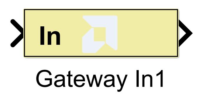
The Gateway In block defines the entry point of a signal into the hardware domain. Any signal that is intended to be implemented in FPGA logic must pass through a Gateway In block.
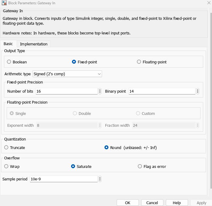
The Gateway In block performs several critical functions. It converts Simulink data types into fixedpoint representations suitable for hardware implementation. It defines the bit width, signedness, and binary point of the signal. It also establishes the sample rate and timing relationship used by the generated logic.
Registered Office: 1 Bunting Street, Newhall, Harlow, Essex, CM17 9GN
Company Number: 9350139
Page 5 of 23
Once a signal passes through a Gateway In block, it is treated as a hardware signal. It becomes subject to clocking, pipelining, and resource optimization during synthesis and implementation. Typical uses of Gateway In blocks include introducing stimulus from a Simulink testbench, feeding modelled ADC data into processing pipelines, and supplying control or configuration signals to hardware subsystems.
Gateway Out
The Gateway Out block defines the exit point of a signal from the hardware domain back into Simulink. It allows hardware results to be observed, logged, and analyzed within the simulation environment.
The Gateway Out block converts fixed-point hardware signals into Simulink-compatible data types. It preserves the numerical behavior of the hardware, ensuring that the observed values accurately reflect the generated RTL implementation.
Gateway Out blocks are essential for verification and debugging. They provide a controlled observation point for monitoring outputs, validating algorithm correctness, and comparing results against reference models.
Typical uses of Gateway Out blocks include capturing processed data for visualization, logging results to the MATLAB workspace, and performing bit-accurate comparisons with golden reference models.
Registered Office: 1 Bunting Street, Newhall, Harlow, Essex, CM17 9GN
Company Number: 9350139
Page 6 of 23

Gateway Blocks for AXI4-Stream Interfaces Versus Standard Gateways
Vitis Model Composer provides different gateway configurations depending on whether a design uses simple scalar signals or streaming interfaces such as AXI4-Stream. While both serve to bridge the Simulink and hardware domains, their behavior and intent differ.
Standard Gateway Blocks
Standard Gateway In and Gateway Out blocks are used for simple, sample-based signals. These gateways transfer a single data value per clock cycle and are typically used for control signals, scalar data paths, and non-streaming algorithmic inputs and outputs.
Key characteristics include:
• One data value per sample
• No explicit handshaking
• Timing defined purely by the Simulink sample rate
• Well suited for control paths, configuration values, and low-rate data
• Gateways mapped directly to simple hardware ports in the generated RTL
AXI4-Stream Gateways
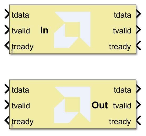
AXI4-Stream gateways are specialized gateway blocks designed to support streaming data paths compliant with the AXI4-Stream protocol. In addition to the data signal, they manage the associated handshake and control signals required for reliable streaming communication.
Key characteristics include:
• Support for continuous or burst-based data streams
• Automatic handling of AXI4-Stream signals such as TVALID and TREADY
• Back-pressure support to manage data flow between producer and consumer
Registered Office: 1 Bunting Street, Newhall, Harlow, Essex, CM17 9GN
Company Number: 9350139
Page 7 of 23
• Natural alignment with DMA engines, video pipelines, and high-throughput DSP systems
• AXI4-Stream gateways that enable Vitis Model Composer designs to integrate seamlessly with AXI-based IP and system interconnects in AMD FPGA platforms
Standard gateways are best suited for simple, non-streaming interfaces where timing is fixed and deterministic. AXI4-Stream gateways are intended for high-throughput, packetized, or continuous data flows where flow control and interoperability with AXI infrastructure are required.
Ports and Interface Definition
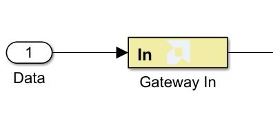
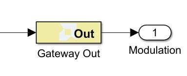
In Vitis Model Composer, ports are defined implicitly through the use of gateway blocks. Each Gateway In or Gateway Out corresponds directly to an input or output port in the generated hardware.
Gateway blocks therefore serve not only as data type converters, but also as formal interface specifications. They define the signal direction, width, and timing at the hardware boundary. This ensures consistency between the Simulink model, the generated RTL, and the integrated FPGA design.
By explicitly defining ports through gateways, designers gain clarity and control over how their hardware modules interact with the surrounding system.
Registered Office: 1 Bunting Street, Newhall, Harlow, Essex, CM17 9GN
Company Number: 9350139
Page 8 of 23
Data Types and Hardware Precision
Data types play a central role in determining the behavior, performance, and resource usage of an FPGA design. Vitis Model Composer relies on fixed-point data types within the hardware domain to enable efficient and predictable implementations.
Gateway In blocks are the primary location where data types are defined. Designers specify the total number of bits, the number of fractional bits, and whether the signal is signed or unsigned. These choices directly influence numerical precision, overflow behavior, and logic utilization.
By making data type definitions explicit at the gateway boundary, Vitis Model Composer enables designers to focus on algorithm development while maintaining full control over hardware accuracy and efficiency.
Registered Office: 1 Bunting Street, Newhall, Harlow, Essex, CM17 9GN
Company Number: 9350139
Page 9 of 23
Flows
Vitis Model Composer supports multiple implementation flows that allow system designers to select the most appropriate level of abstraction for different parts of a design. These flows enable development across programmable logic and AI Engine resources while maintaining a unified, model-based approach. The three primary flows are the HDL flow, HLS flow, and AI Engine (AIE) library flow.
HDL Flow
The HDL flow targets designs implemented at the register-transfer level and is intended for applications that require precise control over timing, resource utilization, and interface behavior. Within Vitis Model Composer, the HDL flow is enabled through a library of synthesizable blocks that represent common hardware functions such as arithmetic operations, control logic, and DSP primitives.
Designers construct hardware architectures graphically in Simulink using these blocks, which directly correspond to RTL constructs. The generated output is synthesizable HDL, suitable for integration into standard FPGA design flows using Vivado Design Tools. Existing HDL modules can also be imported and encapsulated, allowing legacy RTL IP to be reused within a model-based environment.
The HDL flow is particularly well suited to control-oriented logic, filters, simple DSP, finite state machines, and designs where deterministic cycle-accurate behavior is essential. It provides a familiar methodology for hardware engineers while benefiting from the higher-level simulation, verification, and system integration capabilities of Simulink.
HLS Flow
The HLS flow enables designers to describe hardware functionality using high-level programming abstractions, typically C or C++. This approach is well suited to algorithm-centric designs where functionality is more naturally expressed in software-like form, such as signal processing, image processing, or mathematical computation kernels.
Within Vitis Model Composer, HLS blocks represent these high-level functions and are composed into a system-level model alongside HDL or AI Engine components. During code generation, the highlevel descriptions are synthesized into RTL using high-level synthesis techniques. This process allows architectural trade-offs, such as pipelining and parallelism, to be explored through configuration rather than manual RTL restructuring.
The HLS flow reduces development time and lowers the barrier to entry for software-oriented engineers, while still producing hardware implementations suitable for FPGA deployment. It is especially effective when combined with optimized libraries, such as Vitis acceleration libraries and domain-specific libraries, which encapsulate best-practice implementations.
Registered Office: 1 Bunting Street, Newhall, Harlow, Essex, CM17 9GN Company Number: 9350139 Page 10 of 23
AI Engine Library Flow
The AI Engine flow targets the AI Engine array available in AMD Versal Adaptive SoCs. AI Engines are specialized vector processors optimized for high-throughput, low-latency signal processing and machine learning workloads. The AI Engine library within Vitis Model Composer enables designers to model, simulate, and generate AI Engine applications using a dataflow-oriented approach.
Designs are constructed using AI Engine kernels and graph-based constructs, which define how data moves through the AI Engine array. These kernels are typically written in C++ and leverage vector processing and DSP capabilities of the AI Engine architecture. Vitis Model Composer manages the integration of AI Engine components with programmable logic elements implemented using HDL or HLS flows.
The AI Engine flow is particularly suited to compute-intensive DSP and AI workloads such as filtering, transforms, and beamforming. It allows designers to exploit the heterogeneous compute resources of Versal devices while maintaining a single, coherent system model.
Deployment to Hardware Using AMD Vitis™ Model Composer
Once functional correctness has been verified through simulation, Vitis Model Composer enables a direct path from model to hardware. This deployment flow supports both hardware-in-the-loop (HIL) verification and generation of reusable IP cores for integration into Vivado Design Suite-based designs. By maintaining the Simulink model as the primary design artifact, consistency between simulation and implementation is preserved.
Hardware-in-the-Loop Verification
Hardware-in-the-loop verification allows a portion of the design to execute on physical FPGA hardware while remaining connected to the Simulink simulation environment. This approach enables early validation of real hardware behavior, including timing, resource usage, and interface interaction, without requiring a fully integrated system.
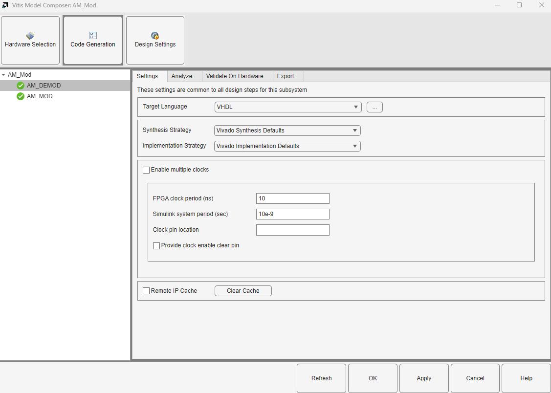
Using the Vitis Model Composer Hub, designers select the target device or evaluation board and choose a hardware co-simulation mode, typically over JTAG or ethernet. The selected subsystem is then compiled, synthesized, and implemented for the target platform. Once programmed, the FPGA executes the hardware portion of the design, while Simulink continues to provide stimulus and capture results.
From the user’s perspective, the hardware-accelerated subsystem behaves like a standard Simulink block. Inputs generated in Simulink are driven into the FPGA, processed in real hardware, and the outputs are returned to the simulation for analysis and visualization. This allows direct comparison between purely simulated results and hardware-executed results, significantly reducing integration risk.
Hardware-in-the-loop verification is particularly valuable for validating:
• Fixed-point behavior and numerical precision
• Interface timing and handshaking
• Performance characteristics under realistic clocking and data rates
Registered Office: 1 Bunting Street, Newhall, Harlow, Essex, CM17 9GN
Company Number: 9350139
Page 11 of 23
IP Core Generation for AMD Vivado™ Design Suite Integration
In addition to co-simulation, Vitis Model Composer supports the generation of standalone IP cores suitable for use within Vivado Design Suite block designs. This enables Vitis Model Composer designs to be deployed as production-ready hardware components.
The process begins by encapsulating the desired functionality within a Simulink subsystem. Interface blocks define how the subsystem connects to the wider system, for example using AXI4-Stream for data movement or AXI4-Lite for control and status. The Vitis Model Composer Hub is then configured to generate an IP core targeting the selected device or platform.
During code generation, Vitis Model Composer produces synthesizable RTL, interface logic, and metadata required for IP packaging. The resulting output is a Vivado Design Tool-compatible IP core that can be added to an IP repository and instantiated like any other vendor or custom IP.
Within Vivado Design Tools, the generated IP can be connected to processing systems, memory controllers, and other logic using standard block design flows. Software running on an embedded processor can interact with the IP through memory-mapped registers or streaming interfaces, enabling seamless hardware–software integration.
Registered Office: 1 Bunting Street, Newhall, Harlow, Essex, CM17 9GN
Company Number: 9350139
Page 12 of 23
Benefits of the Deployment Flow
By supporting both hardware-in-the-loop verification and IP core generation, Vitis Model Composer provides a flexible deployment strategy that scales from early validation to final system integration.
Key advantages include:
• A single model serving as the source of truth from simulation to hardware
• Early detection of hardware-specific issues through HIL testing
• Rapid creation of reusable, production-quality IP
• Tight integration with standard Vivado Design Suite and implementation flows
This deployment capability completes the model-based design workflow, enabling designers to move efficiently from algorithm development to verified hardware implementation.
Example Application: AM Modulation and Demodulation Using the HDL Flow
This example demonstrates the use of the Vitis Model Composer HDL flow to implement a complete amplitude modulation (AM) and demodulation chain. The objective is to show how classical signalprocessing architectures can be captured at a high level in Simulink, verified through simulation, and automatically translated into synthesizable RTL suitable for FPGA deployment.
Registered Office: 1 Bunting Street, Newhall, Harlow, Essex, CM17 9GN
Company Number: 9350139
Page 13 of 23
Amplitude Modulation is one of the simplest modulation schemes to generate and demodulate. While it is inefficient in terms of bandwidth and power, it remains in use for applications such as broadcast radio and aviation communications. Its simplicity makes it an ideal starting point for understanding more advanced modulation techniques and for demonstrating model-based FPGA development.
The example implements both a transmitter and a receiver and supports modulation of either a single-tone signal or digitally generated data. To avoid unintended RF emissions, all signal transfers between hardware platforms are assumed to be conducted via coaxial cabling, with no over-the-air transmission.
AM Transmitter Architecture
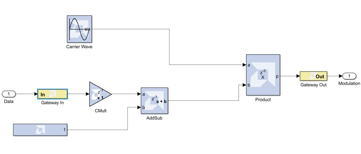
The AM transmitter is based on a straightforward mathematical relationship. A carrier waveform is generated locally, and its amplitude is varied in proportion to the information signal. This is achieved by multiplying the carrier by a scaled version of the input data with an applied DC offset. All transmitter functionality is implemented using blocks from the AMD toolbox within Simulink and encapsulated within a dedicated subsystem. Only logic contained within such subsystems is eligible for HDL code generation.
A sine wave generator block is used to create the carrier signal, configured for a frequency of 20 MHz. The overall design operates at a clock frequency of 100 MHz, providing sufficient oversampling margin.
The data to be transmitted is first passed through a gateway block, which converts MATLAB data types into fixed-point representations suitable for hardware implementation. This ensures deterministic behavior and explicit control of bit widths.
The signal is then multiplied by a constant value to define the modulation index. For this example, the modulation index is set to 1.0. A DC offset is added using an AddSub block to ensure that the carrier remains present when the input data is zero, preventing envelope distortion.
The final AM waveform is generated by multiplying the carrier with the offset data signal. The result forms the transmitter output.
Registered Office: 1 Bunting Street, Newhall, Harlow, Essex, CM17 9GN
Company Number: 9350139
Page 14 of 23
Top-Level Integration and Verification
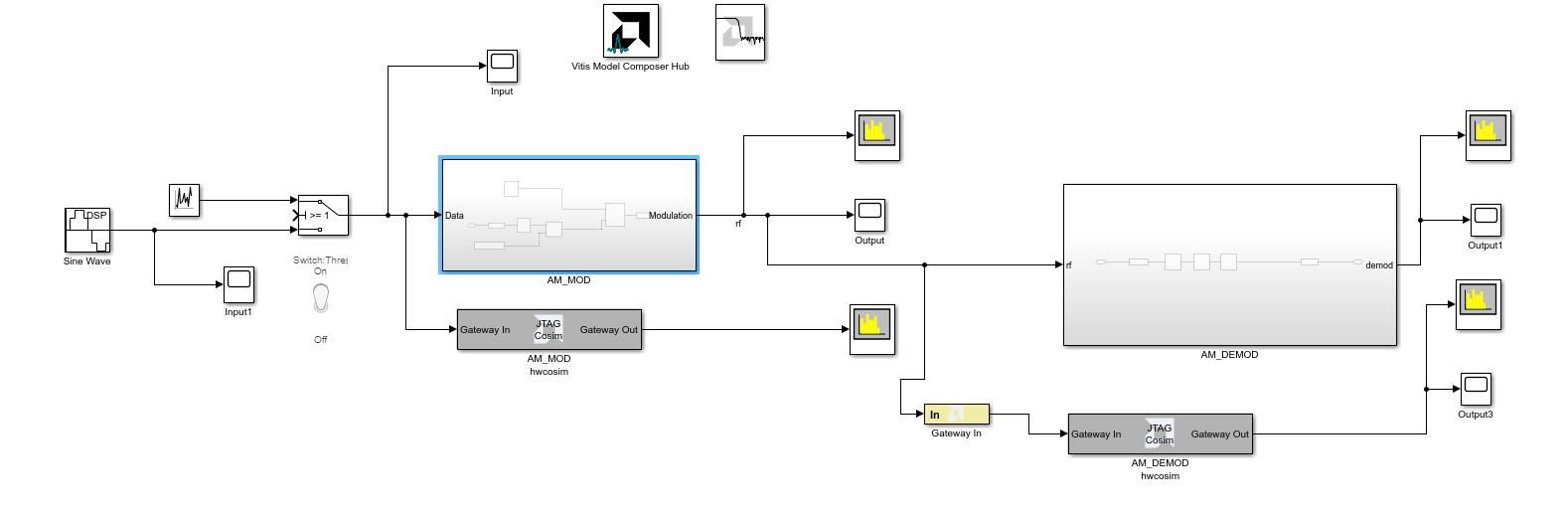
At the top level, the design integrates stimulus generation, signal observation, and the Vitis Model Composer Hub. The Hub is used to select the target device or board, configure the HDL flow, and control RTL generation and hardware verification.
Two signal sources are provided for testing:
• A 500 kHz sine wave
• A random data source
A switch selects between these inputs, allowing evaluation of the modulator under both narrowband and wideband conditions. Scopes are used to observe time-domain behavior, while an FFT block is used to inspect the frequency spectrum.
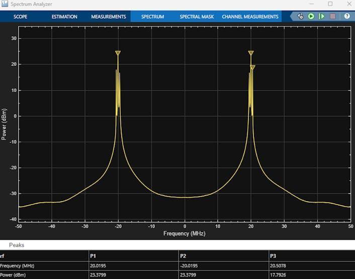
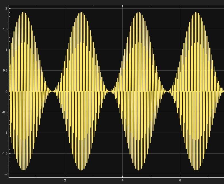
When the sine wave is selected, the output spectrum clearly shows a carrier at 20 MHz with upper and lower sidebands at ±500 kHz. The time-domain waveform exhibits the expected AM envelope. When random data is selected, the carrier remains visible, but the modulation energy is spread across a wider bandwidth.
Registered Office: 1 Bunting Street, Newhall, Harlow, Essex, CM17 9GN
Company Number: 9350139
Page 16 of 23
AM Demodulation Using an Envelope Detector
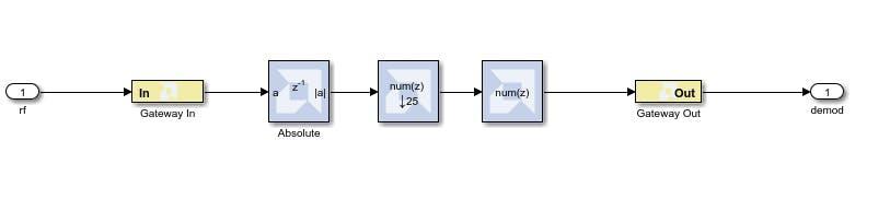
The receiver is implemented using a simple envelope detector, again constructed within a dedicated HDL subsystem. The architecture consists of rectification followed by low-pass filtering.
The incoming AM signal is first passed through an absolute value block to extract the envelope. Two filtering stages are then applied. The first operates at the full 100 MHz sample rate and performs both low-pass filtering and decimation, reducing the sample rate to 4 MHz. The second filter operates at 4 MHz and applies a tighter low-pass response with a passband of 500 kHz and a stopband starting at 600 kHz.
Filter coefficients are designed using the filter design and analysis tool and stored in the MATLAB workspace, allowing easy refinement without modifying the hardware structure.
With a 500 kHz input tone, the demodulated output shows a clear spectral component at 500 kHz, along with a DC component due to the absence of DC removal. When random data is transmitted, the recovered signal is clearly observable in the time domain, with baseband energy spread across the expected bandwidth.
HDL Generation and Deployment
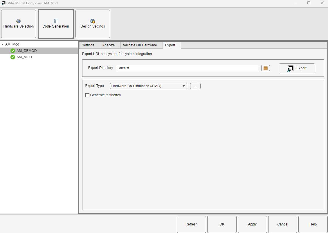
After functional verification, the HDL subsystems are exported using the Vitis Model Composer Hub for hardware-in-the-loop testing via JTAG co-simulation. RTL code and a complete FPGA project are generated automatically. Resource utilization reports show modest logic usage, demonstrating the efficiency of the HDL flow for classical DSP designs.
Having verified the correct operation of the AM modulation and demodulation algorithms in simulation, the next stage in the workflow is to move toward hardware-in-the-loop (HIL) verification. This step is critical, as it allows the designer to validate that the generated hardware behaves identically to the simulated model while executing on real FPGA fabric.
For this example, an AMD Kintex™ 7 FPGA KC705 Evaluation Board was selected, as it was readily available during development. However, it is important to note that this flow is not board-specific. Vitis Model Composer supports deployment to a wide range of AMD FPGA and adaptive SoC platforms, allowing the same methodology to be reused across devices.
Registered Office: 1 Bunting Street, Newhall, Harlow, Essex, CM17 9GN
Company Number: 9350139
Page 17 of 23
Enabling Hardware Co-Simulation
To begin the hardware generation process, the Vitis Model Composer Hub was opened within the Simulink design environment. The AM Modulator subsystem, which encapsulates the transmitter logic, was selected as the design element to be exported. Within the Vitis Model Composer Hub configuration, the export type was set to Co-Simulation (JTAG)
This option instructs Vitis Model Composer to automatically:
• Generate synthesizable RTL from the Simulink model
• Create a Vivado Design Suite project targeting the selected board
• Build a complete FPGA bitstream
• Enable JTAG-based communication between Simulink and the physical hardware
Once initiated, the toolchain runs Vivado Design Suite in the background to synthesize, implement, and generate the bitstream for the target FPGA.
Registered Office: 1 Bunting Street, Newhall, Harlow, Essex, CM17 9GN
Company Number: 9350139
Page 18 of 23
Integrating the Hardware Block into the Model
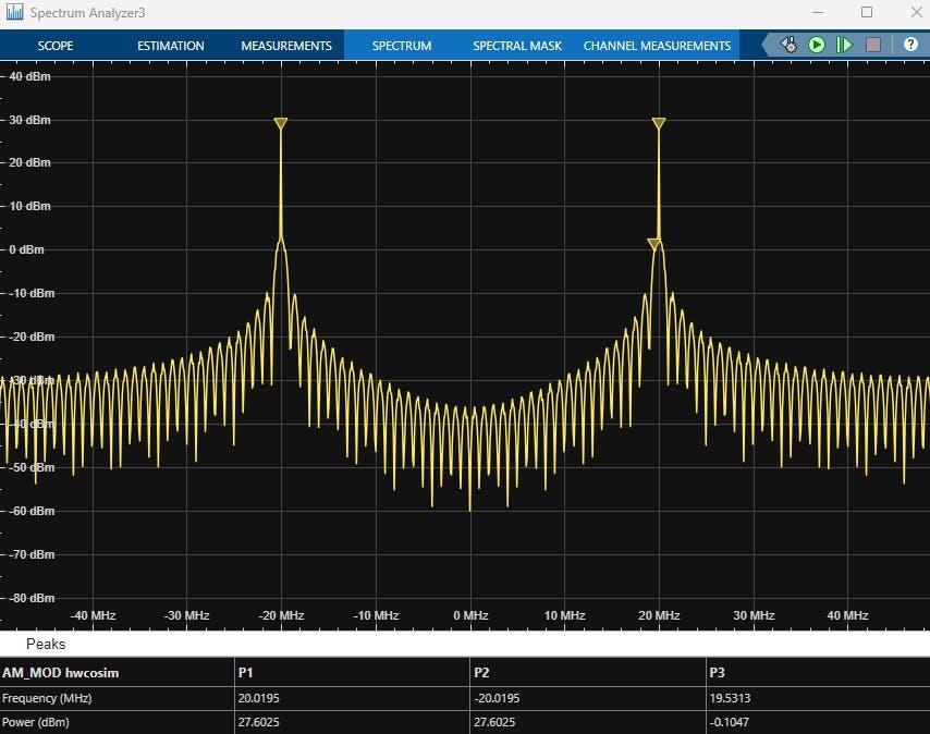
After the build process completes, Vitis Model Composer automatically generates a new hardwarebacked block and places it into a user library. This library can then be saved and reused in other projects.
The generated co-simulation block was then dragged into the top-level Simulink model. At this point, the block represents the actual FPGA implementation, not a behavioral or cycle-approximate simulation.
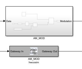
The inputs of the hardware block were connected to the same signal sources used previously for simulation, while the outputs were connected to an independent spectrum analyzer and timedomain scope. This allows direct comparison between simulated and hardware-executed results.
Running Hardware-in-the-Loop Simulation
When running the simulation with the co-simulation block in place, execution time is noticeably longer than pure Simulink simulation. This is expected, as data is now being transferred over JTAG to the physical FPGA, processed in hardware, and returned to Simulink for analysis.
Despite the additional latency, the observed results closely match those obtained during simulation. In particular, the FFT output shows the expected carrier and sidebands, confirming that the modulation process is operating correctly in hardware.
Registered Office: 1 Bunting Street, Newhall, Harlow, Essex, CM17 9GN
Company Number: 9350139
Page 19 of 23
Example: FFT Acceleration Using AMD Vitis™ Model Composer
This example demonstrates how Vitis Model Composer can be used to develop, simulate, and deploy a signal-processing algorithm targeting the AI Engine (AIE) array in Versal Devices. While AI Engines are often associated with machine learning acceleration, they also provide a highly efficient architecture for classical DSP workloads such as filtering, beamforming, and Fast Fourier Transforms (FFT). This makes them well suited to applications in radar, communications, and high-performance signal processing.
The selected example implements an FFT using the AI Engine libraries provided with Vitis Model Composer. The design is based on one of the reference tutorials supplied by AMD, which includes both a Simulink reference model and an AIE implementation. The objective is to demonstrate how a computationally intensive DSP function can be mapped onto the AI Engine array using a modelbased approach, without requiring the user to manually write low-level AIE C++ code.
The application targets a Versal platform and focuses on validating algorithm correctness, performance, and deployment flow rather than device-specific optimization.
The development process begins in Simulink, where the top-level model contains an AIE subsystem representing the FFT function. This subsystem is constructed using blocks from the AMD toolbox that are explicitly designed to target AI Engines. These blocks internally map to highly optimized AIE kernels that take advantage of the vector DSP extensions within each AI Engine tile.
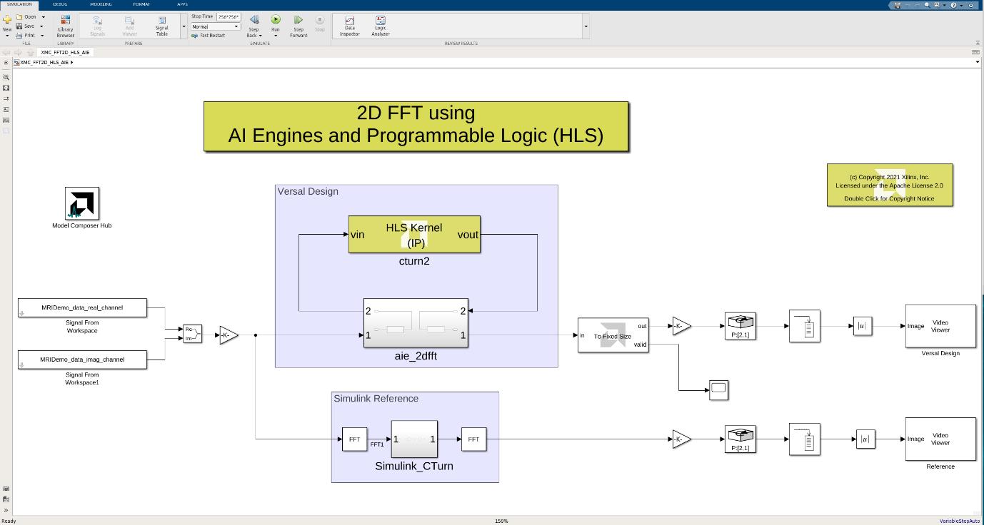
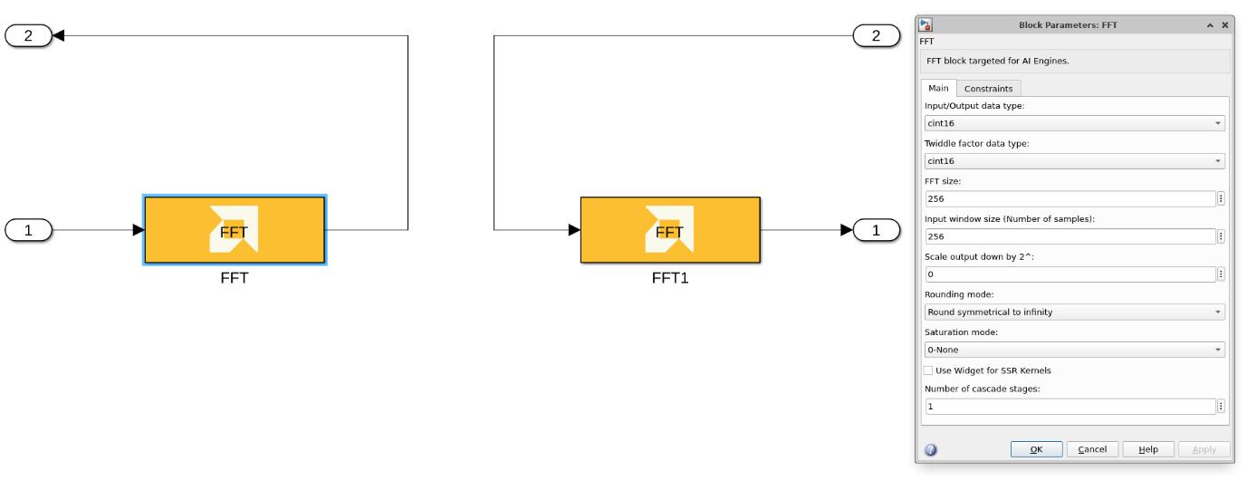
Within the model, the FFT configuration parameters such as transform size, data type, and streaming behavior are defined graphically. This allows the designer to focus on algorithm-level intent rather than architectural detail. Alongside the AIE subsystem, a Simulink reference model is included to act as a golden model for functional verification.
Registered Office: 1 Bunting Street, Newhall, Harlow, Essex, CM17 9GN
Company Number: 9350139
Page 20 of 23
Simulation at this stage is fast and efficient because it operates at an algorithmic level rather than cycle-accurate RTL. This enables rapid iteration and early validation of functionality.
Once the behavior of the model has been verified, the Vitis Model Composer Hub is used to configure the AIE code generation process. The Hub is a central control point that adapts its options depending on whether the target flow is HDL, HLS, or AIE. For this example, the AIE flow is selected.
Using the Hub, the developer can enable automatic test bench generation from the Simulink stimuli. This test bench is used to run cycle-approximate AIE simulation, allowing comparison between the Simulink reference results and the compiled AI Engine output. The generated reports indicate whether the results match, partially match, or do not match, providing immediate confidence in correctness.
In addition to functional validation, the AIE simulation outputs throughput estimates and performance data. These results can be further analyzed using Vitis Analyzer, enabling deeper insight into kernel execution and data movement within the AI Engine array.
After successful simulation, the same model is used to generate hardware-ready output. Vitis Model Composer supports generating either hardware validation designs or deployable applications targeting bare-metal or Linux environments. In this example, a bare-metal configuration is selected to simplify bring-up and evaluation.
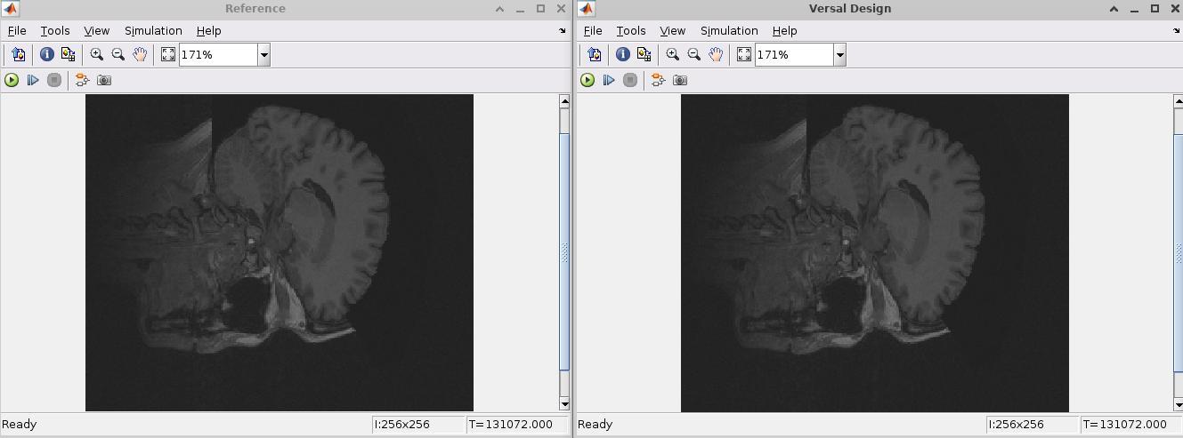
The generated output includes all necessary components to boot the target Versal Platform and execute the AIE application. When run on hardware, the system reports successful execution of the FFT processing, confirming that the behavior observed in simulation correlates with real hardware operation.
Conclusion
The white paper explains how model-based design lets teams move from algorithm to FPGA or adaptive SoC implementation faster and with less risk by using an executable Simulink model as the primary design artifact for exploration, verification, and implementation.
It introduces Vitis Model Composer as the tool that connects MATLAB/Simulink workflows to AMD hardware, outlining three development paths: HDL for deterministic block-based RTL generation, HLS for C/C++ algorithm acceleration and library reuse, and AI Engine for building and deploying vector DSP kernels on Versal Devices. It also covers the essentials needed for reliable results, including ports, data types and fixed-point choices, and built-in visibility for debugging and validation.
Deployment is a core theme, showing how designs can be exported as Vivado Design Suite IP or used for hardware-in-the-loop testing, with AIE outputs generated for Versal Adaptive SoC targets. The paper ties everything together with practical examples (AM modulation/demod, an HLS imageprocessing pipeline using Vitis Libraries, and an AIE FFT example), concluding that Vitis Model Composer provides a repeatable path from concept to verified hardware while reducing iteration time and integration effort.
AMD, and the AMD Arrow logo, Kintex, Versal, Vitis, Vivado, and combinations thereof are trademarks of Advanced Micro Devices, Inc. Other product names used in this publication are for identification purposes only and may be trademarks of their respective companies.
Registered Office: 1 Bunting Street, Newhall, Harlow, Essex, CM17 9GN
Company Number: 9350139
Page 22 of 23