



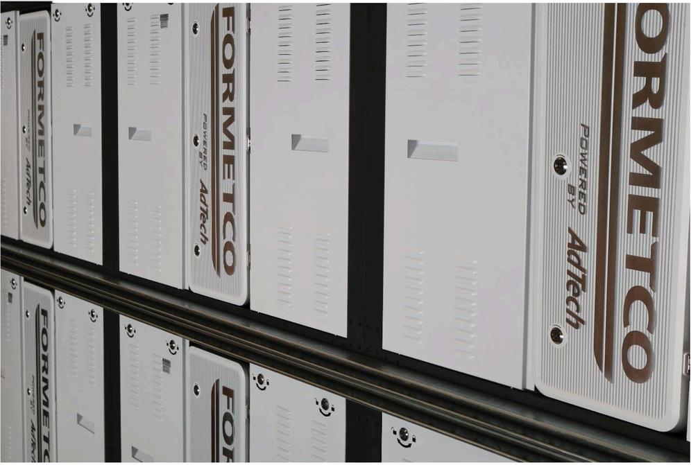
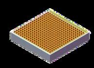
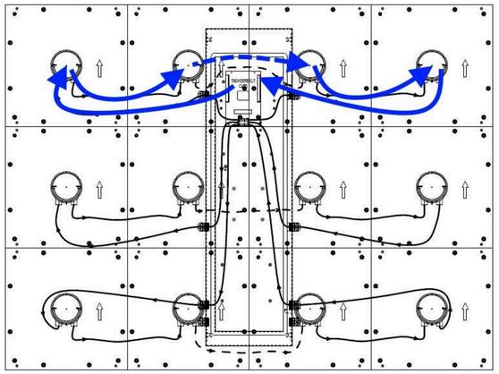
An FTX cabinet is composed of LED tiles, Ethernet cables, tile harnesses, and a power supply box. There are two vented access panels and a door for the power supply box. The tiles and power supply box are waterproof and the vented access panels allow for heat dissipation. Data flows left to right (rear view) row by row. Power flows out of the power supply box through the tile cables on both sides and then from tile to tile towards the middle of the cabinet FTX cabinets come in 4 different sizes
3x3: 3 high, 3 wide, 9 tiles, 2 power supplies
3x4: 3 high, 4 wide, 12 tiles, 2 power supplies.
4x3: 4 high, 3 wide, 12 tiles, 2 power supplies.
4x4: 4 high, 4 wide, 16 tiles, 3 power supplies.

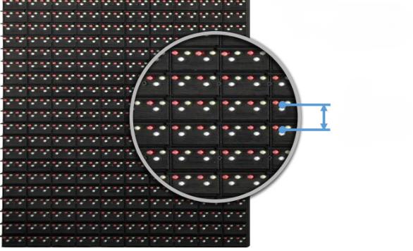
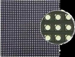
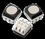
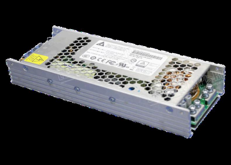
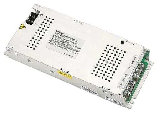
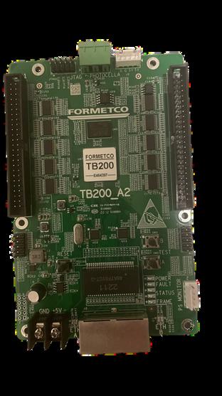
Each FTX cabinet has one power supply box The IP66 rated power supply box is where the electrical components that power and control the tiles are located including the power supplies, thunderbolt and hub cards. It is also where all connections are made inside the cabinet. There is one Thunderbolt card in each power supply box that controls the tiles for the cabinet It also receives and transmits the video signal to neighboring cabinets via the two Ethernet ports on the bottom of the card The hub card, where the tile harnesses connect, is mounted onto the top of the Thunderbolt card
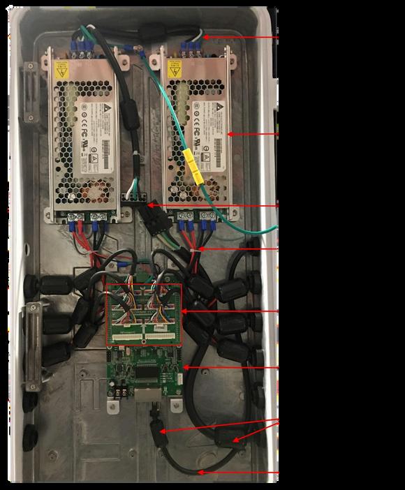
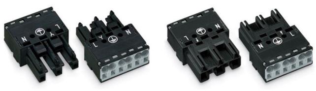
The WAGO connector is a black, two-piece power connector in each power supply box It is the main power disconnect for the cabinet This should be disconnected prior to replacing any parts in a power supply box.
The Thunderbolt card is the controller card for the cabinet it resides in this is the card that talks with the computer and tells the modules what and how to display This also tells the computer what diagnostic issues there are so that we can determine any issues before a tech is sent on site. There are two types of Thunderbolt cards. Thunderbolt and TB200. They are not compatible with each other. The TB200 is the new, more powerful device.
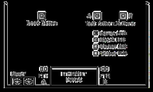
Use Thunderbolt card LED indicators to interpret the controller’s status as follows:
POWER: When green light is active, the controller has power
RESET: Hitting the reset button activates the red RESET light, indicating the controller is being power cycled
STATUS: If green light is on, the controller has loaded successfully.
ETH A & B:
Normal operation: one port will have red and green flashing fast and alternating, the other port will have green light flashing fast
Red light is flashing fast: data is traveling to that port, and out to the other port.
Green light is flashing fast: data is passing through the cable successfully
Green light is on solid: a cable is plugged in.
Red light is solid: a cable is plugged in, but the PC has not connected to it.
If both the green and red light flash simultaneously at a steady rate: the cable plugged into that port is bad.
To manually power cycle the controller, press the RESET button. The RESET light will glow red when the button is pressed, followed by the controller restarting
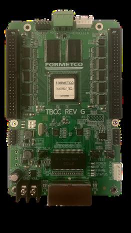
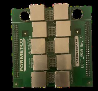
The Hub card allows the Thunderbolt card to communicate to the tiles. There are several types of hub cards depending on the tyoe of tile that the Thunderbolt card is talking to. The Hub card attaches directly to the Thunderbolt card and the harnesses plug into the ports on the Hub card.
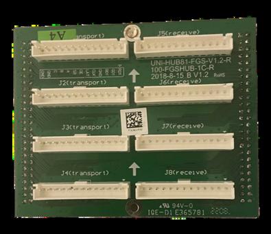
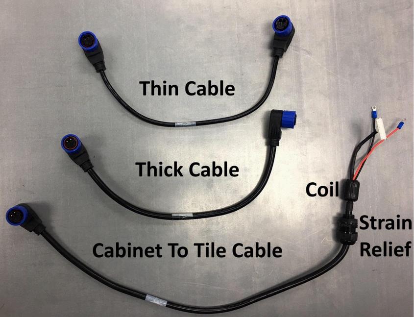
There are three different types of tile harnesses in each cabinet and they are NOT interchangeable
Thin Cables – Tile to Tile
• 5/16 Inch in diameter
• Sometimes have red cable sheathing at the ends (not pictured)
• Passes data only between two tiles
Thick Cables – Tile to Tile
• 7/16 Inch in diameter
• Passes power and data between two tiles
• Blue tile connector on one side, Molex connector and red & black DC power wires on the other
• Connects tiles to the hub card inside the power supply box
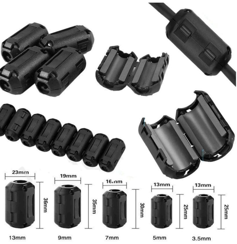
• Must have coils installed on them inside the power supply box
There are 5 main components in the FTX data flow: PC, video switch, Thunderbolt Cards, Hub Cards, and LED tiles. There is one Thunderbolt Card per cabinet. Each Thunderbolt Card has a hub card attached to it that distributes data through the LED tiles in that cabinet
1.PC: Sends video signal out through an Ethernet port
a Signal travels through an Ethernet cable from the PC to the video switch
2.Video Switch: Ethernet switch that distributes the video signal into two Ethernet cables labeled “A” and “B ” Cable B plugs into port B of the Thunderbolt card in the last cabinet of the data flow.
a Signal travels through cable A to data port A of the Thunderbolt card in cabinet 1 (top left, rear view).
3 Thunderbolt Cards: One card per cabinet Distributes the video signal via the hub card through the LED tiles in each cabinet.
4.The Hub card is attached directly to the Thunderbolt card and distributes a.Signal travels through single cable harnesses, one per row, from LED tile to tile (left to right, rear view) and returns to the hub card for diagnostics
5 The signal is passed from Thunderbolt card to Thunderbolt card via Ethernet cable
a.Once the signal arrives at the last Thunderbolt card in the chain, the signal returns to the video switch via cable B.
b The signal returns to the PC via the single Ethernet cable between the video switch and the PC.
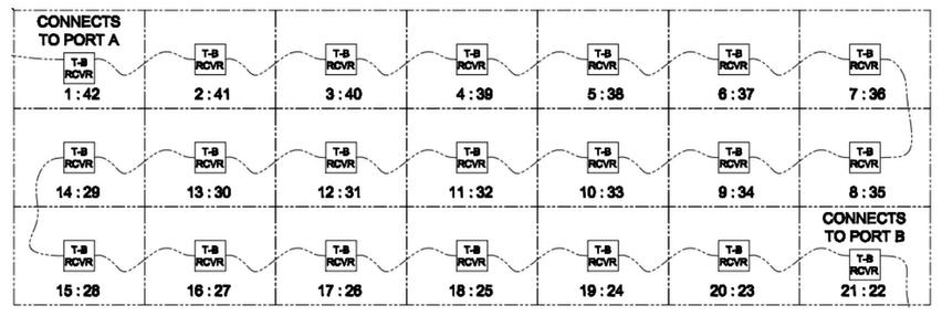
Both cables A and B are capable of transmitting data signal and operating the entire sign. If there is a break in the Ethernet chain between Thunderbolt cards, both cables will push data up until the break. This means any single failure, or chain break, between Thunderbolt cards will not cause a visual outage. If there are two breaks in the data chain, video will not be displayed between them
Video displayed properly by cable A
Video displayed properly by cable B
No Video – Blank Cabinets
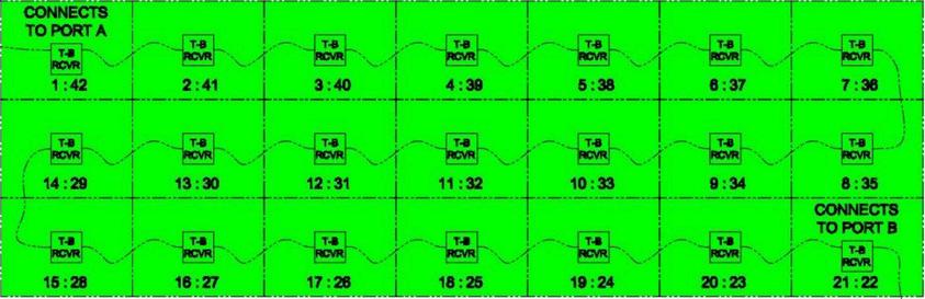
Figure 1 – Normal Operation – Visual Operating Percentage 100%
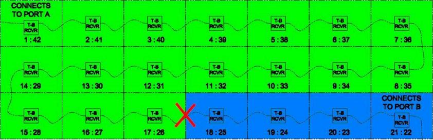
Figure 2 – Single Chain Break – Visual Operating Percentage 100%
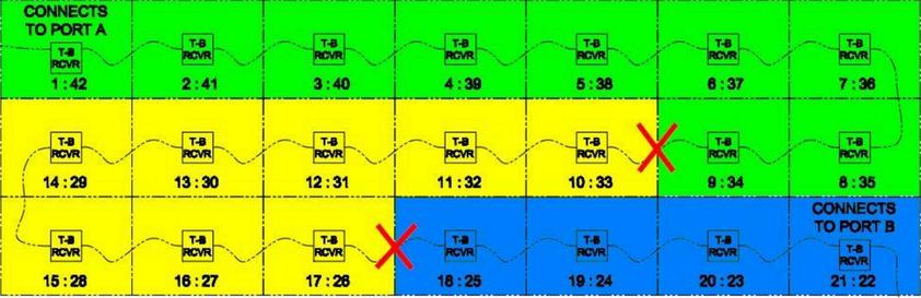
Figure 3 – Double Chain Break – Visual Operating Percentage 62%
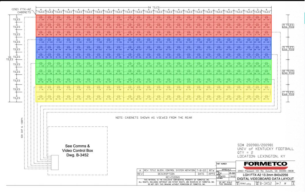
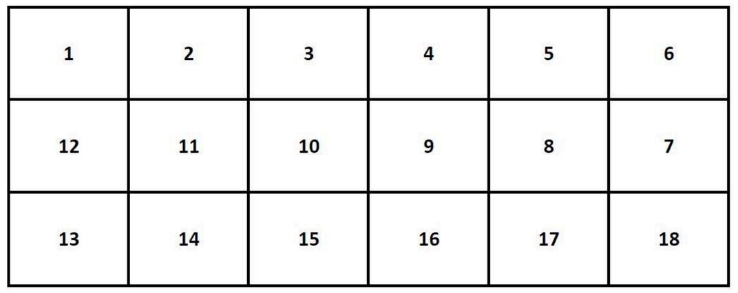
F4X & FTX CABINET NUMBERING -REAR VIEW
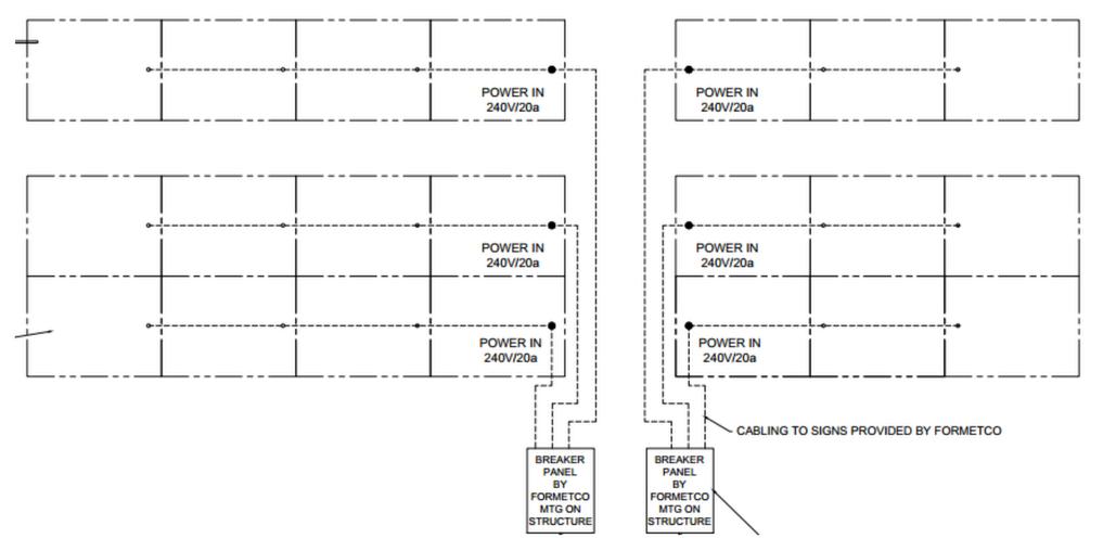
Power flows from the outside in on both sides of each row of tiles. There is no power connection between the middle tiles
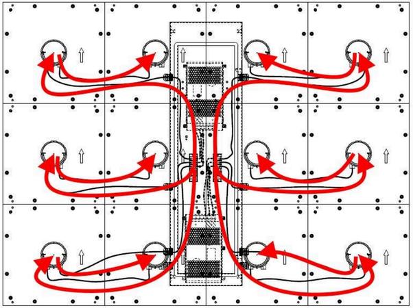
Data begins on the left row of Ethernet ports of the hub card. The signal goes to the leftmost tile (rear view) and the travels left to right across the row The signal returns to the right row of Ethernet ports on the hub card from the rightmost tile (rear view).
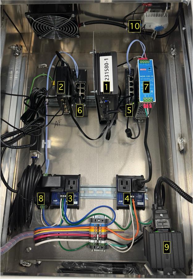
1 PC: Control boxes can be built with a single PC, or with two PC’s A control box with two PC’s is called a Primary-Secondary setup. The secondary is a backup. In control boxes with a backup PC, the primary PC is marked with gold and the secondary PC with silver Their power supplies and power cables are marked the same way to make them easier to trace. Whenever replacing a PC, the power supply should also be changed. There are two Ethernet ports on each PC and they are not interchangeable LAN 1 is the video port and LAN 2 is the communications port (this is standard for silver DFI PC’s but can vary on older PC’s) If the cables are reversed in the ports, the sign will not work, but it will not cause damage. Never power down a PC by removing the power plug from the back of the PC Instead, unplug the AC connector for the power supply
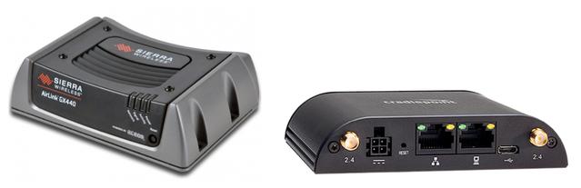
2.Router: The router allows us to communicate with the display remotely, reports diagnostics, and retrieves data The router is plugged into a communication switch via an Ethernet cable. While the router allows communication back and forth from the outside world, the switch acts as a hub and allows communication between the router and the devices inside the control box. When utilizing an operator supplied router, the operator is responsible for communication based maintenance. This includes power cycling, SIM card reseating, SIM card replacement, and device replacement
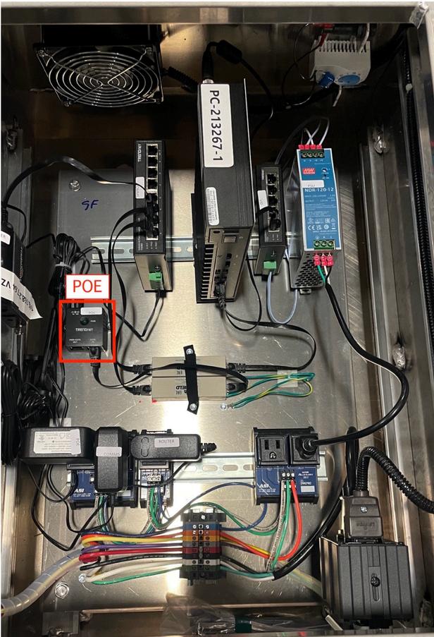
3 Comms Power Relay: This is a device that can be triggered by the SmartLink to power cycle the POE device that provides power to the camera This has the effect of power cycling the camera itself.
4 PC Power Relay: This is a device that can be triggered by the SmartLink to power cycle the PC, Video Switch, Comms Switch, and the Router.
5 Video Switch: This is a 5 port Gigabit unmanaged switch The video switch is simply an expansion of the video port on the PC Imagine it as a multi outlet extension cord There is a short Ethernet cable ran between LAN1 of the PC and the video switch. Data is carried to the display from the video switch by longer Ethernet cables Because this switch is unmanaged, video connections can be made in any port of the switch.
6 Communication Switch: This is a 8 port Gigabit switch The communication switch (sometimes shortened to comms switch) is simply an expansion of the comms port on the PC Imagine it as a multi outlet extension cord There is a short Ethernet cable ran between LAN2 of the PC that goes into the communication switch. The switch is a hub that allows the PC to communicate with the backup PC (if installed), router, and Camera This switch also Provides POE power for the camera
7.12V Power Supply: This device is a power supply that is powering the Video Switch and PC
8.48V Power Supply: This device is a power supply that is powering the Comms Switch.
9 Isoblok Surge Suppressor: Provides surge protection on the power coming into the control box. The “Protection Present” and “Line Ok” lights should be green at all times. The red “Fault” light should never be on If the red indicator light is on, there is likely a bad ground or the polarity is reversed. This part can be bypassed if it fails by removing it and plugging the UPS power cable directly into the duplex outlet underneath Any trained technician can change this part because it plugs directly into the outlet. An electrician is recommended to troubleshoot if there is a wiring issue
10.Thermostat & Fan: There is an exhaust fan in the top of the cabinet. It will not always berunning because it is connected to a thermostat that is set to 95°F
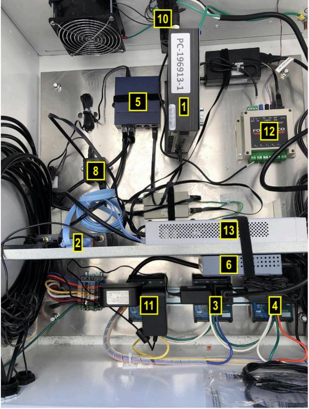
11.Video Switch relay: This is a device that can be triggered by the SmartLink to power cycle the video switch.
12.CPS12: This is a networked device that can provide 12v power to multiple devices and also contains an intrusion detection device to disable the output to the screen
13 Fortinet: This is a network firewall that replaces the comms switch in clear channel boards. Port 7 is used to go to the second control box in a back to back configuration. Ports 1-6 are for all our networked devices in the control box.
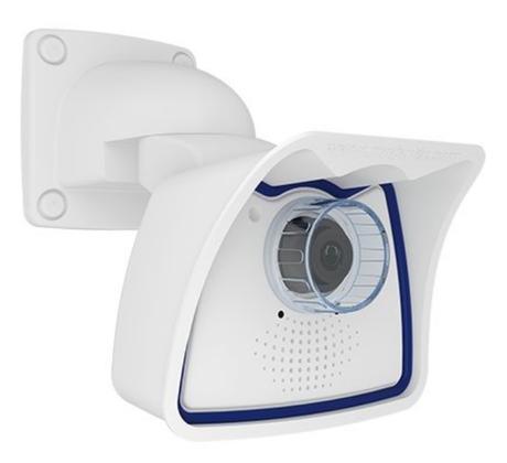
14 Mobotix Camera: This is a camera that is used to view the face of the board so that customer support can diagnose issues. It is powered by POE so there is only one cable running to the camera
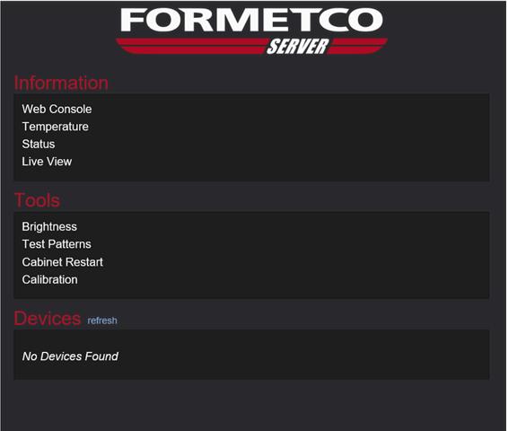
Servcom is the software we use to control all of our FTX and F4X signs. It is used in billboards, information centers, and scoreboards. This software takes the image as one of a few input styles and sends the information out to the board and tells the board how to interpret and display the content. It also talks to the board and reads diagnostic data about the board that can then be sent back to our Network Operations Center (NOC) Servcom also has the ability to change preset values suchas brightness to ensure a uniform image. This allows us to create a great user experience all with only one software Servcom can take an image in through a few methods The most common methods are screen rake and video capture Screen rake is the ability to grab an image from the desktop screen or a content player. There are several content players that can all be used as servcom is just taking a specified portion of the desktop screen and capturing that Video capture takes in the information from a capture card such as a Blackmagic mini recorder and scales it to the board Diagostics is also a large portion of what Servcom does It talks to all the components that make up the board and knows when there has been a failure. Servcom then communicates this failure to our NOC so that a service technician can be dispatched Servcom will alert the NOC exactly what part has failed and if the issue is visual or not. Servcom also allows the NOC to adjust presets and calibrations. This allows for brightness ramps to be adjusted allowing for the sign to be the correct brightness for the time of day in its specific environment. It also allows for the sign to be calibrated to adjust for parts that have been swapped out This lets the board continue to look uniform even after
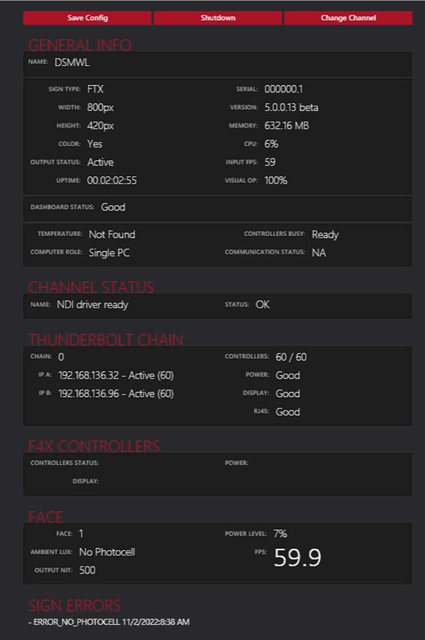
The web console is the main hub of servcom It is where the user can get most of the important information about the sign at a single glance. This includes the name, serial number, size, version, resources used, input channel, data chain information, and frames per second amongst other things
This shows the temperature of each of the thunderbolt cards in a sign.
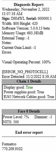
This will show the status of any errors on the board along with other current information about the live status of servcom. It will show errors and the cabinets they are in
This shows what content should be being displayed on the board
This window shows the brightness information for the board. It will show the minimum and maximum brightness of the board and show the brightness ramp profile that is currently set. Usually for billboards it is set on profile 5 and for scoreboards it is set on profile 9 The higher the profile number the more aggressive the brightness profile will be in keeping the brightness of the sign high
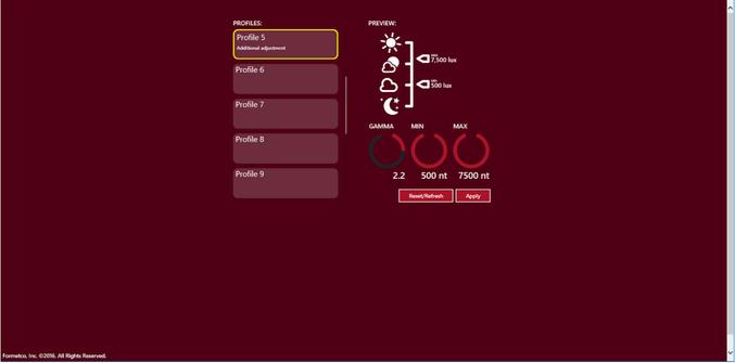
This window allows the user to put test patterns across single cabinets and across the whole board This is useful for identifying types and locations of issues and for ensuring a uniform look across the screen.
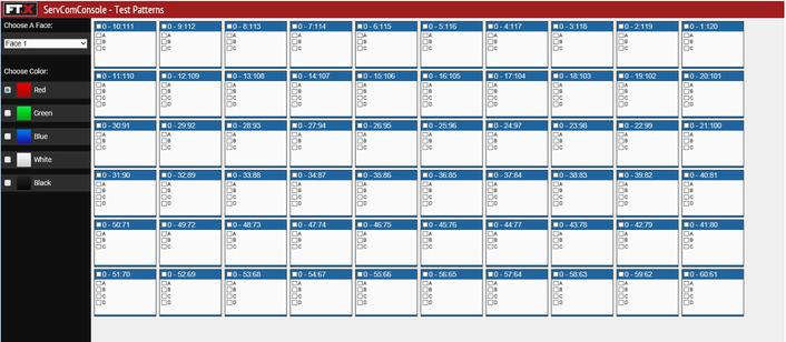
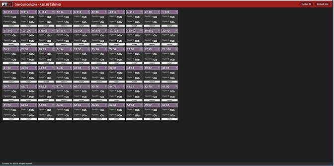
This window allows the user to restart each thunderbolt card individually if needed. It also allows the user to see the data transmission speed being used by each card It should be 1GB for each card.
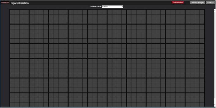
This screen allows the user to select individual tiles and calibrate their brightness to match the surrounding tiles You can select the tile that needs to be calibrated and then adjust the brightness of red, blue, and green individually down to match the surrounding tiles. Then you can save the calibration
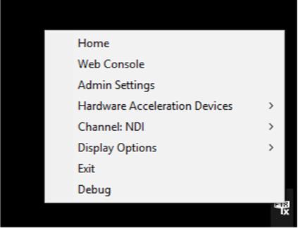
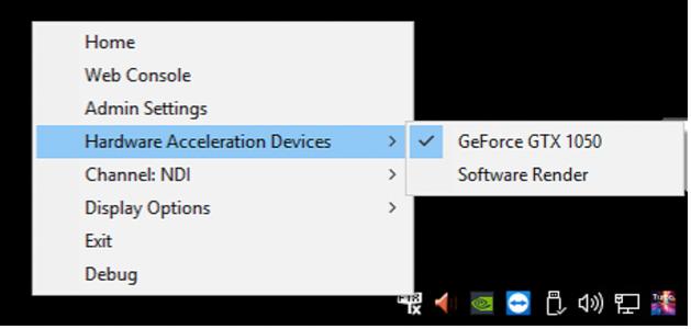
This menu allows the user to select the graphics card or the internal graphics to be used for processing For best performance select the graphics card
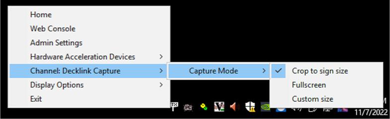
This menu allows you to select the scaling that is used for the content going to the board. This also lets you choose sources for NDI.
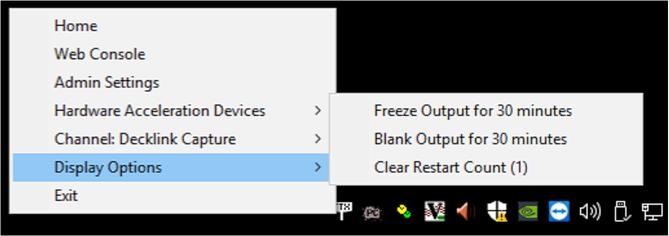
This menu allows for the user to freeze or blank the output for 30 minutes.
If there is one tile with discoloration, chsnge the tile If there are multiple discolored tiles then change the first discolored tile in the data flow (right to left, front view).

Reset the data cables of that row on the hub card Switch the data cables of that row on the hub card with another row. If the issue on the display moves, then change the hub card. If the issue does not move then change the first tile in the data flow. If this does not resolve the issue, change the tile harness
Check the power and Ethernet connections inside the power supply box for the row of tiles that is out
Confirm 4.2VDC on the terminal block across the red and black wires for that row. Switch the data cables for that row on the hub card with another row If the issue on the display moves, then change the hub card If the issue does not move then change the first tile in the data flow. If this does not resolve the issue, change the tile harness
Change the power supply that is off.



Verify the Thunderbolt card in that power supply box has its lights on If not, change the power supply in the cabinet does not have its LED lit If the thunderbolt card does have power, reseat the two Ethernet cables on the bottom of the card and cycle power to the cabinet by disconnecting and reconnecting the WAGO connector in the bottom of the cabinet.
Verify that there is power to the cabinets that are out
Reseat the Ethernet cables between cabinets where the outage begins

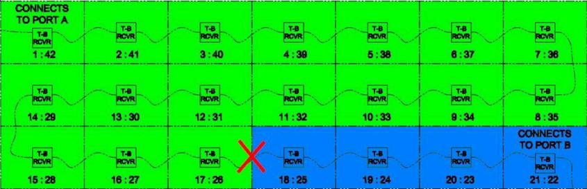
There will be no visual error in this case Reseat the Ethernet cables to the Thunderbolt cards the break is between. If the signal doesn’t recover, replace the Ethernet cable. See the Thunderbolt Indicator Lights section for verification
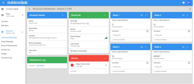
SmartLink is a device that is used to remotely monitor and power cycle power to different devices in our control box. The SmartLink device has its own modem and interface built into it so that customer support can log in to the device even if the sign comms are down There are four separate relays in a SmartLink box. Each of these relays can be used to cut power to a specific device on the board. The device that each relay controls varies based on customer and age of the board. A relay is a switch that can turn power off and on by a command.
The web interface can be logged into and the status of each relay can be seen. Any recent alerts can be viewed and power status can be seen.
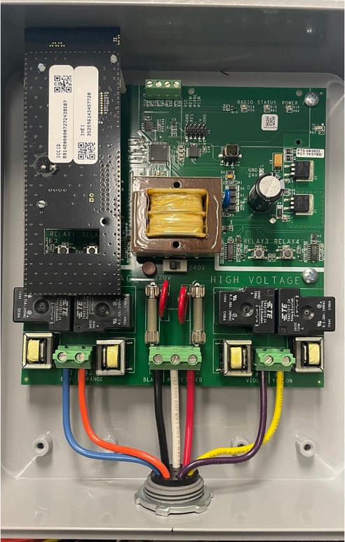
Power Flows into the bottom center of the SmartLink board. This powers the SmartLink device as well as provides the power that is switched by the relay
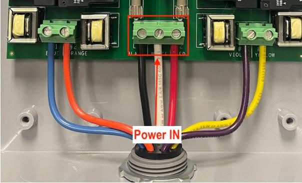
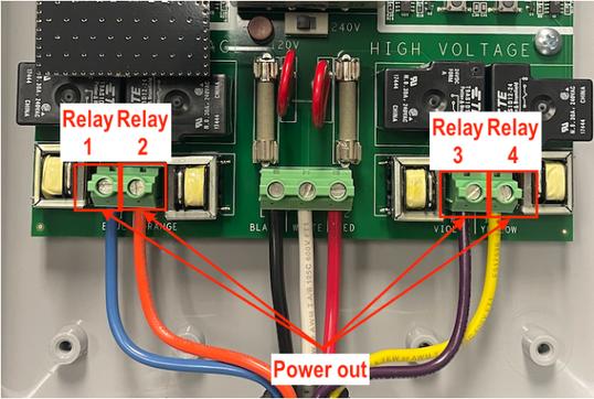
Power from the 4 relays flows out of the bottom left and bottom right of the SmartLink board. You should be able to meter 120v from any of the blue, orange, purple, or yellow wires to the white wire.
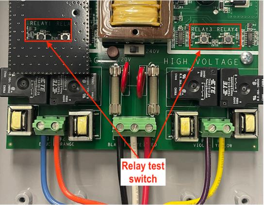
There is a button for each relay to toggle power on and off This allows for the tech to turn on and off power to different devices and test the functionality of the SmartLink
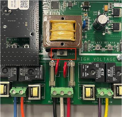
There is a switch to select the power input voltage. This should be selected to 120v. with this selected you should be able to meter 120v from the red wire to the white wire, 120v from the black wire to the white wire, 0v from the black wire to the red wire
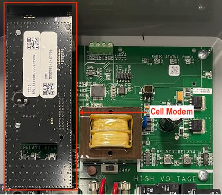
There is a black card on the upper left side that is the cell modem. This is what allows the SmartLink device to communicate with the OutdoorLink website This card may be a different color depending on the cell signal type.
LHR ( Left Hand Read) and RHR (Right Hand Read) are how we tell which side of the board is which If you are driving down the road that the board is on and you look out the left side of the car to see the board it is a left hand read.
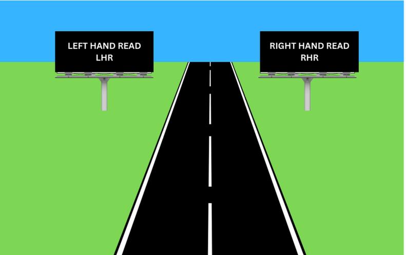
This is important information because our control boxes and cameras are programmed from the factory to be set up for one specific side. This allows us to know where the diagnostic issue is coming from and allow for easier service in the future
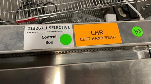
On each control box and on each camera there is a serial number For example 213267 1 the 1 at the end means that it is a LHR control box or camera If the serial number ends in a .2 that means that it is a RHR. We have also started putting stickers that say LHR and RHR on both the control boxand the camera
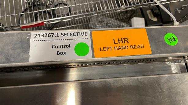
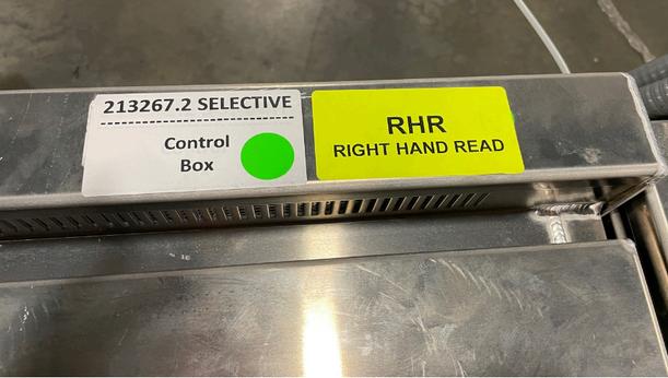
On each control box and on each camera there is a serial number For example 213267 1 the .1 at the end means that it is a LHR control box or camera. If the serial number ends in a 2 that means that it is a RHR We have also started putting stickers that say LHR and RHR on both the control boxand the camera.
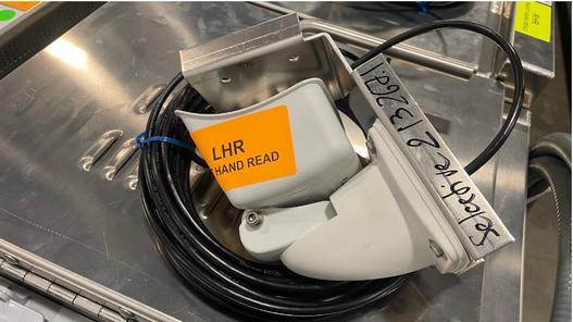
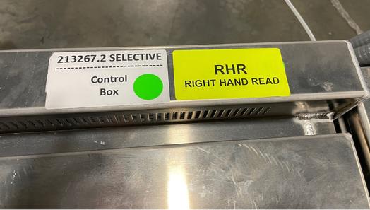
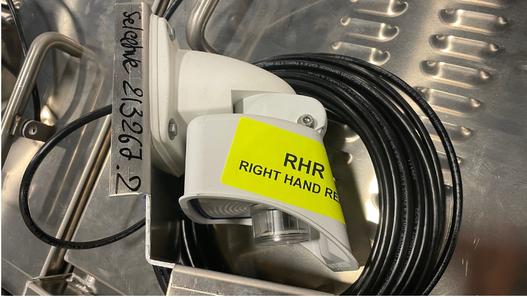
Orders are shipped together usually on the same trailer This will include the crated sign sections, imprints, spare parts container, control box, contactor box, trim, camera arm, camera arm bracket, camera (in spare parts box), and hardware
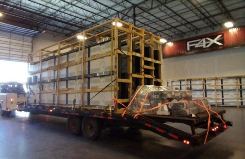
Signs are crated up into shipping sections for ease of transport. These sections are specific as to where they go.
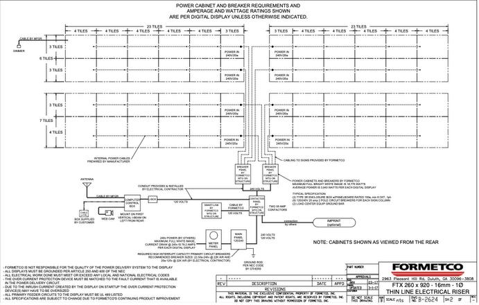
On the crate for each section there is a map as to where these sections go.
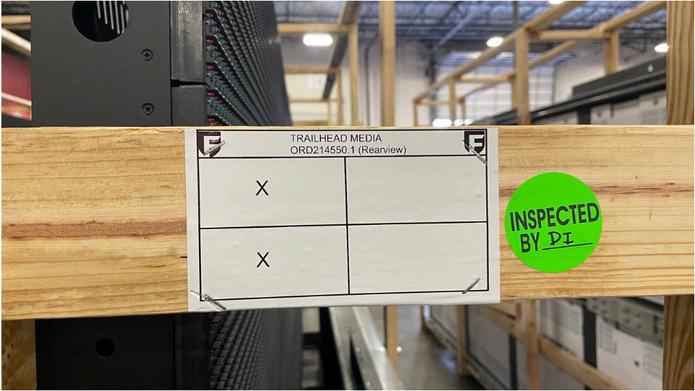
This will tell you the company name, order number, LHR or RHR, and where the sections in that crate are supposed to go. I typically open this crate first with my left hand shipping sections and start flying the bottom left section first Section identification is pretty easy Top left section will have the photocell in it and the coiled up ethernet cable labeled A on it.
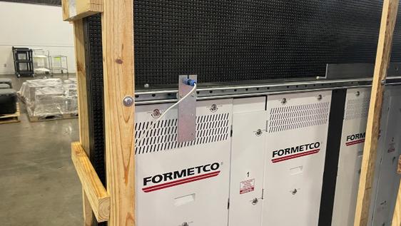
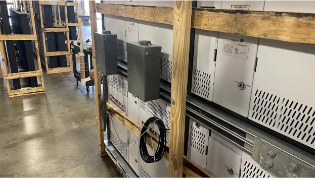
Breaker panels will be on the bottom sections and will be towards the center of the board.
During installation of the board the bottom sections should be flown first followed by the top sections.
Measurements should be taken so that the board sits centered on the structure. Keep in mind that the shipping sections are not all the same size
The first section should be set in place and then the mounting clips should be tightened down to hold it in place Do not over tighten these
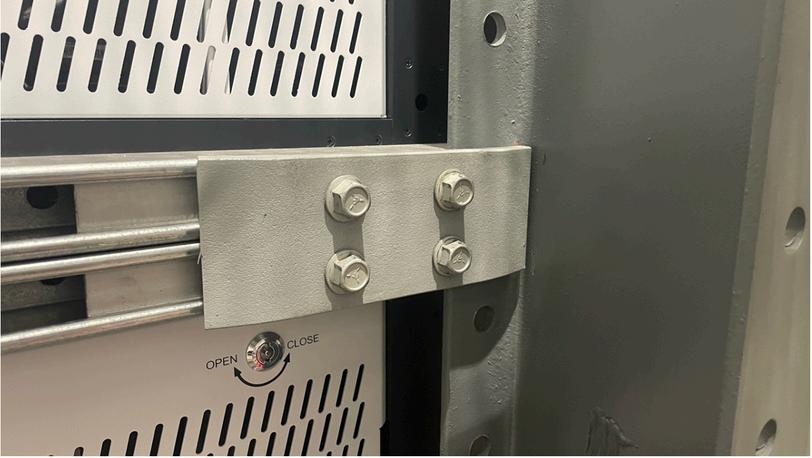
The next section should be lifted in place and the clips should be loosely placed around the beams but not tightened yet. While the crane is still attached the stitch bolts and nuts should be installed and tightened between the sections (3 per cabinet)
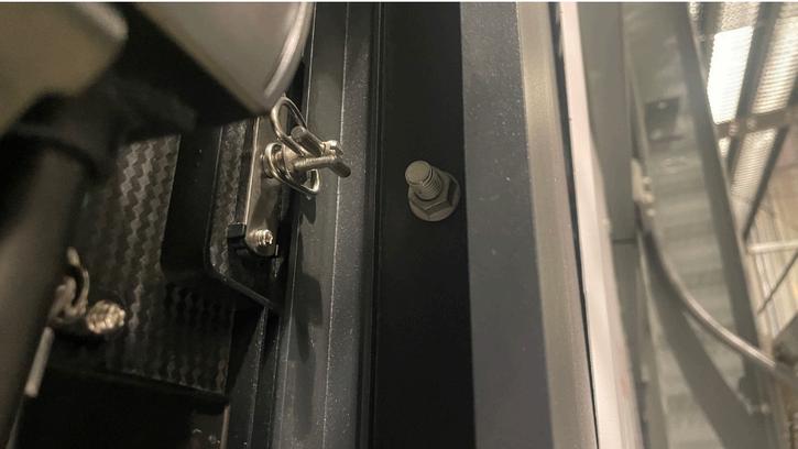
Only once the stitch bolts have been tightened should the mounting clips be tightened. This helps prevent any gaps between the sections Only once the stitch bolts and mounting clips are tight can the crane let go of the section and all lifting brackets be removed.
When flying the upper sections the section should sit down on the lower section and align on the alignment pins. The mounting clips should be loosely placed around the beans but not tightened yet The down bolts (4 per cabinet) should be installed into the threaded holes and tightened between the sections
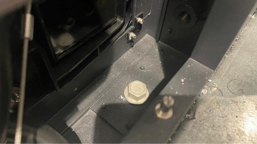
Only once the down bolts have been tightened should the mounting clips be tightened. This helps prevent any gaps between the sections. Only once the down bolts and mounting clips are tight can the crane let go of the section and all lifting brackets be removed
Once all the sections are installed the crossover cables and drop down cables can be installed. Each cabinet that has a crossover cable and drop-down cable should be labeled. These will have a pass through already on the cable and should be inserted into the data hole in the corresponding control column. Once installed it should be plugged into the TB card.
The Control box is the brain of the board It should be labeled LHR or RHR. Make sure that the box is placed on the correct face. The control box should be attached to one of the beams on the bottom level of catwalk. Ensure that the door to the control box can swing open all the way
Both coiled up ethernet cables (A and B) should be run to the control box and in through the cable passthrough and into the box
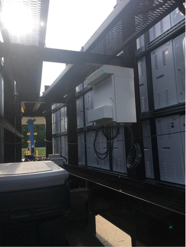
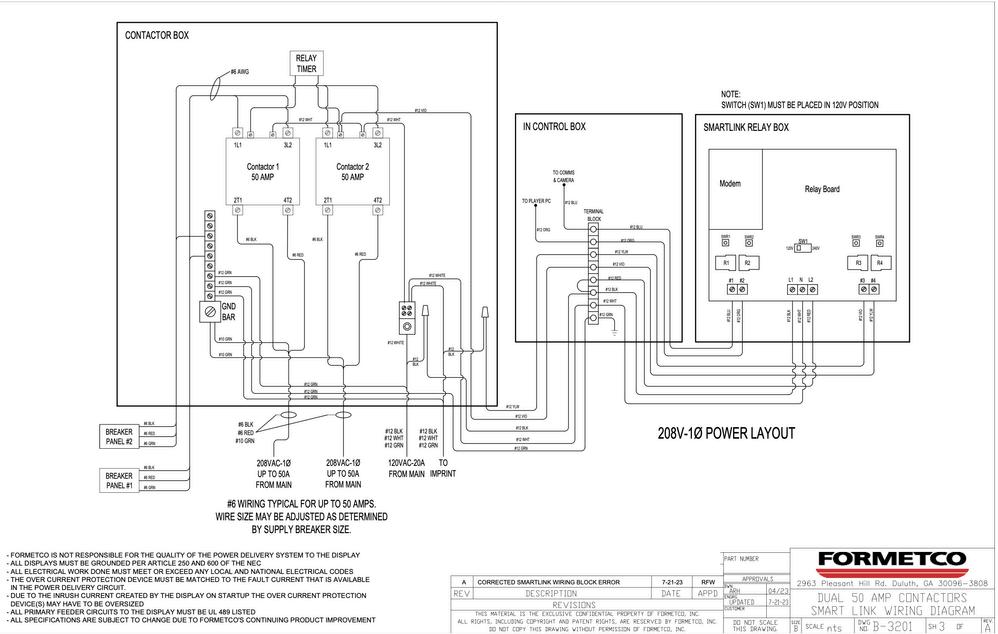
The Contactor box should be attached to the back of a beam on the first level of catwalk It should be within reach of the coiled up flexible conduit on the control box. This conduit should be run from the control box to the contactor box.
This is where the electrician will run the main power into and power out of to the subpanels
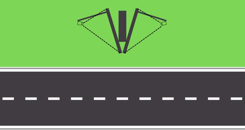
The camera is mounted to the camera arm with included hardware. The arm should be mounted away from the road
The camera arm bracket gets mounted to the bottom of the farthest out I beam
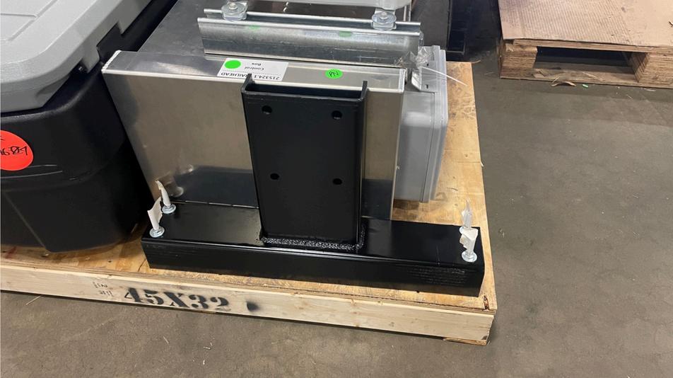
The arm is clamped by the u bolts and slid out as far as it will go.
To aim the camera place your phone on the lens of the camera and turn on the front facing camera Then adjust the camera position until the face of the board is in the center of the camera.
Run the ethernet cable from the camera up to the control box and plug into the POE device
Manual tile calibration is typically done when replacing a single module in an FTX sign Calibration typically needs to be done when replacing modules in a screen that has been in operation for two or more years Face orientation will play a role in determining when a module replacement will require calibration. The process will allow editing of the individual brightness profile of each color, Red, Green and Blue
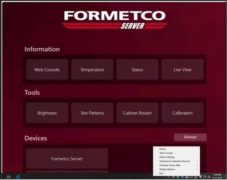
1. Right Click the FTX Icon in the System Tray of the Desktop
2 Select Home
3. Select Calibration on the Home Menu
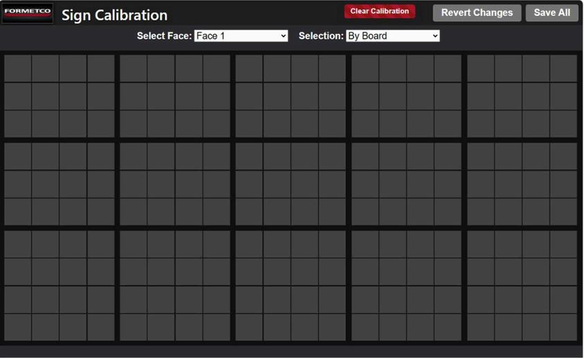
The calibration screen has the following controls:
1 Clear Calibration – Removes the calibration from any previously done modules
2. Revert Changes – Clears any Calibration done on the current session.
3. Save All – Selected once you are done editing for the current session.
4 Select Face – Used only if working on a unit that has multiple faces that have content replicated typical on On-Premises Signage.
5 Selection – Allows calibrating an entire cabinet or individual Board (Module) Full cabinet calibration is seldom used.
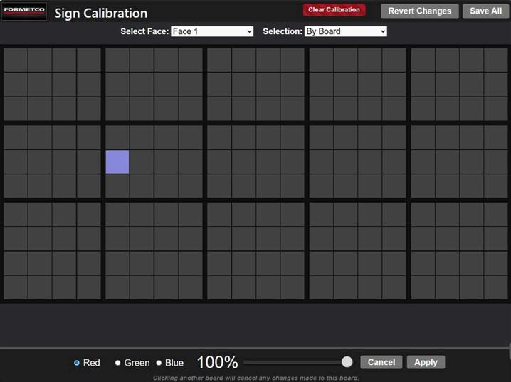
1. Use the mouse to select individual modules. When the module is selected, the entire cabinet will illuminate From this you can determine the selection of the correct module.
Notes:
1.Optimally, put the new module near the bottom corner in front of the camera.
a This allows any future-needed calibrations of the module to be done remotely
b.While calibrating, position yourself as safely near the center of the readership cone as possible
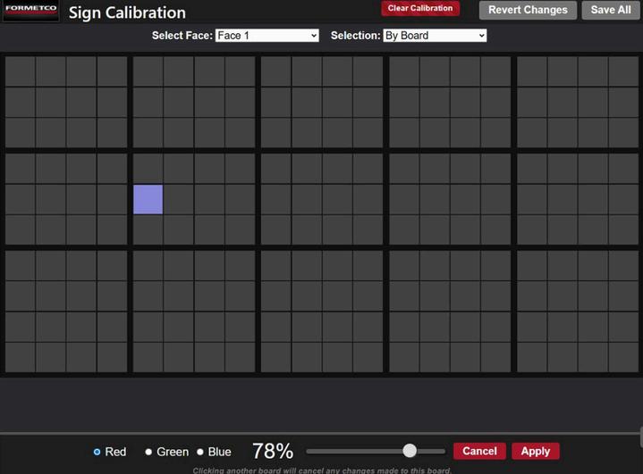
1. Once the module to be calibrated is Highlighted, use the slide bar on the bottom for adjustment. Left and Right arrows can also be used for granular movement
2. Selection can be made between Red, Blue and Green.
3 Once each color has been done, enter Apply to save the edit Hitting Apply must be done for each color
4. Once all edits have been completed, hit Save All on the top right.
5. Once the Save has been completed, navigate to the Home Page and run through Test Patterns to Clear the patterns
6. Once Complete, please contact the Formetco NOC to capture the Calibration File for backup purposes.