Fluorolined Equipment Pvt.Ltd.
"The answer to Corrosion"
Precision Engineered
Reliable
Economical 1
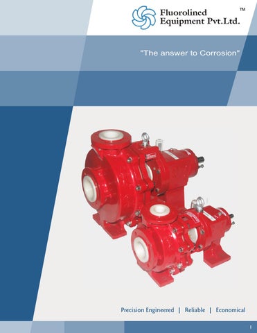
About Company Fluorolined Equipment Pvt.Ltd. is a leading manufacturer of centrifugal chemical Process pumps in specialized Fluoropolymers for handling of various corrosive liquids. The company has been serving nearly 80 % of Indian steel industry and other chemical industry since last a decade. We serve a wide range of sizes of pumps in solid injection molded PVDF material as well in vertical submersible pumps.
Introduction of PVDF The fluorinated polymers are widely appreciated for their remarkable chemical inertness and their excellent resistance to aging. Polyvinylidene Fluoride (PVDF) offer the specific advantages of easy processing in accordance with all the convention methods used in the plastic industry. PVDF, polymerized, according to its own special process, offer a high degree of crystallinity to the that by other processes, resulting among other things in superior thermo-mechanical properties. The intrinsic technical superiority is one of the reasons for the success of which PVDF has achieved on the world market for more than 20 years But nothing is possible without a genuine quality assurance policy which Fluorolined Equipment follows with their efforts for Total Quality Management over their products & services.
Special Properties of PVDF
Advantages Tried & tested chemical process pump design for rough condition. Thick walled vaccum-proof PVDF housing in one piece. Therefore no additional sealing points in the pump housing. PVDF casing liner completely encapsulated in strong cast iron Casing Armour. Replaceable PVDF Casing liner-reduces the maintenance cost. Pipe line forces are absorbed by Cast Iron Armour. Also suitable for high system pressure. Flanges with through holes meeting the requirement of the chemical industries.
Resistance to most chemicals & solvents
Semi-open PVDF impeller reinforced by large metal insert Smooth running & long service life of mechanical seals, thanks to the particularly heavy duty bearing pedestal.
High thermal stability
Modular system ensuring economical parts stocking.
Mechanical strength at elevated temperature
Available in 1440 as well as 2900rpm.
High purity
Flow rate up to 400m3/hr. Head upto-100 mts.
High abrasion resistance
Back pull out design ease of maintenance.
Resistance to sunlight
Available in 20 models with maximum interchangeability.
Resistance to nuclear radiation
External corrosion protection of pumps & base frames by an epoxy paints.
Low flame & smoke characteristics Resistance to fungus Low permeability to most gases & liquids Readily processible, formable & weldable Cold weather impact strength
Each pump is tested at our computerized test bench. A performance test report is submitted with each pump. Faster deliveries and Cost effective. Consulting & servicing by specialists. Sales & services network all over India.
2
IMPELLER All impellers are semi-open type having contoured flow passages for Maximum efficiency.
CASING LINER Top centerline discharge, self venting volute casing formed out of solid injection molded PVDF.
SHAFT SLEEVE Shaft sleeve of high corrosion resistant materials are used for maximum compatibility with the liquid.
CASING ARMOUR Heavy cast iron armour is encapsulated on the casing liner for maximum mechanical strength.
3
BACK PLATE Thick walled solid injection molded PVDF.
SHAFT Shaft of EN series / Stainless steel material is provided having maximum 0.5mm deflection at mechanical seal.
BEARING HOUSING MECHANICAL SEAL Mechanical seal/ Gland pack arrangements of different systems or makes are provided depending on the
Sturdy cast iron construction provide rigid bearing alignment and shaft support, contains large oil reservoir, oil level is maintained by constant oil leveler with visible oil supply.
4
No compromise with aggressive media : Fluorolined heavy-duty Process Pumps overcome difficult condition! Technical features The development of the heavy-duty series PVDF is based on long-term experiences with the proven KLCPseries. Compared to the KLCP series the very strong shaft design is the substantial construction feature of the PVDF series, but, together with this improvement further important components were designed to supply even more operational safety. The special stable-bearing pedestal ensures smooth running even in case of difficult applications and thus optimum pre-conditions for a long lifetime of the mechanical shaft seal. Referring to the shaft deflection, this robust design provides the pre-conditions to meet international standards, especially in case ofheavy load e.g. starting against open discharge valve, minimum flowrates, maximum impeller diameters and high density. Leakage losses and wear and tear of the rotary seal rings are kept to a minimum due to the low shaft deflection. The wetted contact/liner material PVDF permit applications withall aggressive, corrosive or toxicmedia. By means of their sturdy design with solid PVDF housing completely encapsulated in outer metal armour, they combine the chemical and thermal resistance of the liner material with the mechanical strength of the outer metal armour.
Casing Liner and Back Plate Thick walled casing liner and back plate is made of PVDF Replaceable casing liner Standard shell of cast iron Casing Liner and Back Plate are solid injection moulded
Impeller Semi-openimpeller A large metal insert in the PVDF impeller greatly increases mechanicalstrength
Shaft Sleeve Design is matched to the shaft seal mounting. Non-metallic: - 99.7 % Oxide Ceramic Al2O3 (High Alumina Ceramic) & Silicon Carbide. Metallic: Hastalloy-B/C, Alloy20,Titanium.
Shaft Seal Single mechanical shaft seal of various systems & makes are available. Stuffing boxes and a large range of accessories.
Bearing Pedestal Particularly rigid shaft of high - strength Stainless Steel / EN-8 / EN-19/ EN - 24 / EN-41. Double raw ball bearing with extremely high load capacity. Long life oil lubricated bearings on both the sides
Gaskets Envelope Gasket (Casing Gasket) is of PTFE with EPDM rubber insert to ensure maximum sealing. All other gaskets are of PTFE.
Temperature Ranges In practice, the theoretical maximum temperature specified by the plastic manufacturers cannot be utilized in the case of heavy-duty hydraulically optimized pump components. Thanks to the encompassing metal armour and the generously dimensioned metal impeller core, the PVDF used in Fluorolined Pumps can be stressed to a relatively high extent without becomingmechanically over loaded.
Performance Range Flow rate upto 400 m3/hr. Head upto100mts of liquid coloum.
5
PVDF Series-I (1.375”)
Performance Curves PVDF Series-I (1.375”) Characteristic Curves at 1440 RPM
PVDF Series-I (1.375”) Characteristic Curves at 2900 RPM
24 21 60 PVDF-30 (40 X 25 - 210)
18 50 PVDF-30 (40 X 26 - 210)
PVDF-35 (50 X 40 - 260)
12 PVDF-45 (60 X 40 - 195)
9 6 3
30 20
PVDF-25 (40 X 25 - 150) PVDF-20 (25 X 25 - 125)
0
5
PVDF-40 (50 X 40 - 160)
PVDF-50 (80 X 50 - 160)
10 15 20 3 Capacity in m /Hr
25
PVDF-45 (50 X 40 -195)
40 Head in mts
Head in mts
15
30
10
35
40
PVDF-25 (40 X 25 -150)
PVDF-40 (50 X 40 -160)
PVDF-20 (25 X 25 -125)
0
10
20
30
40
PVDF-50 (80 X 50 -160)
50
60
70
80
Capacity in m 3/Hr
6
PVDF Series-II (1.875”)
Performance Curves PVDF Series-II(1.875”) Characteristic Curves at 1440 RPM
PVDF Series-II(1.875”) Characteristic Curves at 2900 RPM
40 35
Head in mts
25 20 15
PVDF-85 (80 X 50 -315)
Head in mts
30
PVDF-55 (50 X 40 -315)
PVDF-70 (80 X 60 -265)
PVDF-70 (100 X 80 -275)
10 5
PVDF-60 (80 X 50 -195)
0
18
PVDF-80 (100 X 80 -200)
36
54
72
Capacity in m 3/Hr
90
108
126
144
100 90 80 70 60 50 40 30 20 10
PVDF-70 (80 X 50 - 265)
PVDF-60 (80 X 50 -195)
0
20
40
PVDF-80 (100 X 80 -200)
50
60
80 100 120 160 180
200
Capacity in m 3/Hr
7
PVDF Series-III (2.125”)
Performance Curves PVDF Series-III(2.125”) Characteristic Curves at 1440 RPM
50 40
Head in mts
30 PVDF-95 (100 X 80 -360)
20 10
0
20
40
60
80
100 120 140 160 180 200
Capacity in m 3/Hr
8
Series IV High Capacity Pumps for large capacity chemical/metal industry. Details available only on request.
Industries Served Steel Pickling Plants
Caustic Chlorine Plants
Pickling Acid Recirculation, Rinse recirculation Spent/waste acid transfer, fresh acid transfer.
Acid Regeration Plats
Hcl Loading/unloading, chloride destruction, anolyte blowdown, drying tower.
Dyes and Intermediates Plants
Concentrated Waste Pickle Liquor, Pickle Liquior, and fresh acid transfer.
Pesticide /& Insecticide Plants Various kind of toxic & hazard chemicals with or without slurries.
Acidic chemicals with slurries, filter press applicatication.
Pharmaceutical and Bulk Drug pure to slightly contaminated, toxic, explosive or environmentally harmful media such as acids, alkalis and solvents.
Environmental Industrial waste water treatment (ETP), Scrubber recirculation.
9
Shaft Sealing Flexibility Double Mechanical Seal Balanced Double Mechanical Seal Springs are product protected Cartridge Assembly-Easy for installation Ideally suitable for Corrosive Chemicals with Abrasive slurry
Single Mechanical Seal Single outside mounted mechanical seal Teflon bellow Rotary face is of GFT / Replaceable & Reversible Silicon Carbide Stationary face is of Ceramic/Silicon carbide External flushing provided for longer life
Mould Thickness
Bearings
Series - III
Series - IV
PVDF
PVDF
PVDF
PVDF
25
30
35
40
45
50
55
60
65
70
75
80
85
90
95
100
110
120
Casing
7
7
7
9
7
8
9
11
10
11
12
16
12
12
12
15
13
13
13
13
Impeller
15
15
13
15
15
15
15
15
15
19
15
18
17
17
18
19
15
15
20
20
Threading for Impeller
12
13
13
12
13
13
13
14
14
19
14
20
14
16
14
15
14
14
16
16
150
3/4” UNF
1” UNF
1 1/4” UNF
1 1/2” UNF
21.9
31.9
35.9
47.4
Dia. at Bearing Span
43
63
72
75
Dia. at coupling
25
42
45
55
Overhang
215
248
307
240
Max. Shaft Deflection
0.05
0.05
0.05
0.05
34.925
47.625
53.975
63.5
22
32
36
47.5
Radial
SKF-6207
SKF - 6310
SKF - 6311
SKF - 6313
Thrust
ZKL-3306
ZKL - 3310
ZKL - 3311
ZKL - 3313
120
165
205
150
Dia. Under Sleeve
Shaft Sleeve
Series - II
20
Back Plate
Shaft
Series - I
Dia. Outside Dia. Inside
Bearing Span Mech. Seal
Stationary Unit
1.375”
1.875”
2.125”
2.5”
Rotary Unit
1.375”
1.875”
2.125”
2.5”
Oil Seal
In / Out Board
35 X 72 X 10 / 25 X 40 X 40
50 X 80 X 10 / 42 X 60 X 10
55 X 80 X 10 /
65 X 90 X 10 /
45 X 60 X 10
55 X 70 X 10
Casing / Impeller
1-2
2-3
2-3
2-3
Impeller / Back Plate
3-4
3-5
3-5
3-5
Clearance
Construction Details (All dimensions are in mm.)
10
Cross Sectional Drawing
Parts List Sr. No.
Part Name
M.O.C.
Sr. No.
Part Name
M.O.C.
1
Casing Liner
PVDF
*17
Oil Seal
NEOPRE NE
2
BackPlate
PVDF
*18
“O” Ring
NEOPRE NE
Impeller
PVDF
19
Locating Flange
HYLAM
Casing Armour
C.I.
*20
Stationary Unit of Mech. Seal
Ceramic / Sic
Envelope Gasket
C.I.
*21
Rotary Unit of Mech. Seal
GFT / Sic
6
Adaptor
C.I.
22
Deflector
Polypropylene
7
Bearing Block
C.I.
23
Constant Oil Leveler
Polycarbonate
8
Bearing Cover
C.I.
24
Hardware
Steel
Shaft
EN 19 / EN 41 / SS 316
25
Bolt for Clamping Mech. Seal
SS With PP Nut
Shaft Sleeve
Ceramic
26
Oil Breather
Steel
11
Ball Bearing (Inboard)
SKF - 6207/6310/6311/6313
27
Oil Drain Plug
Steel
12
Ball Bearing (Outboard)
ZKL - 6306/3310/6311/3313
28
Coupling**
C.I.
13
Circlip
Spring Steel
29
Drip Tray
Poly Propylene
14
Star Washer
Steel
30
Base Plate**
M.S. Fabricated
15
Locknut
Steel
31
Casing Hardware
S.S.
*16
Oil Seal
Neoprene
32
Bearing Block Leg
C.I.
*3 4 *5
*9 *#10
# Different Sleeve material available for different fluids - SiC/ HAST-B/ ALLOY20/TITANIUM * Parts normally stocked for emergency repairs. ** Parts not shown in Cross Sectional view
11
Modular Interchangeability Chart Pump Model/Size (Suct. dia X Del.dia X Imp. dia.) in mm
Casing Armour with Liner
Impeller
Stuffing box (Backplate)
Adaptor
Shaft, Bearing block & Leg Assembly
Group / Series
PVDF20 (25 X 25 X 125) PVDF25 (40 X 25 X 150) PVDF30 (40 X 25 X 210) PVDF35 (50 X 40 X 260) PVDF40 (50 X 40 X195)
Series - I
PVDF45 (50 X 40X 160) PVDF50 (80 X 50 X 160) PVDF55 (50 X 40 X 315) PVDF60 (80 X 50 X 195) PVDF65 (80 X 50 X 230) PVDF70 (80 X 50 X 265) PVDF75 (100 X 80 X 230)
Series - II
PVDF80 (100 X 80 X 200) PVDF85 (80 X 50 X 315) PVDF90 (100 X 80 X 275) PVDF95 (100 X 80 X 350) PVDF100 (150 X 100 X 290)
Series - III
PVDF110 (80 X 50 X 400) PVDF120 (150 X 125 X 280) PVDF150 (150 X 125 X 320)
Series - IV
12
Vertical Submerged Pump-VSP Series Heavy Duty Engineered Polypropylene/PVDF Sump-Pump for Primary Effluents/Corrosive Liquids and Scrubbing System: Heavy duty design Thick walled Volute casing & Back plate Semi-open Impeller with large metal insert
All hard ware are of Polypropylene with metal insert Available submerged Length-0.5 mts, 1.0 mts,1.5 mts,2.0 mts & 2.5 mts Maximum head- 30 mts, Maximum flow-30 m3/hr
Shaft sealing not required Specialized CFT bush bearing at bottom end of shaft to minimize shaft deflection.
*Technical details available on request. WARANTEE CLAUSE : We stand guarantee only the genuinety of PVDF Resign in our pumps but do not stand guarantee for any kind of chemical, physical, & toxicological effects on the same by the liquid handled with our pumps. Since the conditions of handling and useare beyond our control, we make no guarantee of results. We assume no liability for injuries, damages or penalties resulting from its use whether or not our recommendations are followed. Our recommendations are only on the basis of our past experienceand should not be taken as guarantee.
Part List For VSP Pumps No. Description
M.O.C.
Qty.
1
Voute Casing
POLYPROPYLENE
1 NO.
2
Back Plate
POLYPROPYLENE
1 NO.
3
Impeller
POLYPROPYLENE
1 NO.
4
Cage Ring
POLYPROPYLENE
2 NOS.
5
Back Plate Bush
CARBON FILLED TEFLON
1 NO.
6
Shaft Sleeve
HAST-B/CERAMIC
1 NO.
7
Shaft With HDPE Sleeve
En8 / HDPE
1 NO.
8
Column Pipe
HDPE
1 NO.
9
Discharge Pipe
HDPE
1 NO.
10
Discharge Flange
POLYPROPYLENE
2 NOS.
11
Discharge Elbow
POLYPROPYLENE
1 NO.
12
Elbow Flange
POLYPROPYLENE
1 NO.
13
Pump Support Plate
M.S. with PP LINING
1 NO.
14
Motor Support Stool - Bottom
C.I.
1 NO.
15
Motor Support Stool - Top
C.I.
1 NO.
16
Bearing Cover - Bottom
C.I.
1 NO.
17
Bearing Cover - Top
C.I.
1 NO.
18
Ball Bearing
SKF - 6207
1 NO.
19
Ball Bearing
SKF - 7306
1 NO.
20
Oil Seal (35 X 60 X 10)
NEOPRENE
3 NOS. 1 NO.
21
Oil Seal (25 X 40 X 10)
NEOPRENE
22
Flexible Coupling
C.I.
23
Lock Nut
STEEL
2 NOS.
24
Motor
25
Eye Bolts
STEEL
2NOS.
26
Back Plate Flange
POLYPROPYLENE
1 NO.
27
Strainer
POLYPROPYLENE
1 NO.
28
Hardwares For Clamping Cage Ring
STEEL / PP
8 NOS.
1 SET
29
Hardwares For Clamping Casing & Elbow Flange
STEEL / PP
4 NOS.
30
Hardwares For Clamping Column Pipe & Back Plate
STEEL / PP
6 NOS.
31
Har dwar es For Clampi ng Col umn Pipe & Pump Suppo rt Plate
STEEL / PP
6 NOS.
32
Hardwares For Clamping Discharge Pipe Flange
STEEL / PP
4 NOS.
33
Hardwares For Clamping Bearing Cover
STEEL
8 NOS.
34
Hardwares For Clamping Motor & Motor Stool
STEEL
12 NOS.
NOTES: 1. The pumps are available in five standard vertical length : 500mm, 1000mm, 1500mm, 2000mm, 2500mm. 2. At he time of ordering spare parts please specify submerge depth size of the pump. 3. The pump is designed up to 1.5 mts. submerge depth single column pipe and from 2 mts. to 2.5mts. submerge depth the pump is designed with double column pipe. 4. The submersible depth is measured from the pump support plate.
13
Works: Fluorolined Equipment Pvt. Ltd. Plot No.727 & 728, Phase II, G.I.D.C., Gundlav, India Phone: +91-2632-236701/329782 Telefax: +91-2632-236464 Website: fluorolined.co.in Email: factory@fluorolined.co.in Office: 5, Hind Service Industrial Estate, Behind Hotel Parkway, Shivaji Park, Mumbai-400028. Phone: 022-24460630,24460631, 32403208 Fax: 022-24430397 Website: fluorolined.co.in Email: office@fluorolined.co.in
Fluorolined Equipment Pvt.Ltd.
As development is a continuous process any changes in specifications is made without notice
14