12 minute read
TESTING

INSIGHT INTO TESTING METHODS FOR THE FASTENER SECTOR The testing of materials – part two
By Cesare Certini, owner of CERMAC Srl Here is the second and last part of ‘The testing of materials’ article by CERMAC, with the first part being published in the November 2022 edition of Fastener + Fixing Magazine.
Advertisement
A
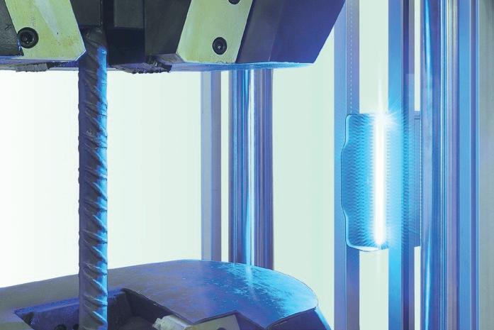
s mentioned in the previous article, the testing of materials has to be performed with machines and equipment that ensure high-quality – using cutting edge technology. Such testing machines apply increasing stress to the material under test until it fails, simultaneously measuring the applied force and, depending on the type of test, other physical properties.
A prime example are tensile testing machines, with the UNI EN ISO 6892 standard providing two different methods for performing tensile tests on metallic materials at room temperature: Method A and Method B.
Method A is normally used to reduce test speed variations in the determination phase of parameters sensitive to the test speed itself. This method can reduce uncertainties in test results. Furthermore, Method A has two declinations:
A1 = speed control is based on extensometer measurement.
A2 = speed control is based on the crosshead separation of the testing machine.
The A1 method eliminates the influence of the testing machine compliance and should allow the strain rate to be controlled very precisely. However, in the case of serrated yielding, it would not be possible to control the strain rate. In these specific cases, the A2 method is advisable.
It is important not to introduce discontinuities in the stress/strain curve, so as not to distort the test results. Therefore, any change in speed must be applied gradually without jerking, because speed influences the result and this must always be taken into account.
Method B foresees the application of load control up to the yielding, at which point it is impossible to control the loading rate, and then switching to strain control as described in Method A2. The B method, by its very nature, can introduce distortions into the graph and therefore should not be used when determining the parameters precisely at the change of control.
The standard states what the speeds must be for each phase of the test, for both Method A and Method B: ‘The loading rate range is between 2 Mpa/s and 60 Mpa/s, while the strain rate range is, depending on the test phase, between 0.00007 and 0.008 in s-1. It is important to point out that the speed, once set, must be kept stable and constant.’
In conclusion, which speed should be applied and which method should be used between A and B? The answer is given by the standard EN 6892-1, which states that it is at the discretion of the producer or the test laboratory – provided that the method applied meets the reference standard requirements.
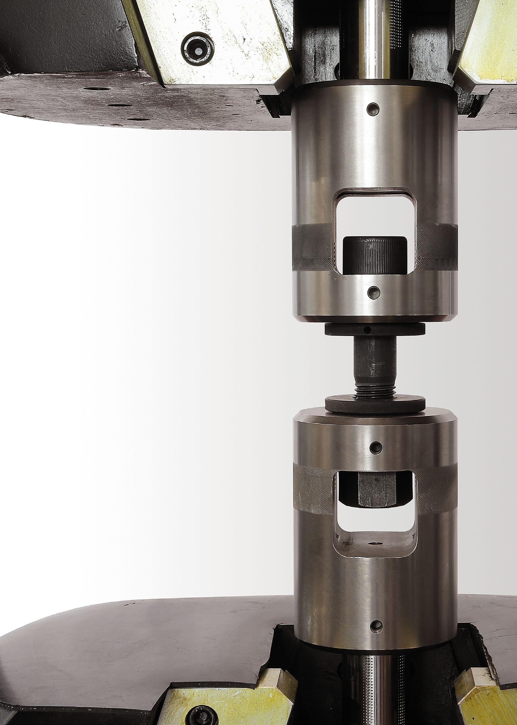
The tensile testing machines produced by CERMAC are technologically advanced and allow the best performance in terms of test precision and control. These machines are able to apply both Method A and Method B, in compliance with the speed ranges requested by the standard.
Through a 1kHz PID control algorithm and 24-bit measurement resolution, maximum control accuracy is also ensured by obtaining the highest accuracy of test speed, avoiding any discontinuity that could affect the results. This is possible with both electromechanically and electro-hydraulically controlled machines. In this case, digital servo valves and double acting actuators units are used. CERMAC machines also comply with the requirements of the relevant reference standards.
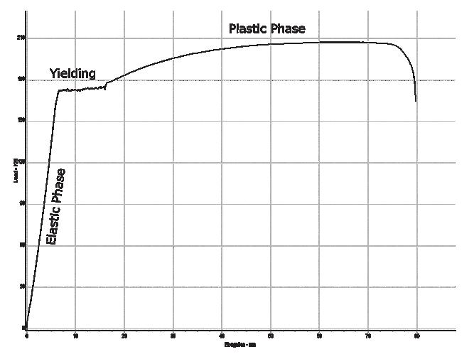
Stress/strain diagram of a tensile test
210
180
150
Load - KN 120
90
60
30
0 10 20 30 40 50 60 70 80
The role of extensometers
By Alan Thomas, marketing department, ZwickRoell Ltd
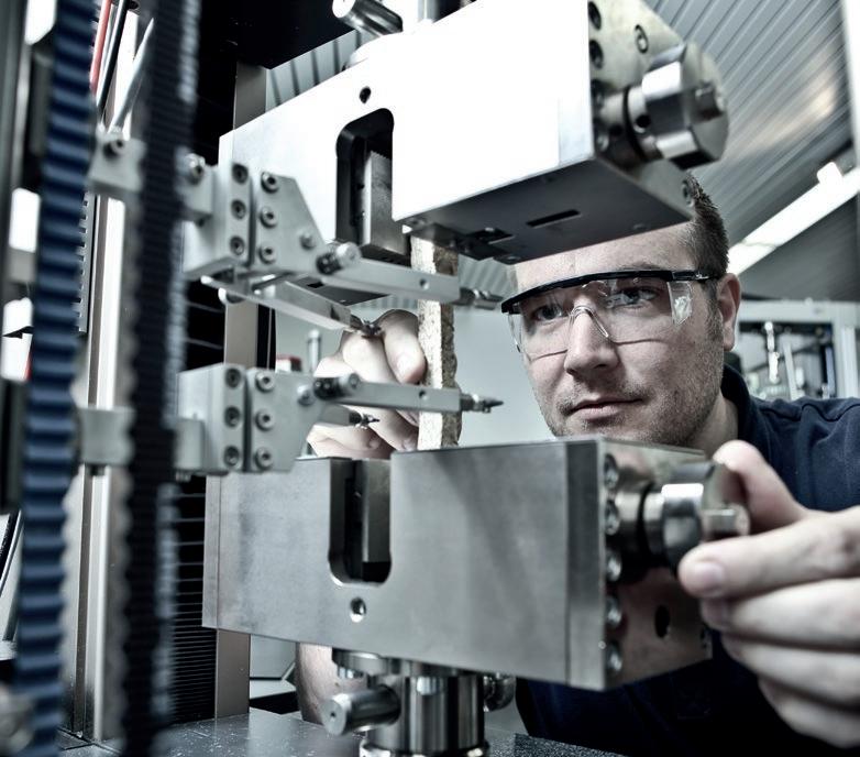
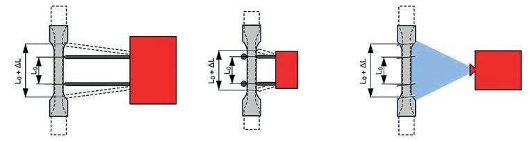
Strain measurement devices play a key role in the testing of a variety of materials, with one such item being the extensometer – a strain measuring device that can be used to measure the extension of a test specimen under load.
T
he extension of a material is a physical deformation that occurs when it is subjected to a load such as the pulling force associated with tensile testing. In addition to strain caused by tensile loads, extensometers also help determine compressive deformation or deflection under different types of load applications, including cyclic tests, compression tests and flexure tests.
Extensometers measure strain directly on the specimen. This eliminates measurement influences from other testing components and increases accuracy. Strain measurement is required in the determination of characteristic values of a material. The tensile modulus, Young’s modulus, yield point, strain at break, r-value, and Poisson’s ratio, are typical values determined with an extensometer. This information is essential when comparing materials and helps manufacturers determine whether they can withstand the loads to which they are subjected when used for their intended purpose.
Extensometers can be used in a wide variety of industries and an even wider range of materials. Examples include metals, plastics, fibre-reinforced composites, elastomers, films, textiles, ropes, paper and wood.
Types and categories of extensometers
To understand how an extensometer works, it is important to know that there are essentially two types of extensometers – contact and non-contact or optical extensometers.
Contact extensometers can be further categorised into clip-on and sensor arm extensometers. Non-contact optical extensometers include video and laser-based instruments.
Sensor arm extensometers are attached directly to the specimen via knife edges mounted on the sensor arms. Strain is measured through evaluation of the change in angle or travel distance of the sensor arms. Sensor arm extensometer technology is proven and easy to understand. They are known for providing a high level of modularity, offering flexibility for different test tasks and adaptability from a manual to a fully automated system.
Clip-on extensometers are a cost-effective solution for standard test tasks with low specimen throughput. They are directly attached to the specimen. The measurement value transmission from the specimen to the sensor is short and stiff, by which a high level of accuracy is attained. These extensometers, however, lack in flexibility; from a design perspective, most of them have a set initial gauge length and a short travel distance.
Optical extensometers are camera-based and therefore measure without making contact. Markings on the specimen identify the initial gauge length, either by being placed directly on the specimen or via virtual gauge marks applied with the use of software. The gauge marks are tracked by an image-to-image comparison throughout the test and the travel distance or strain measurement is recorded. Since the camera captures a large part of the specimen, additional evaluation options are available, including 2D DIC (digital image correlation), measurements on several measuring points or automatic determination of the break location, which prevents specimen rejection.
Optical extensometers (video extensometers and laser extensometers) measure without contact and therefore have no influence on the determination of the characteristic values of a material. An additional advantage provided by strain measurement devices featuring non-contact measurement is that they can be used right up to break without risk of damage, even with specimens that are critical in this respect.
A Sensor arm extensometer
Sensor arm extensometer Clip-on extensometer Optical extensometer
(Below: Video extensometer)
Choosing the right extensometer
In materials and component testing the range of applications where extensometers are used is extremely diverse. As a result, the technical requirements for these devices are many and varied, which means that there is rarely a single device that satisfies all needs. The requirements for an extensometer are determined primarily by the characteristics of the material to be tested. This includes its shape and dimensions, test requirements and the formal standards that must be met. These define the gauge length, accuracy, test sequence, and environmental conditions – such as test temperature.
Having said this, the right choice of extensometer cannot be limited to the basic material characteristics such as specimen
dimensions, stiffness, strength and plasticity alone. It is also necessary to decide whether an extensometer can be connected directly to the specimen without influencing the load measurement or mechanically damaging the specimen itself. Very thin specimens such as foils can be sensitive to clamping forces, whilst very small wire specimens do not provide enough visible area for reliable noncontact measurements.
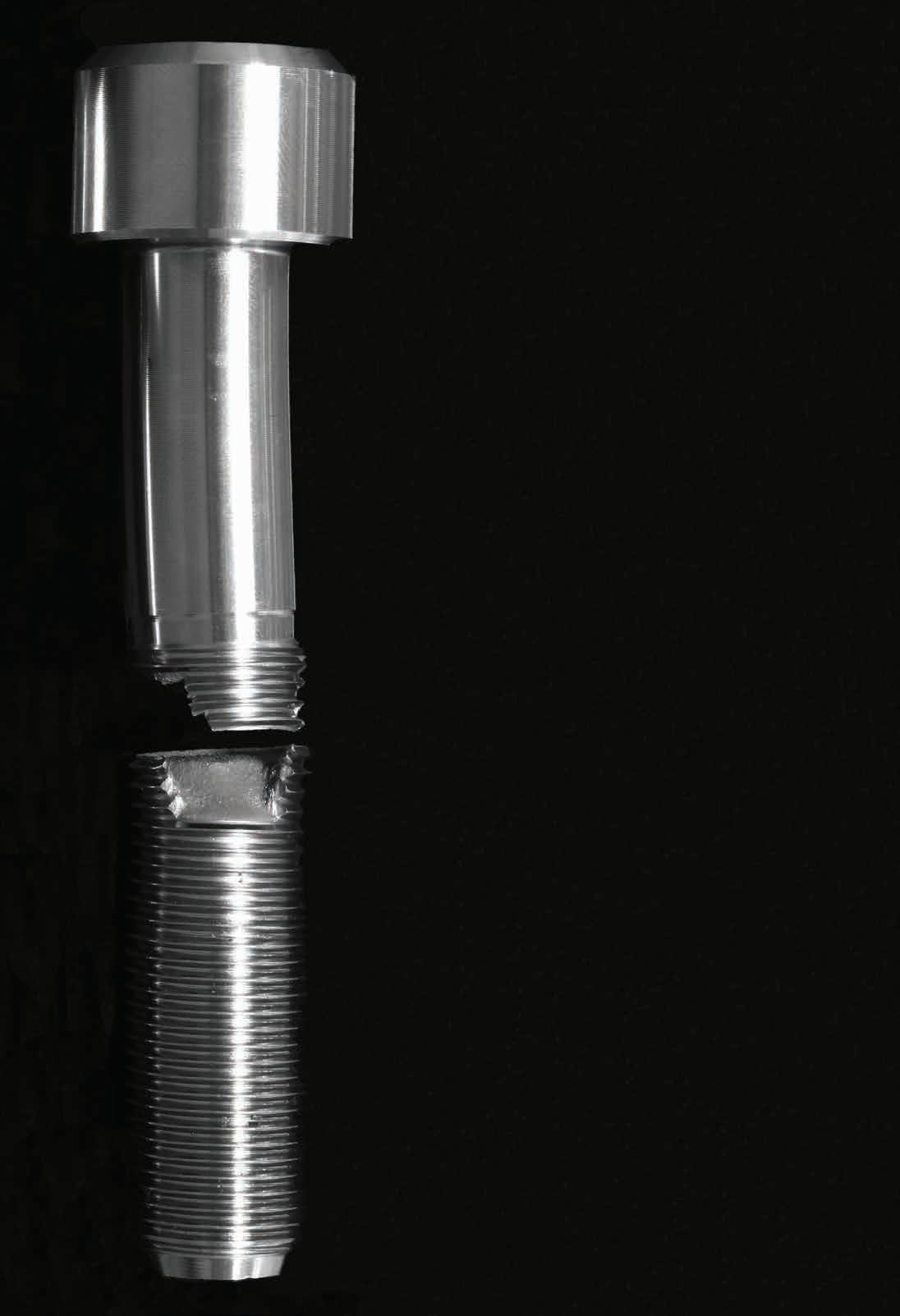
A high stiffness in the initial extension range, followed by high plasticity, traditionally requires more than one extensometer. The first measures small strains (typically up to 5mm) very accurately in the elastic range, and the second measures very high values (typically 500mm). Specimens with very smooth, reflective surfaces, or made of transparent materials are not suitable for non-contact measurement without first fixing measuring marks onto the surface of the specimen. One very important consideration is the behaviour when the specimen fails. Metals and hard plastics will slip through the knife edges of a contact extensometer without damaging them, while swivelling knife edges will further reduce the risk of damage, even if the surface of the specimen is particularly rough.
Almost all tensile testing standards such as ASTM and ISO require strain measurement. The best suited extensometer for an application depends on the requirements specified by the standard, as well as the material properties of the test specimen.
Determination of the ideal extensometer is based on six main criteria. These include properties that must be met, such as extensometer accuracy, resolution, measurement range, required measured values and the test temperature at which the extensometer will be used. However, the key added value is provided by features such as easy handling, reduced learning curve, the scope of functionality and cost per test.
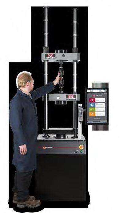
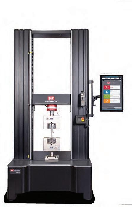
Instron’s Industrial Series and New 6800 Series universal testing systems provide SUPERIOR FRAME STIFFNESS and the DURABILITY needed for testing a broad range of fasteners.

Easy access to measurement technology
Kistler has unveiled its newly overhauled website, which now gives easy access to the most suitable product solution for a huge range of applications. Initially, customers from Germany can also order measurement technology products online in a new web shop, with international customers set to follow
K
istler offers measurement technology for a wide range of user groups and applications, from single sensors to complete measurement solutions. Potential applications include quality assurance in production, weight control of trucks and aerospace testing. Kistler’s focus on the user-friendliness of the new website makes it easy to locate the right product in its extensive portfolio. Users from different industries and sectors can quickly find the product category relevant to them via the ‘Industries and Applications’ tab. Illustrations and videos make complex measurement solutions easy to understand and suitable equipment for any application easy to find. Using the filter function, the product range can be narrowed down to the most relevant options. 3D models, data sheets and operating instructions further facilitate product selection.
Pilot phase of web shop started
Kistler’s large product selection is now available online for the first time via the redesigned website – with a pilot phase initially just in Germany. This means German customers can order standard sensors and corresponding accessories directly by logging into the ‘myKistler’ user area. Products requiring further advice, such as
custom-made items, can also be added to the virtual shopping basket. The checkout function then sends the request to the relevant experts at Kistler, who will get in Hall 1, Stand 804 touch straight away. “It is important to us that we offer easy access to our products to customers from all over the world, from different industries and with a different knowledge of measurement technology,” says David Stucki, head of E-Business at Kistler and responsible for the launch of the new website. “This is why we have adapted the site to local needs in some regions. Users will, for example, primarily see references from their own country of residence,” adds Christoph Keller, corporate program and project manager at Kistler. While online shopping is initially only possible in Germany, preselecting products via the shopping basket is available worldwide. The sale is then concluded with the help of Kistler employees. Step by step, Kistler is set to make the other functions of the web store available worldwide. “Experienced experts, who work very closely with our customers, continue to be an important part of Kistler’s success. With the launch of the new website and the ‘myKistler’ customer portal, we want to provide our customers and our team with a powerful tool that allows quick access to relevant information such as prices, availability and order history,” mentions David Stucki.
Streamlining the measurement of safety and performance critical components
Addmore Engineering, a family business that supplies CNC turned and milled components, believes it has found the perfect way to measure safety and performance critical products with an air gauging system from Bowers Group.
A
s part of its inspection process, Addmore Engineering need to measure bolts, which are critical components on braking systems. It is, therefore, imperative that 100% of the parts produced are within tolerance. The air gauging system from Bowers Group ensures that the performance critical parts, satisfy customers’ requirements to 100% inspect safety critical characteristics and meet tight tolerances.
“The Bowers air gauging system is the perfect solution for us because it standardises the measurement process and eliminates the potential for human error,” states Ben Vasquez, managing director at Addmore Engineering Ltd. “The system allows multiple operators to accurately check the diameter of the components in minimal time, and the modern control panel gives a quick yes/no output that allows each bolt to be checked with guaranteed high precision results in a matter of seconds.”
Addmore Engineering manufactures in excess of 10,000 of the bolts every month, therefore a fast, repeatable, and user-friendly solution was key. The business had previously experienced some difficulties whereby operators were achieving differing readings with micrometers; a significant problem when trying to measure 7-micron tolerances. The Bowers air gauging system enabled many members of the team to check component diameters in a short space of time, and the touchscreen display – with its customisable display interface – is easy to read and interpret results. The air gauging system uses air flow volumes and pressures to measure parts and is well suited for applications that demand sub-micron precision tolerancing.
The air gauging technology also enables the measurement of not only dimensions, but geometric and relational characteristics, such as squareness, parallelism, ovality, taper and straightness. “Personally, I have always been aware of the benefits of air gauging. During my apprenticeship I regularly used the older dial/clockbased systems. The advantage of the modern digital display is that anybody can see if the component is correct just by looking at the colour,” adds Ben. “The sales and technical support from Bowers has also been first class and we have already begun discussions about further projects.”
