TECHNICAL
How to properly pin a shaft and hub assembly By Christie L. Jones, market development manager at SPIROL International Corporation
T
One of the primary benefits of using a coiled spring pin to affix a hub or gear to a shaft is the coiled pin’s ability to prevent hole damage. Another benefit is that the coiled pin absorbs wider hole tolerances than any other press-fit pin. This translates to lower total manufacturing costs of the assembly. here are a few design guidelines that must be adhered to in order to achieve the maximum strength of the pinned system and prevent damage to the assembly. The design guidelines can be divided into two groups: The shaft and hub, and the pin.
1. Shaft and hub considerations
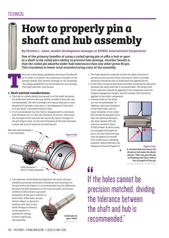
The hole in a shaft should not exceed 1/3 of the shaft diameter. For mild steel and non-ferrous shafts, standard duty pins are recommended. The extra strength of a heavy-duty pin is only beneficial if the hole is less than 1/4 the diameter of the shaft or if the shaft is hardened (Figure One). It is recommended that the hub be designed with a minimum wall thickness of 1.5 times the diameter of the pin. Otherwise, the strength of the hub will not match the shear strength of the pin (Figure One). As the wall thickness of the hub increases, so does the area of material around the pin.
Min hub wall thickness = 1.5 pin diameter
Figure One
The hole should be centered in both the shaft and hub to prevent stress concentration and ensure there is enough material around the pin to withstand the applied forces. If the holes cannot be precision matched, dividing the tolerance between the shaft and hub is recommended. The larger half of the tolerance should be applied to the component with the longest engagement length, and the smaller half should be applied to the other component. Countersinks on the holes are not recommended. In addition, the outer diameter of the shaft (OD) and the inner diameter of the collar (ID) should be designed such that the distance between the shear planes (OD-ID) does not exceed 0.13mm (0.005 inches). In both cases, an unsupported length of pin in an area where torque may be applied is created. This could cause a bending moment, which shortens the lifespan of the pin (Figure 2). Figure Two: A countersink increases the distance between the shear planes. This can put the pin in bending and thus reduce the strength of the pin
Hole diameter = Max 1/3 shaft diameter
The diameter of the holes through both the shaft and hub should be precision matched to eliminate any movement of the pin within the holes. It is recommended that the difference between the hole diameters in the hub and shaft not exceed 0.05mm (0.002 inches) to prevent movement of the parts relative to each other. Otherwise, the pin will be subject to dynamic loading such that a very small change in velocity could equate to a significant change Coiled pin in in force impacting gear shaft the assembly.
148 FASTENER + FIXING MAGAZINE // ISSUE 111 MAY 2018
If the holes cannot be precision matched, dividing the tolerance between the shaft and hub is recommended.�