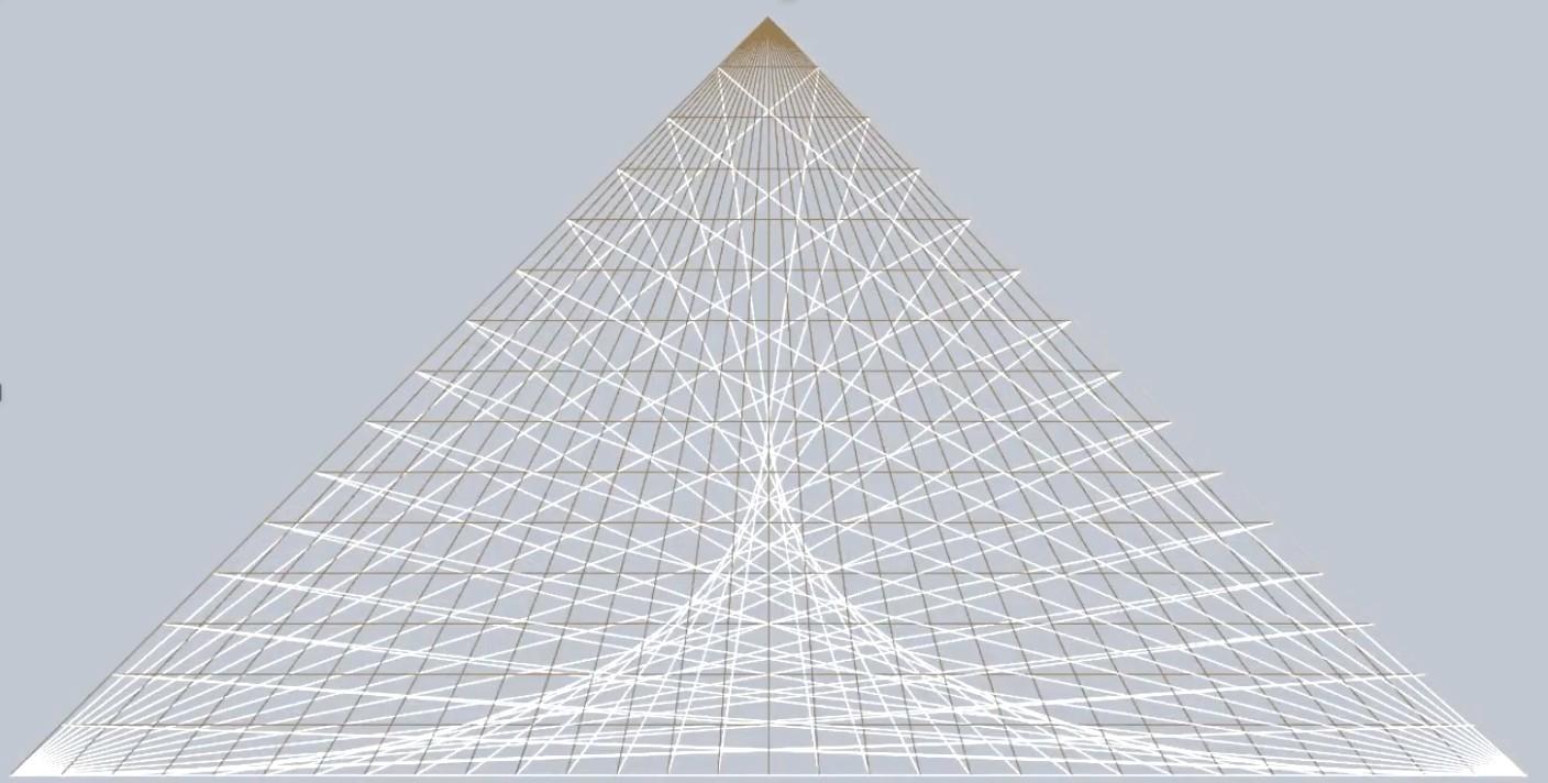
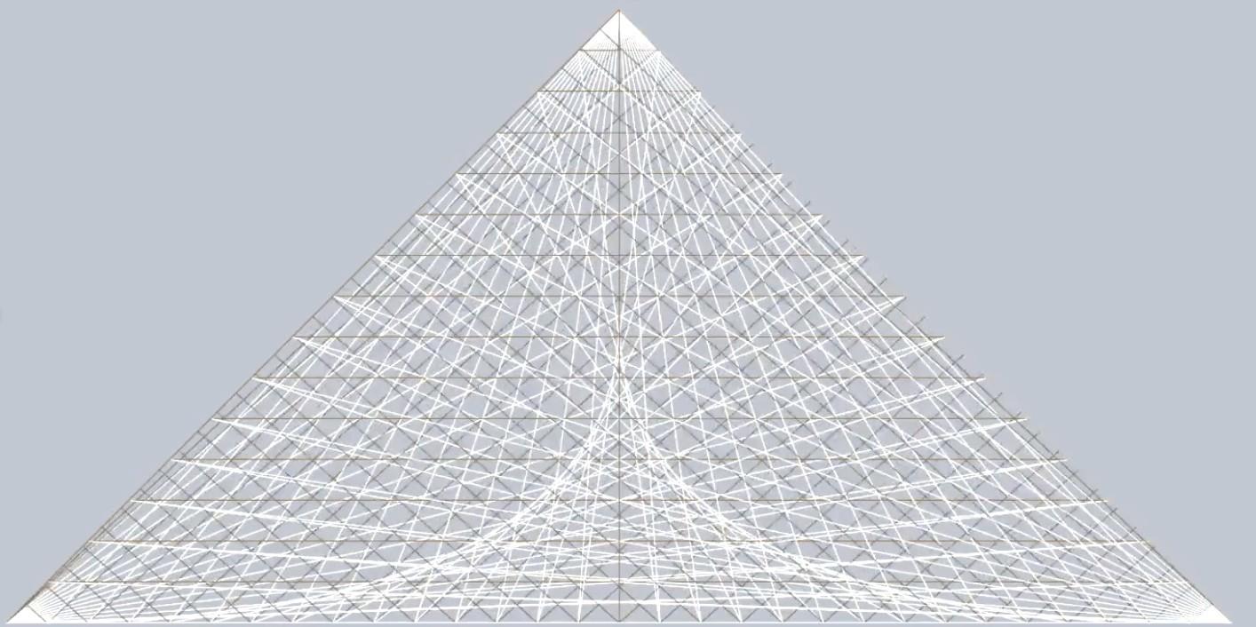
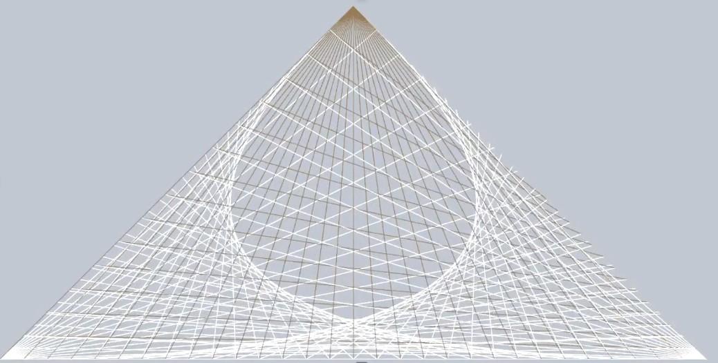
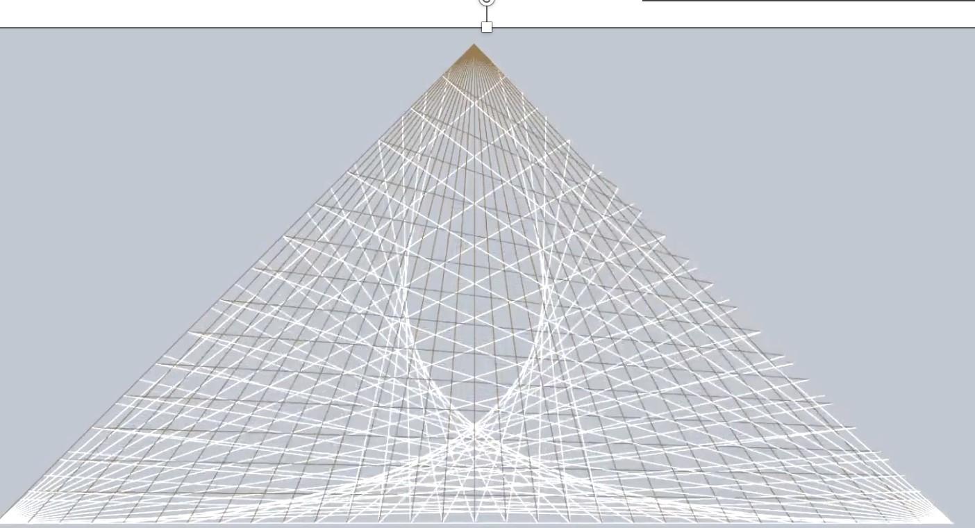
Sunlight controlling adaptive façade for office building
F.I.D.I.T.I Facade:
Sunlight controlling adaptive façade for office building
Abstract. This paper introduces The F.I.D.I.T.I. Façade system, an Innovative envelope designed with Diamond shape to enhance thermal comfort by integrating Illuminance through Toggleable elements on an Island site. The modular Façade system is visually striking and energy-efficient, with Illuminance, an adaptive lighting and shading. Geometric precision and structural stability are symbolized by Diamond with Kish Island in Iran as the real-world test site, providing diverse environmental conditions for evaluation. Toggleable elements allow the façade to adapt to changing conditions and user needs, enhancing energy efficiency and comfort. Innovation drives the continuous integration of cutting-edge technologies, ensuring the F.I.D.I.T.I. façade meets modern urban demands. This paper discusses the design concept, process and digital and mechanical output of one module of entire façade with results and analysis exploring the theoretical underpinnings and practical applications of F.I.D.I.T.I facade, emphasizing its potential to transform facade architecture towards sustainability and resilience. This research aims to utilize the distinctive features of sensor and actuator integration to propel progress in sustainable building design and construction. The study aspires to advance the development of innovative, energy-efficient façade solutions for both new constructions and existing buildings, fostering the future of sustainable architecture.
Keywords. Adaptive Façade, Illuminance, Solar Radiation Sensor, sustainability, energy efficiency.
1 Introduction
Dynamic façades are vital due to their ability to reprogram logic flexibly according to anticipated future conditions. They can adapt to potential alterations in the site context and surrounding environment. Research into dynamic façades and shading solutions has seen significant growth. Unlike static and manually controlled devices, these systems adaptively respond to continuous climate and weather variations, enhancing daylight availability and visual comfort in interior spaces. [1] The objective of the project is to design an innovative façade system that seamlessly integrates roller blinds into the façade system, emphasizing sustainability, userfriendliness, and cost-effectiveness with shading. This approach aims to enhance the functionality and aesthetic appeal of building exteriors, making it a viable solution for a wide range of structures.
Integrating roller blinds into a building facade presents a sophisticated approach to enhancing both the functional and aesthetic qualities of modern architecture. This seamless incorporation not only improves energy efficiency by controlling solar gain and thermal performance but also contributes to the overall design, providing a sleek and contemporary look. This holistic integration underscores the growing importance of adaptive architectural elements in creating comfortable, energy-efficient, and visually appealing living and working spaces.
The subsequent section details the concept behind the facade system, the reference study and the location of the site which is considered for the experiment of the façade system.
1.1 Design Concept
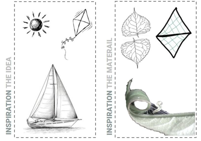
The design concept of the F.I.D.I.T.I. adaptive façade system is deeply rooted in the environmental and cultural context of southern Iran, particularly the region overlooking the Persian Gulf. The design draws inspiration from two main sources: the local tradition of kite flying and the natural efficiency of silkworms in producing silk. These elements were chosen to create a system that is both functional and aesthetically pleasing, reflecting the rich cultural heritage and natural phenomena of the area, The sight of numerous sailboats and children flying kites is a common and culturally significant activity in southern Iran, symbolizing luck and deeprooted traditions.
Additionally, the silkworm's silk production process serves as a bio-inspiration for the shading system. Just as silkworms spin silk threads to create protective cocoons, the I-mesh fabric and rolling mechanism of the façade emulate this natural process. This biomimetic approach ensures that the system is efficient, durable, and capable of providing optimal shading and light control.
1.2 Case Study
Figure 1: Conceptual Sketches of inspiration of the Façade design.
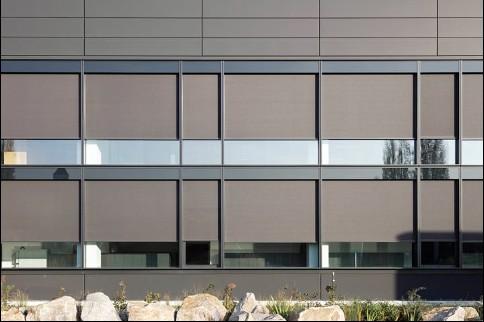
The Schüco plant 4 building in Germany is an excellent example representing a fully integrated textile sun shading system within building facade. This system features a textile blind that operates along narrow guide tracks, seamlessly integrated into the facade's load-bearing structure. The integrated zip technology and the textile fabric used for sun shading, highlighting their role in enhancing the system's functionality and design. [2]
In conclusion, leveraging insights from the Schüco plant 4 building as a foundational case study, the integration of a shading system into a facade is strategically designed to achieve the objective of the research.
1.3 Site Selection and Analysis
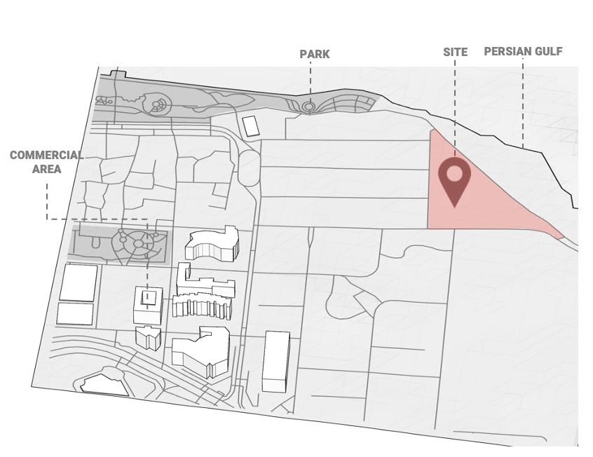
The F.I.D.I.T.I. project is considered in Kish, Hormozgan, Iran, characterizing by its strategic orientation facing north towards the sea, which optimizes natural lighting throughout the day and provides picturesque views of the Persian Gulf. The region's climate features high humidity, influenced by its coastal proximity to the Persian Gulf, and experiences consistently high temperatures year-round. With summer temperatures ranging from 24°C to 42°C and winter temperatures from 13°C to 31°C, effective shading control is essential for maintaining comfortable indoor conditions.[3] The project covers an area of 385 m2 and aims to integrate innovative facade solutions that enhance energy efficiency, mitigate solar heat gain, and harmonize with the hot and humid climate of the region.
Figure 2: Textile Sun Shading Façade of Schuco plant 4
2 Materials and Methods
This segment offers an overview of the software and hardware aspects of the project, presenting in-depth analysis of the various components, resources, and the procedures involved in developing the ultimate digital and physical prototypes.
2.1 Project overview
The F.I.D.I.T.I. façade is an innovative design proposed for a building in Kish, Hormozgan, Iran. This location is known for its extreme climate, which presents both challenges and opportunities for architectural innovation. The F.I.D.I.T.I. façade aims to address these challenges by integrating materials and technologies to improve energy efficiency and comfort.
Figure 3: Location of site.
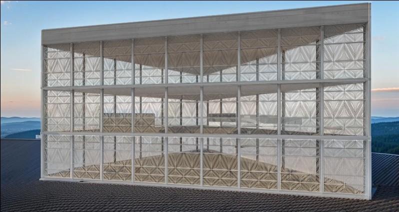
Figure 4: 3D View of Building with F.I.D.I.T.I. Facade.
Key characteristics of system design include:
Sun protection
Quick construction: Easy assembly on-site
Lightweight: To minimize the overall weight of the building.
Stability: Ensuring safety and durability.
Adaptability: Designed to adapt to varied temperatures.
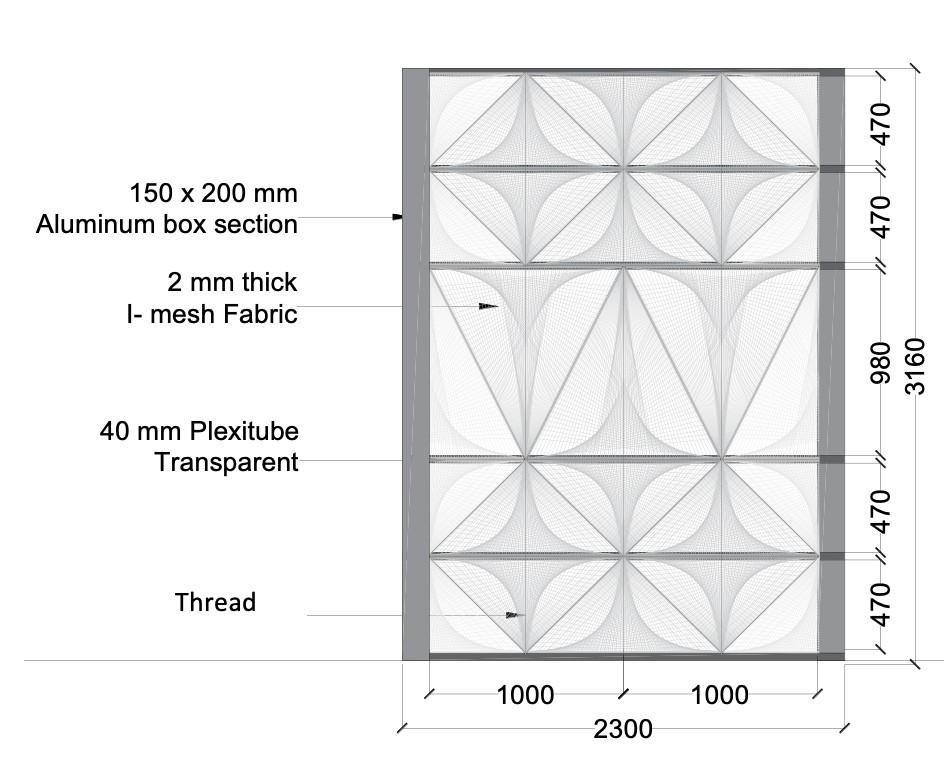
The F.I.D.I.T.I. Façade is meticulously designed for a three-story building, with each floor encompassing an area of 130 square meters. The size of the panels is determined by the height of each floor and the specifications of the curtain wall system. To ensure stability and secure installation, vertical mullions are employed to support the attachment of these panels. Each panel measures 2.3 meters by 3.16 meters and is horizontally divided into three sections.
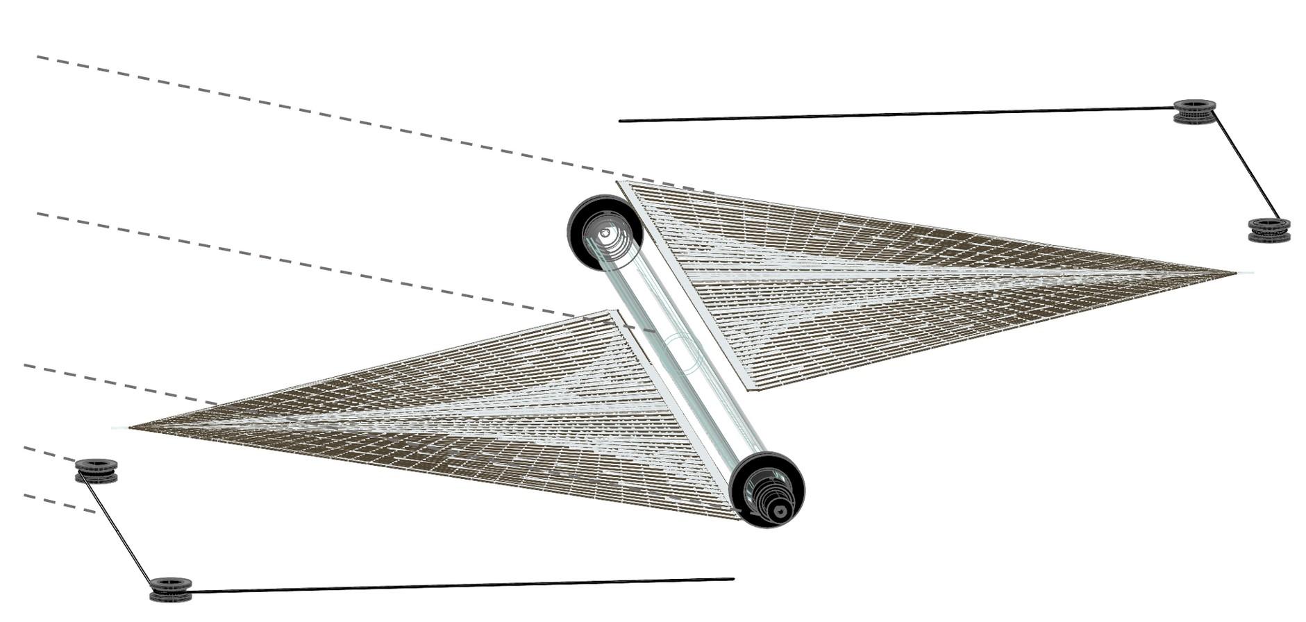
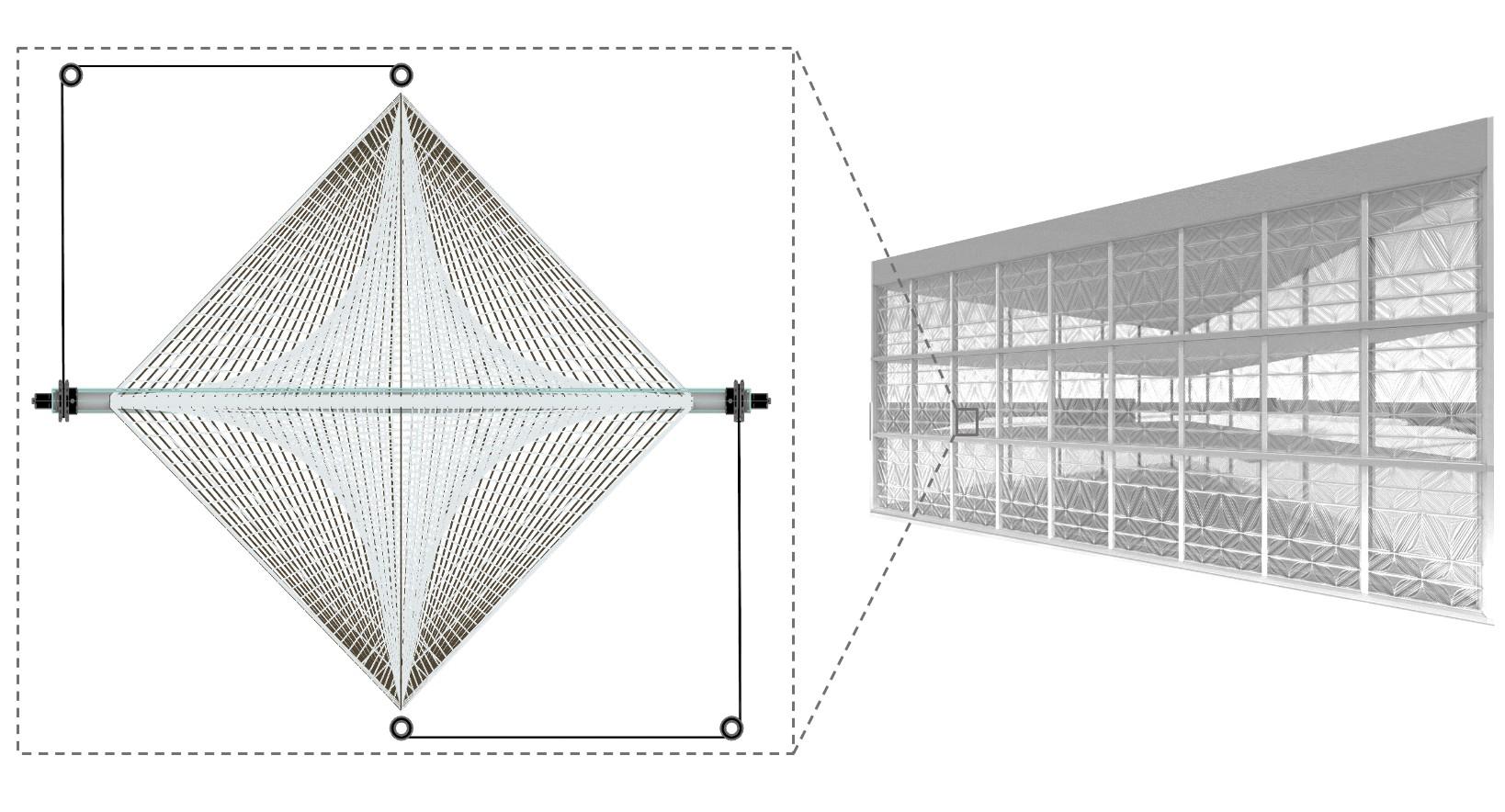
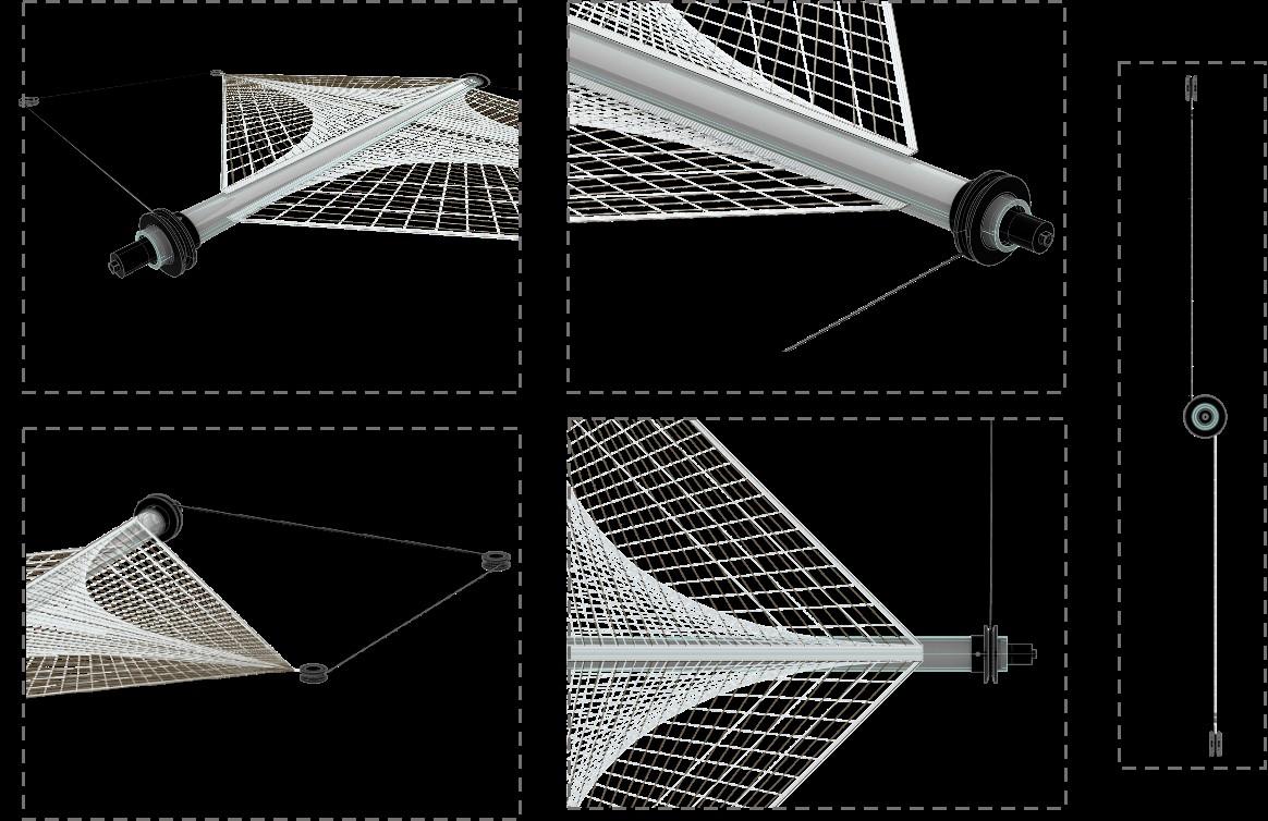
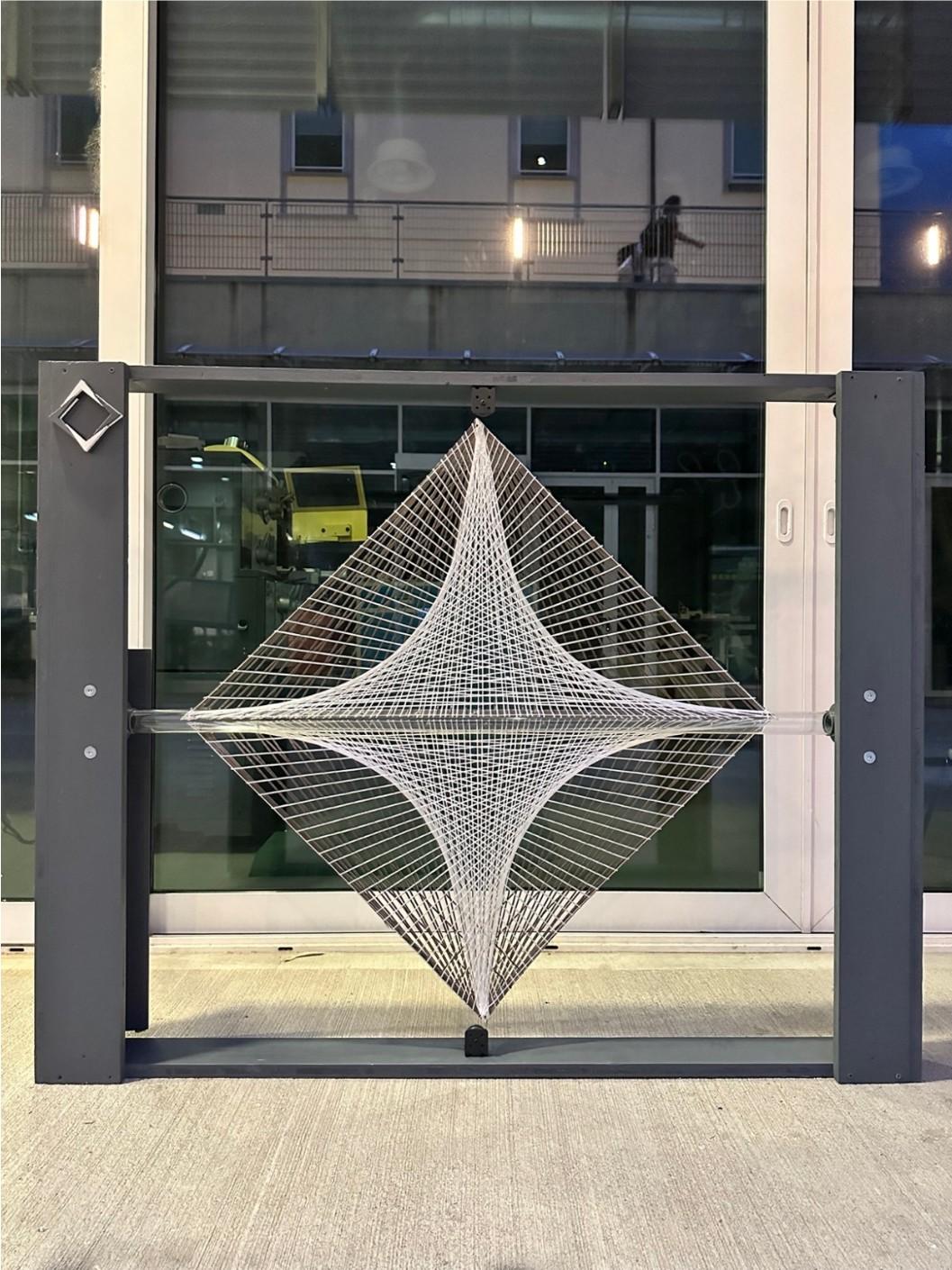
In terms of functionality, each panel is equipped with five shafts, enabling the fabric to rotate around the shafts with the assistance of motors attached to each individual shaft. This design allows for precise control of the shading and light entering the building. Notably, the middle section of each panel is designed to align with the human eye level, ensuring an unobstructed view by avoiding interference from the horizontal divisions. This thoughtful arrangement enhances both the aesthetic appeal and practical functionality of the façade, creating a harmonious balance between design and usability. Fig. 5 showcases the geometry of panel and its elements.
Figure 5: Panel Detail drawing
2.2 Elements of module
This section outlines the materials and methods employed in the construction of the adaptive façade prototype. The selection of materials was based on their functional properties, aesthetic appeal, and overall contribution to the structural integrity and efficiency of the design. The methods applied ensure precision, durability, and adaptability to the environmental conditions at the project site.
The selection of these materials is driven by the need for durability, functionality, and aesthetic appeal. Each component has been chosen to ensure the adaptive facade prototype performs efficiently under various environmental conditions while maintaining a modern design. The technical specifications provided ensure that the materials meet the required standards for performance and longevity, making them suitable for real-world applications.
Figure 6: Elevation of the Facade
Figure 7: Elements of module.
a. Fabric
a.1. Concept of designing the fabric
The idea behind designing the I-mesh fabric is to combine traditional design elements with modern materials. The diamond-shaped pattern was inspired by local cultural motifs and refined through several versions. This design ensures the fabric is both strong and visually pleasing, making it suitable for withstanding environmental challenges while fitting well with the overall architectural style.
a.2. Material of fabric and company
The I-mesh fabric has two layers: the first layer is made of basalt fiber, which is 2.2 mm thick, and the second layer is made of glass fiber, which is 1.7 mm thick. Basalt fiber provides excellent strength and durability, making it perfect for the structural part of the fabric. Glass fiber is resistant to sunlight and heat, making it ideal for outdoor use. These materials are sourced from top companies known for their high-quality composite materials, ensuring the fabric's long-lasting performance.
Below, you can find the fiber properties and I-Mesh technology data.
a.3. How fabric is attached to the shaft
The I-mesh fabric is attached to the shaft using a special mounting system. The edges of the fabric are reinforced to prevent fraying and ensure a snug fit. The fabric is then secured to the shaft with brackets and clamps that evenly spread the tension across the fabric. This keeps the fabric tight and stable, providing effective shading while withstanding various weather conditions. The attachment system is also adjustable, allowing for precise alignment and tensioning during installation.
Figure 8: Basalt fiber (Left) and Glass fiber (Right)
Table 1: Fiber Properties.
Table 2: I-Mesh Technology.
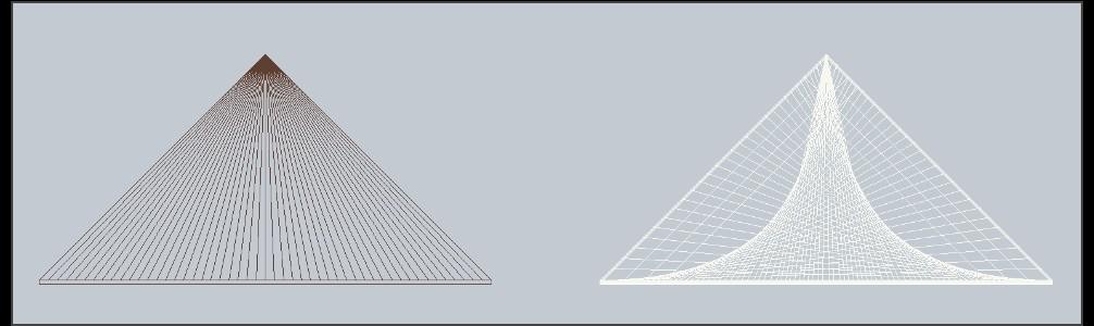
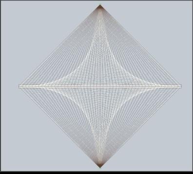
Several different patterns were considered during the revision process. After evaluating all of them, we selected the one shown above as the final design due to its optimal shading level and required resistance. Additionally, this pattern allows the fabric to be rolled around the shaft efficiently.
Figure 9: Final Pattern of I-mesh in facade system.
Figure 10: The process of the design of the pattern.
b. Shaft
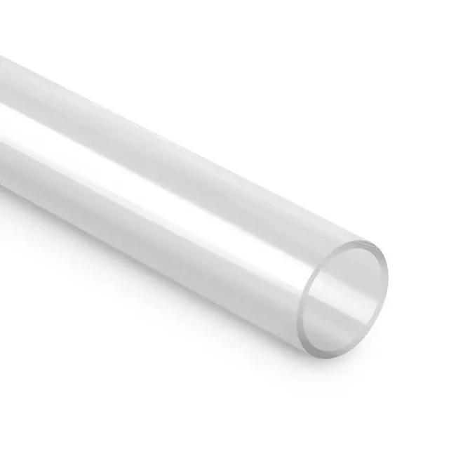
The shafts utilized in the F.I.D.I.T.I. Façade system are constructed from transparent Plexi tubes, specifically composed of polymethyl methacrylate (PMMA). These shafts measure 40 mm in external diameter and 36 mm in internal diameter, with a length of 1200 mm. Each shaft is meticulously designed to facilitate the rotation of fabric within the facade system, contributing to the overall functionality and aesthetic appeal of the structure. The transparency of the Plexi tubes ensures minimal visual obstruction, maintaining the sleek, modern look of the facade. These PMMA shafts are lightweight, with a net weight of only 0.66 kg, making them easy to handle and install.
Figure 11: Plexi tube transparent 40/36x 2000mm
The choice of PMMA as the material for the shafts offers several advantages, including excellent optical clarity, durability, and resistance to environmental factors. These characteristics make PMMA an ideal material for the dynamic and visually demanding requirements of the facade system.
c. Bearing
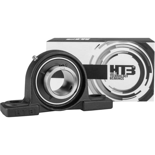
High-technology bearings (HTB) are used for the connection of the shaft to the frame to ensure smooth and efficient operation of its components. Specifically, the facade utilizes GOPART UCP 204 bearings, known for their reliability and precision. These bearings feature a self-aligning mechanism that accommodates slight misalignments, ensuring optimal performance and longevity of the system.
Constructed from durable cast iron, the GOPART UCP 204 bearings provide robust support and resistance to wear and tear, essential for the demanding conditions of an architectural facade. Each bearing unit includes a
bracket with a diameter of 20 mm, designed to seamlessly integrate into the structural elements of the facade. The cast iron material enhances the bearing's strength and stability, making it suitable for high-load applications and ensuring the smooth rotation of the facade's moving parts.
d. Ball Bearing
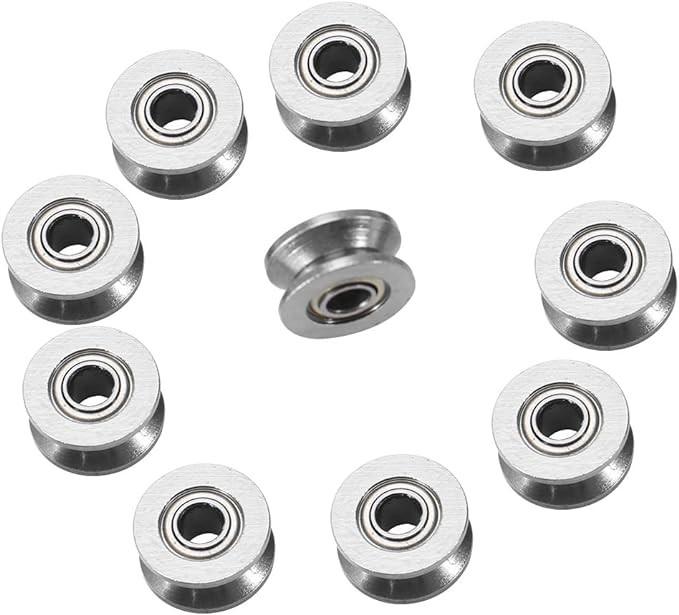
The deep groove ball bearing, model V624ZZ, are precision-engineered components designed for smooth and efficient rotational motion. Manufactured by WALFRONT, these bearings are made from high-quality carbon steel, ensuring durability and resistance to wear. The bearings feature an internal diameter of 4mm, an external diameter of 13mm, and a thickness of 6mm, making them suitable for various mechanical applications. Despite their robust construction, each bearing weighs only 30 grams, which facilitates ease of use and integration into machinery. These specifications make the V624ZZ model ideal for applications requiring reliable performance in demanding conditions.
e. Thread
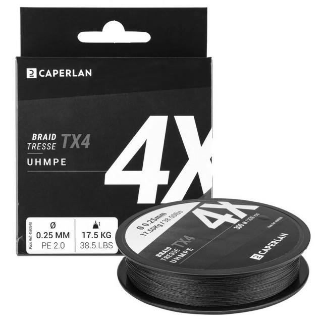
The F.I.D.I.T.I. Façade system utilizes braided fishing lures, specifically the TX4 model, which are constructed from 4 mass-dyed UHMWPE (Ultra-High Molecular Weight Polyethylene) fibres. These fibers are known for their exceptional strength and durability, ensuring long-lasting colour retention even under harsh environmental conditions. The material used is polyethylene, a high-performance polymer that provides a balance of strength and flexibility. The TX4 threads offer a resistance of up to 17.5 kg, making them robust enough to withstand significant tension.
Each spool of TX4 thread measures 130 meters in length and has a diameter of 0.25 mm, providing ample material for various applications within the facade system. The threads are lightweight, weighing only 100 grams per spool, yet they deliver remarkable tensile strength. The military green colour of the threads not only enhances their aesthetic appeal but also ensures they blend seamlessly with the facade's overall design.
Figure 13:Deep groove ball bearings
3 Computational design paradigm
3.1 Gear computational design
The study began with initial designs that included computationally designed gears. As the design process progressed, revisions were made, leading to the elimination of some initial designs. The following details the computational aspects of the working of gear.
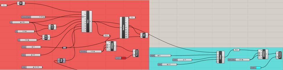
To find the initial design stage, it was decided to use a parametric design, for size variability and full control over the interaction of internal structural elements. To do this, use of Grasshopper in conjunction with modelling inside Rhinoceros must have additional plugins, like Planthopper and Pufferfish. The first addition allows various tools to parameterize the shape of gears while having zero clearance between the main gear and the child gear. Since the initial prototype had the concept of 2 shafts, which separately carried the mesh and the cable that transmitted tension, respectively, the task was also to show the relationship between the movements of internal objects and the direction of rotation of each element.
This part of the “GearsV2” script (object note in the provided source files) includes the use of the “Construct Gear” tool, which introduces variability in the size of the main gear and provides the ability to change its size quickly. Due to the dependency provided in this plugin, the dimensions of the child gear also change in proportion to the main one, which saves time and eliminates the possibility of mismatches in the main moving parts of the structure that are subject to abrasion. For these purposes, this script provides variability in such parameters as number of teeth, tooth width, pressure angle addendum, dedendum and shaft hole. Within these parameters, there are dependencies for standardizing gears, which are followed according to the rules for working with this plugin. When finding a plan view, the gear needs to be given volume by adding thickness, for which the “Offset Mesh” tool from PufferFish was used. Afterwards, to create a child gear, you need to use the output of the main gear in the “Child Gear” tool with the variability of such parameters as connection angle,
Figure
Figure 15: Gear Variability with Grasshopper.
teeth count and shaft hole size. Once the final shape is achieved, it is given a thickness in the same way as the main gear with pufferfish's “Offset Mesh”.
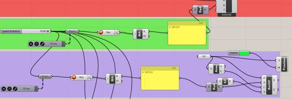
To bring these gears into an animation state, in which you can set their speed and direction, the input variable of the “Construct Gear” tool – Rotation – was used. Initially, it must be used to rotate around its axis manually, however, using the diagram below, you can put them in constant rotation.
The Trigger + Data Recorder combination works here, which allows you to record values with a given interval, the output of which with Mass Addition and Mass Subtraction (or Mass Addition multiplied by -1 to obtain a constant decrease in value) allows you to constantly increase the angle of rotation of the gear around its axis. All moving elements use one number slider, since if there are 2 gears, their gear ratio will be 1:1, which will mean the same rotation speed for each of these elements. Ultimately, all that remains is to set the surface for rotation and set them in motion using “rotate 3d” with the given planes relative to which the rotation will take place.
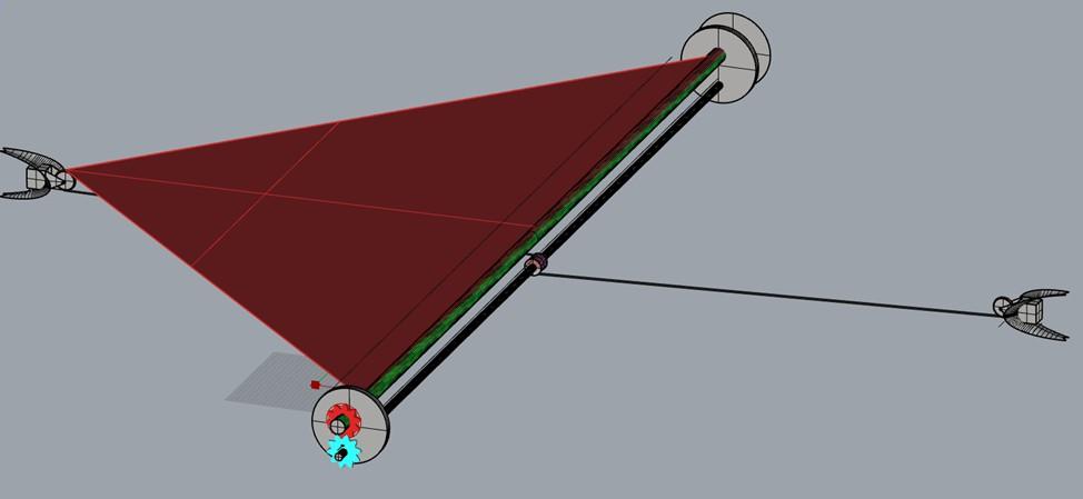
The result, at this stage of the previous concept, offers a rotation of the main elements (the outer gear box and the right side of the mesh are hidden. Availability note for gear motion animation video).
3.2 Animation by Grasshopper
In the chronology of this project, it was possible to use a ready-made solution for a mesh installation, but it was also possible to create it with a unique design and the decision to use computational design allowed us to choose the most balanced version of I-mesh.
Figure 16: Setting the plant in motion using Grasshopper.
Figure 17: Interim summary of installation at the stage of double-shaft module design.
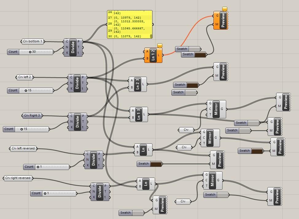
Figure 18: Creating an I-mesh pattern using curve division in Grasshopper.
The use of already known installation dimensions made it possible to have the dimensions of I-mesh taking into account the overlap when attaching the fabric to the shaft from two diametrically opposite sides. These values were transferred in the form of curves to a Rhino, which were divided into a large number of segments using a division curve. Each segment had two material arch points, and they were connected in different variations that could be executed by the I-mesh printing machine. For visual perception, a color swatch was used, which represented basalt and glass fiber. The final result is presented in the attached file (note pattern animation; combination pattern + pattern script).
To animate the opening and closing of the final prototype, rhinoceros model source codes were used, which represented the final product.
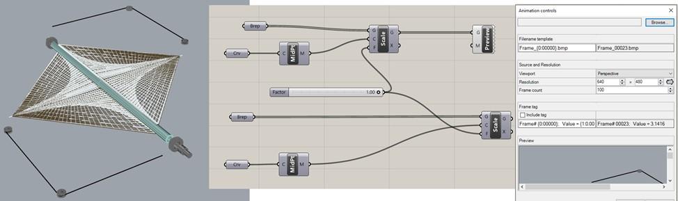
Figure 19: Creating a frame-by-frame animation of the final module with grasshopper.
Using the Scale I function, the mesh can be reduced, which correctly reflects the change in the model when the mesh is wound on a shaft that is set in motion. Number Slider has an animation function in which the scale will be reduced to zero in a given number of frames, which were stitched together and show how a given model behaves in a real prototype and can be used in a product presentation (the final result is presented in the files adaptive + animate; module animation).
4 Result
4.1 Solar analysis
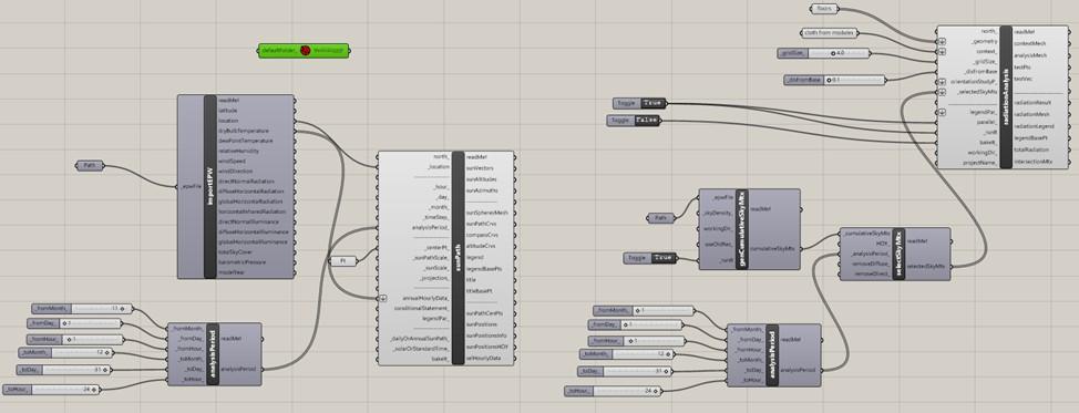
To evaluate the impact of the F.I.D.I.T.I. modules. The radiation analysis method was used, which is made possible using the LadyBug plugin. To do this, it is necessary to model the area next to the building and the building itself along with the modules. To achieve the maximum reduction in radiation analysis, modules will be installed on each part of the facade on all sides. The possibility of using a similar honeybee plugin for illuminance analysis was also considered, however, in this plugin it is necessary to set the window-to-wall ratio value and enable brep of windows when in the case of this analysis the Window to wall ratio was 100%, which represented a completely glazed curtain wall and for making The windows had to be cut from the curtain wall into the shape of the facade systems, which is not the best method. The analysis below shows the dependence of radiance with and without modules at an obvious level.
Figure 20: Ladybug script that allows you to take radiation analysis measurements.
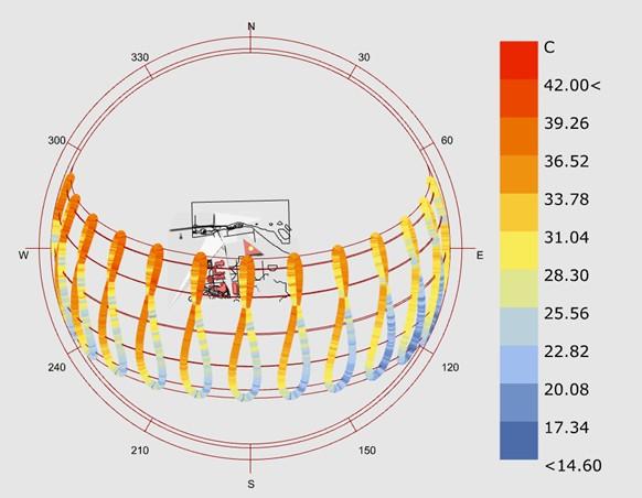
To carry out the analysis, an EPW file with the Kish Island location was connected, which was added using “Import EPW” for annual hourly data analyses, which is available with the “ladybug sunbath” tool, which provides data for a given period, which can be configured with an accuracy of up to an hour in throughout the year. This way you can get the values of annual temperatures, wind speed, direct normal radiation, and so on. Below is an example usage for finding Dry Bulb Temperature.
Figure 21: Example of using annual hourly data in LadyBug.
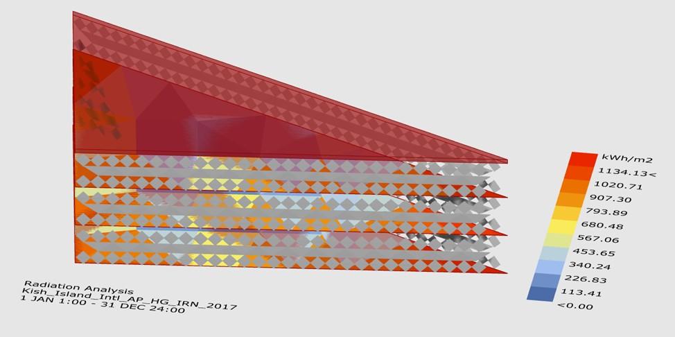
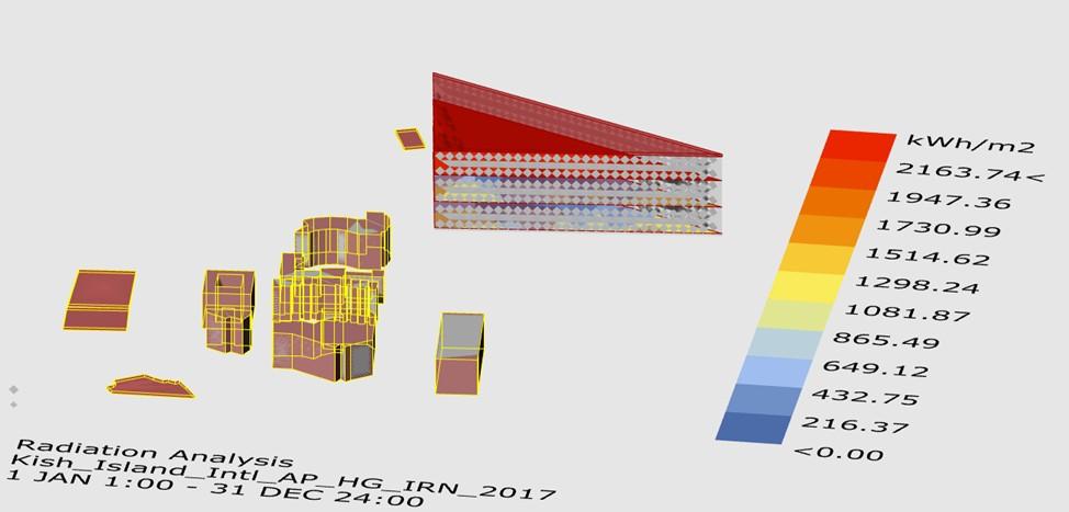
This option is not suitable for analyzing the influence of modules; it serves to obtain holistic values that help to create an overall picture of the climate and the object under study. For a more accurate analysis, the “radiation Analysis” tool was used. For it to work, you need to provide a Cumulative sky matrix, which also uses an EPW file, which, using the “Select Sky Matrix,” can transmit EPW values for a given period with an accuracy of up to an hour for analysis to selected objects. Input values geometry and context directly affect the resulting analysis values, along with setting the visual result with grid size and distance from the facade. All this is brought to work using Boolean toggle on radiation analysis and cumulative sky matrix. The results are presented below, and they show the significant impact of the modules on radiation inside the building.
22: Annual results using a facade system on every wall of a building.
The resulting values show an impact of reducing the maximum radiation analysis value by 47.6 percent from the values without modules. To check the analysis, you need to connect brep called “context without modules” instead of “cloth from modules” (Note the source files use the LadyBug plugin and the solar analysis + solar analysis site file bundle, the results are available in the results.mkv file).
Figure
Figure 23: Annual results without using a facade system on each wall of the building.
4.2 Digital Prototype
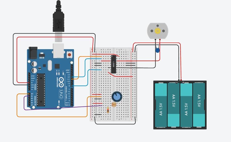
In order to implement the idea of opening and unfolding the I-mesh when light hits the module, an Arduino UNO board was used, which allows you to do without soldering in creating a prototype. The logical idea of the installation is that the light entering the photoresistor should be measured on a scale from 0 to 10, within which for each step the motor rotation time clockwise and counterclockwise will be allocated to open and close the module. This process was achieved using the setup provided below.
At the design and programming stage, it was decided to use the Autodesk TinkerCad online platform to create a virtual model in which you can use all those missing parts, access to which will appear later. To power such elements as the h-bridge L293D, potentiometer and photoresistor, a 5V output was used, which is sufficient for these purposes, and it comes from the Arduino Uno. To power the external motor, which consumes 12V and 3A current, a network adapter was used, which supplied the required voltage. These two power supplies were connected to center lines and used different ground lines.
To use the motor in the widest range and use various adjustments, a potentiometer was used, which allows you to adjust the speed of rotation of the motor by increasing or decreasing the potential falling on its power supply. The photoresistor itself does not have the ability to produce values that could initially be read by the Arduino UNO, since the installation cannot measure resistance. However, you can create a voltage divider using a resistor connected to a photoresistor.
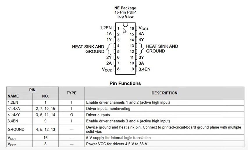
The operation diagram of the H-bridge L293D, which allows the use of the motor in two directions of torsion, is provided below.
Figure 24: Arduino UNO Virtual Installation Using TinkerCAD.
Figure 25: Connection rules and operating principles of H-bridge L293D.
Based on this diagram, the Arduino UNO pins were connected to the driver channels responsible for the perception of this chip in the code, 4 ground connections were made, two power supplies were connected, and the motor itself was connected, which has a choice of 2 variations of counterclockwise and clockwise torsion. If there are problems with orientation on the module, the wires coming from the motor must change their position on the breadboard, for a diametrically opposite movement.
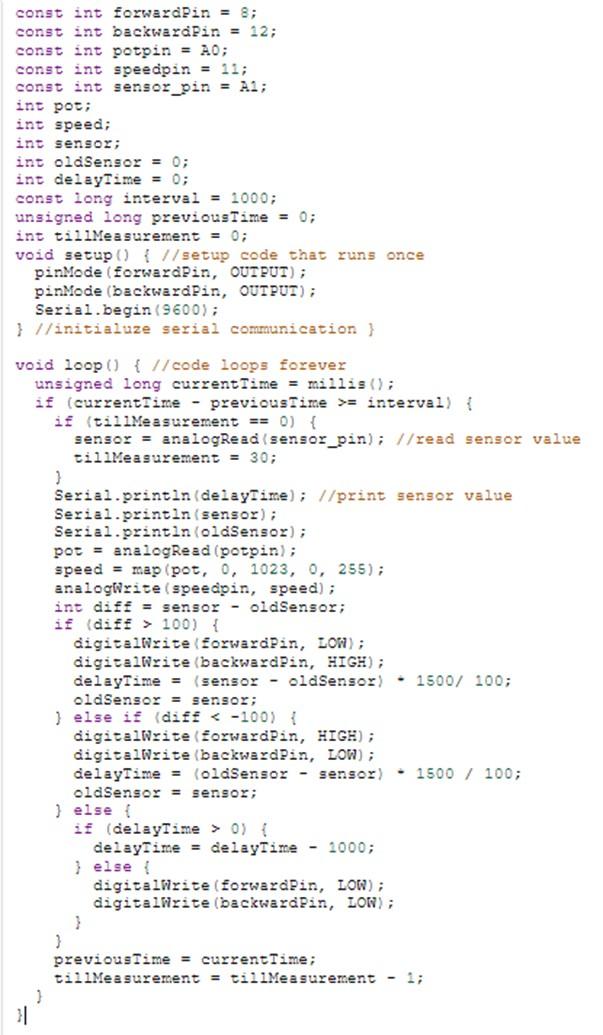
For this installation to work, a code is required that is responsible for the logic of what is happening, and it is presented below
Figure 26: Code for executing module tasks loaded into Arduino UNO.
At the beginning, variables must be set and pin numbers for the necessary elements and correct operation must be indicated. The code uses a time measurement system in milliseconds and therefore the initial time step of 1 second will be displayed as delay = 1000. The code works in such a way that there is a reading value for the old and new sensor, between which you can set the exact amount of time in the measurement interval. For example, the variable tillMeasurement = 30 means that a new measurement will occur every 30 seconds. Next comes the standard setting of the potentiometer, which changes the speed at which the motor rotates.
To determine the step within which the 10-step potentiometer gradation will consist, measurements were taken on a real prototype and the displayed values of sensor and oldsensor were from 0 in complete darkness to 1000 in the brightest light that available means could produce. Thus, the step was taken equal to 100 units of measurement of the photoresistor and when calculating the rotation of the shaft with its diameter and the length I-mesh, by dividing the circumference of the shaft delay by the unit of time with which one gradation of light will be used is equal to 1.5 seconds or 1500 milliseconds. Thus, the difference between the sensor indicators in a 30-second period must be greater than 100 in absolute value so that the motor is set in motion when the light level changes and does not disturb the users of the building. Next, this difference was divided by 100 without a remainder and multiplied by 1.5 seconds to calculate in which direction the motor should turn, then those pins were activated. This happens until the sensor values go into minus; to suspend its operation, a value is constantly subtracted from the value of the Sensor photoresistor. When the 0 mark is passed, the cycle ends, and a new measurement occurs after 30 seconds. Thus, the speed of rotation of the motor, the sensitivity of the
photoresistor, the measurement frequency of the sensor, and the scrolling time per degree of light are flexible parameters that can be changed to suit the needs of the client and his preferences, and the climate of the building being served (Source codes are available in the “Codes” file).
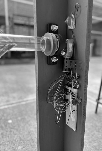
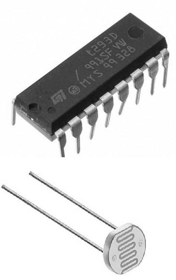
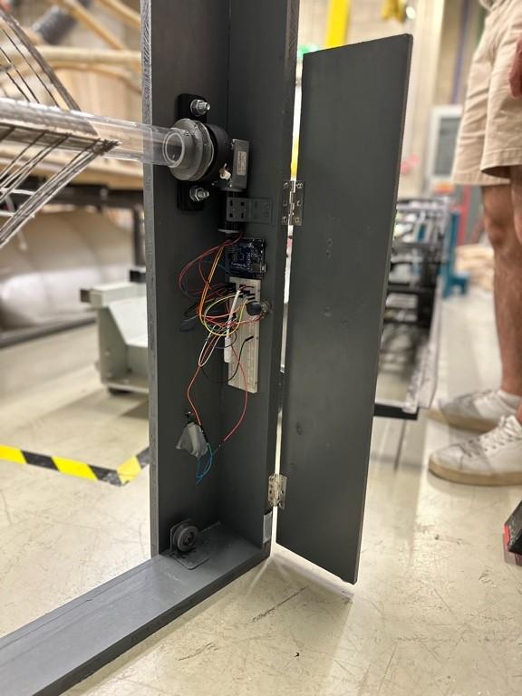
Figure 27: Final installation and elements of h-bridge L293D and photoresistor.
Figure 28: Digital Prototype - Magnification Detail.
5 Discussion
The F.I.D.I.T.I. façade system's results demonstrate a promising potential for enhancing energy efficiency and indoor environmental quality (IEQ) in buildings. The system's ability to autonomously adapt to changing sunlight levels by opening and closing panels optimizes natural light intake, leading to improved thermal comfort and reduced energy consumption for artificial lighting and cooling. This real-time adaptability aligns with the increasing demand for sustainable building designs that prioritize both energy performance and occupant well-being.
The implications of these findings are multifaceted. Practically, the implementation of such dynamic façade systems in office buildings, especially in regions with extreme climates like Kish, Hormozgan, could lead to substantial energy savings and enhanced occupant comfort. The F.I.D.I.T.I. system's modular design and lightweight materials further enhance its practicality and ease of installation, making it a viable solution for both new constructions and retrofits of existing buildings. The reduction in energy use not only lowers operational costs but also contributes to sustainability goals by reducing the building's carbon footprint. Theoretically, these results support the concept that real-time adaptability in building designs can improve both energy performance and occupant satisfaction.
5.1 Frame
The facade of the structure incorporates a sophisticated modular system centered around a main steel frame, ensuring both structural integrity and design flexibility. This steel frame serves as the primary support structure, providing a robust and durable foundation for the entire facade. The modular system is meticulously designed to allow for the easy installation and replacement of individual panels, enhancing the adaptability and maintenance of the building's exterior.
The use of a steel frame offers several advantages, including high strength-to-weight ratio, resistance to environmental factors, and long-term durability. Panels can be prefabricated off-site and then quickly installed on-site, reducing construction time and labor costs. This approach not only improves the overall efficiency of the building process but also minimizes disruptions and waste.
Figure 29: Digital Prototype - Magnification Detail.
6 Limitations
Despite the promising results, certain limitations should be acknowledged. The study period was limited and may not fully encompass the range of seasonal variations and extreme weather events that the system might encounter in real-world applications. Although sophisticated, the computational models used may not perfectly capture all real-world factors, such as the long-term impact of dust, pollution, and wear on the façade's
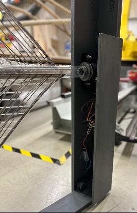
Figure 31: Placement of the motor in the frame of prototype.
performance. Additionally, the study's focus on a specific geographic location (Kish, Hormozgan) suggests that further research is needed to assess the system's adaptability and effectiveness in other climatic regions.
The use of PMMA material for the shafts, while offering advantages in transparency and aesthetics, presents a challenge in attaching the I-mesh fabric. Due to the material's properties, conventional methods like screwing or punching are not feasible. Instead, an automated machine with heating is required for secure attachment, potentially increasing production complexity and cost. This limitation could be addressed in future iterations of the design by exploring alternative materials or attachment mechanisms that are more easily adaptable to standard manufacturing processes. Additionally, the reliance on a single motor for each panel could be a point of failure, and future designs might consider redundant systems for increased reliability.
7 Conclusion
This research demonstrates that the F.I.D.I.T.I. façade system not only enhances energy efficiency and sustainability but also contributes to the aesthetic and functional value of modern architecture. By incorporating advanced sensors and actuators, the façade can dynamically respond to solar radiation. makes it a practical and effective solution for improving energy efficiency and indoor environmental quality. The system's potential for widespread application in both new and existing buildings underscores its importance in the broader context of sustainable architecture. The quantitative results from the radiation analysis, demonstrating a 47.6% reduction in solar heat gain, highlight the system's tangible benefits in mitigating the challenges of hot climates.
Further research and development are needed to address the limitations identified in this study. Long-term performance assessments under diverse weather conditions and in different climatic regions would provide a more comprehensive understanding of the system's capabilities and limitations. The exploration of alternative materials for the shafts and the incorporation of redundant systems could enhance the system's robustness and manufacturability. Additionally, refining the control system and integrating user feedback could further optimize occupant comfort and satisfaction.
In conclusion, the F.I.D.I.T.I. façade system exemplifies the future of adaptive and responsive architecture. Its innovative design and integration of advanced technologies offer a pathway towards more sustainable, energy-efficient, and comfortable buildings. Continued research and refinement of such systems are crucial for meeting the evolving demands of modern urban environments.
8 References
[1] Evaluating the Daylighting Performance of Dynamic Façades by Using New Annual Climate-Based Metrics
[2] A clever combination of sun shading, and façade creates visual harmony - a story by SCHÜCO International KG Published on 07/13/2022 https://www.windoorexpert.eu/news/news,33720,w,a-clever-combination-of-sun-shading-and-fa %C3%A7ade-creates-visual-harmony.html
[3] Simulated historical climate & weather data for Kish Island - Meteoblue https://www.meteoblue.com/en/weather/historyclimate/climatemodelled/kish-island_iran_126913
[4] FABRIC FOR FAÇADE: https://www.i-mesh.eu/ and https://www.i-mesh.eu/technical
[5] MOTOR: LINK
[6] SHAFT: LINK
[7] PULLEYS: LINK
[8] BEARING: LINK
A project by student(s)
Apurva Rairikar Pradeep
Assanali Kaidarov
Farnoosh Rostami
Flora Azarpeivand
Helia Jalali
Mohammad Nikfarjam
Supervised by INDEXLAB
Pierpaolo Ruttico, Carlo Beltracchi, Imane El Bakkali, Zhu Qiulin, Ahmed Elmaraghy, Federico Bordoni, Gabriele Viscardi.