EN-FR
2026
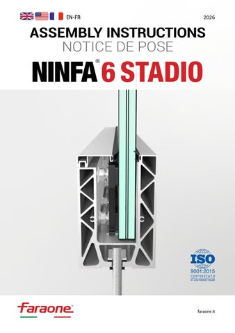
ASSEMBLY INSTRUCTIONS NOTICE DE POSE
faraone.it
NINFA 6 STADIO ASSEMBLY INSTRUCTIONS Stages of preparation for fixing
01. POSITIONING THE BAR - Place the bar - Make the first and last hole - Insert two bolts (threaded rods supplied) to keep the profile in position IMPORTANT: Make sure that the fixing is done on solid masonry
LATO ESTERNO EXTERNAL SIDE
02. DRILLING THE FLOOR Using the pre-drilled profile as a template, mark the position of the holes on the floor with the drill. Then move the profile and drill the floor according to the marks previously made. (Use a 14 mm / 0.55” bit) LATO ESTERNO EXTERNAL SIDE
Note. The profiles are drilled within a 200 mm (7.87”) hole-to-hole distance
03. CLEANING Clean carefully the holes using a special blower, or with compressed air, before applying the chemical resin.
ENGLISH
Note: Follow the manufacturer’s instructions regarding the chemical anchor
FORI Ø14 HOLES Ø14mm mm (0.55”)
04. APPLICATION OF RESIN
RESINA CHEMICAL CHIMICA RESIN
Apply the certified chemical resin. such as RE500V4 (outdoor use) or HY170 (indoor use). Fill the hole about half of its depth. It is recommended to use the dispenser gun
Faraone.it
2
6 STADIO 05. INSERTION OF THE RODS Insert the M12x140/5.51” threaded rods into the holes leaving the required 30 mm (1.18”) protrusion for the profile thickness and the M12 nuts. Then remove any excess resin. 30 mm
30 mm
06. ADHESIVE GASKET Apply the adhesive gasket to the underside of the profile (the side that will be in contact with the floor). It is recommended to apply a sufficient amount of SIKAFLEX (INDEX) or similar sealant to the underside of the profile to protect the threaded rod.
Corner coupling: solutions on pp.14-15
07. PROFILE FIXING Insert as follows: 1. Adhesive gasket 2. Ninfa 6 Stadio profile 3. Fixing bush 4. Flat washer 5. M12 nut
4 2
Note: Ensure that the Ninfa profile adheres to the floor or the load-bearing structure (concrete, steel, etc.). To meet the tightening torque, follow the manufacturer’s instructions for the chemical anchor.
5 3 1
VISTA PROFILO SEZIONATA SECTIONAL PROFILE VIEW 3
Ninfa 6 Stadio Assembly instructions
ENGLISH
When the resin has dried, proceed with the installation.
NINFA 6 STADIO ASSEMBLY INSTRUCTIONS Assembly and installation of the adjusters and glassholding plastic 08. ASSEMBLY OF THE RS SYSTEM
FOR 10+10 (3/8”+ 3/8”) GLASS
10+10
3/8”+ 3/8”
1
2
SPESSORI DA 4(0.15”) mm SHIMS 4 mm
FOR 12+12 (1/2”+ 1/2”) GLASS
12+12 1/2”+1/2”
ENGLISH
1
SENZA SPESSORI WITHOUT SHIMS
Faraone.it
4
6 STADIO 09. INSERTING THE GLASS-HOLDING PLASTIC Tighten carefully the nuts and insert the glass-holding plastic into the profile (4 pieces/meter) (4 pieces/3.28ft).
10. POSITIONING THE GLASS-HOLDING PLASTIC Space the glass-holding plastic as shown in the attached diagram. The example is on a 1 meter (3.28ft) long balustrade.
250
250
250
125
(9.84”)
(9.84”)
(9.84”)
(4.92”)
ENGLISH
125 (4.92”)
Glass-holding Plastica plastic poggia-vetro 5
Ninfa 6 Stadio Assembly instructions
NINFA 6 STADIO ASSEMBLY INSTRUCTIONS Glass positioning and adjusting step 11. GLASS POSITIONING
Guarnizione Gasket già montate already fitted
Incline Inclinare il the glass vetro
Insert the glass in an inwards inclined position, taking care not to touch (twist) the external gasket. IMPORTANT: Place the glass slowly into the profile (a sudden drop of the glass would risk breaking the polycarbonate spacers) The tempered-hardened glass must be positioned with the hardened sheet facing the external side.
1000
(39.37”)
Glass Vetro
Profile Profilo
12. INSERTING THE “RS” SYSTEM Insert the adjusters (“RS” system) for adjusting the vertical plumb of the glass in correspondence with the glass-holding plastic.
ENGLISH
First insert one of the two central adjusters, proceed with the vertical plumb of the glass and then insert the remaining adjusters to complete the adjustment. (4 for each meter/3.28ft)
ATTENTION: Make sure that the flanged nuts are in contact with the head of the M10 screw and are facing the profile Faraone.it
6
6 STADIO 13. VERTICAL PLUMB By orienting the glass plate manually, reach the vertical plumb and consequently tighten the two lower screws and the upper one of the central adjuster, constantly checking the bubble level. Note: an excessive tightening of the adjusters can lead to the opening of the profile and, consequently, to the malfunction of the adjusters.
Vite superiore Upper screw
ENGLISH
ATTENTION: To tighten the adjusters, it is recommended to use a torque wrench with a tightening torque set from 5 Nm. ART. FARAONE KIT-CD
Lower screw Vite inferiore
7
Ninfa 6 Stadio Assembly instructions
NINFA 6 STADIO ASSEMBLY INSTRUCTIONS Glass adjustment and glass gasket installation diagram
14. GLASS INCLINATION ADJUSTER (easy millimetric glass alignment) Check the vertical plumb of the glass with the bubble level. If it is not level, proceed as follows:
2°
Outwards Verso l'esterno
Adjust the inclination of the lass by using the upper and lower screws of the adjusters. To move the glass plate outwards, rotate the lower nuts clockwise; conversely, rotate the upper nuts counterclockwise until the glass is plumb.
Chiave inglesewrench da 15 15 mm (0.51”) mm registro for per the iladjusting
To move the glass plate inwards, rotate the upper nuts clockwise; conversely, rotate the lower nuts counterclockwise. At this point, having found the required inclination, tighten both rows of adjusters.
2°
Inwards Verso l'interno
ENGLISH
15 mm inglese (0.51”) wrench Chiave da 15 for per the iladjusting mm registro
Tutti i registri inserted inseriti All adjusters Faraone.it
8
6 STADIO
Seal at beginning and end
15. HOW TO INSTALL THE GASKET BETWEEN THE GLASS PANELS The adhesive gasket (1) provided in the package is suitable for the height of the Ninfa profile and the thickness of the glass
96
(1)
25
ENGLISH
20
9
Ninfa 6 Stadio Assembly instructions
NINFA 6 STADIO ASSEMBLY INSTRUCTIONS Glass installation and sealing
16. PAIRING PROFILES AND GLASS After positioning the first glass panel, repeat the same installation steps with the next glass panel, making sure to push the second glass panel against the gasket until it is compressed by approximately 1mm (0.03”).
2nd GLASS 2° VETRO
ENGLISH
1st GLASS 1° VETRO
Faraone.it
10
3rd GLASS 3° VETRO
6 STADIO 17. INSERT THE CLADDING When the glass plates are vertically plumb and the adjusters have been properly tightened, insert the snap-fit upper cladding.
Carter da Cladding a to be inserire inserted scatto by snap shut
18. SEALING
ENGLISH
Apply a quantity of adhesive over the adhesive gasket.
11
Ninfa 6 Stadio Assembly instructions
NINFA 6 STADIO ASSEMBLY INSTRUCTIONS Joint cover
19. INSERTING THE JOINT-COVER ACCESSORY After sealing, while the adhesive has not yet hardened, insert the joint-cover accessory (2) and push it down
ENGLISH
(2)
Faraone.it
12
6 STADIO
Final stages of Installation
20. INSERT THE CAPS Screw the side-covering caps with the supplied screws to complete the job. Finished. Make sure you have properly followed all the steps.
ENGLISH
“Good job!”
Side cap
Tappo laterale
13
Ninfa 6 Stadio Assembly instructions
NINFA 6 STADIO ASSEMBLY INSTRUCTIONS Installation Diagram for Linear and Corner Joints
21. ASSEMBLY DIAGRAM OF THE LINEAR PROFILE JUNCTION Proceed as follows: 1. Approach the profiles 2. Position the joint strip from above 3. Screw the joint strip with the self-drilling screws that are in the KIT 4. Insert the snap-fit cladding from above
It is valid for all Ninfa models.
2
1
ENGLISH
4
Faraone.it
14
3
6 STADIO 22. ASSEMBLY DIAGRAM OF THE CORNER PROFILE JUNCTION Proceed as follows: 1. Approach the profiles 2. Position the joint bracket from above 3. Screw the joint bracket with the self-drilling screws that are in the KIT 4. Insert the snap-fit cladding from above
It is valid for all Ninfa models.
1
2
3
ENGLISH
4
15
Ninfa 6 Stadio Assembly instructions
NINFA 6 STADIO ASSEMBLY INSTRUCTIONS Optional: N6-P1 and N6-P2 handrail
23. GLASS PREPARATION Apply a layer of adhesive to the upper edge of the glass. The type of adhesive to use may be defined together with the adhesive supplier.
N6-P1 10+10 12+12 VETRO 12+12 (1/2”+1/2”) GLASS 10+10VETRO (3/8”+3/8”)GLASS
24. HANDRAIL INSTALLATION Select the handrail model according to the glass thickness (10+10/12+12) (3/8”+3/8” / 1/2”+1/2”)and insert the profile from above, applying pressure.
ENGLISH
N6-P2 VETRO 10+10 10+10 (3/8”+3/8”)GLASS
Faraone.it
16
6 STADIO 25. HANDRAIL JOINTS
GIUNZIONE LINEARE LINEAR JOINT
GIUNZIONE CORNERANGOLARE JOINT
Linear joint: apply adhesive to the inner part of the joint and insert it from above. Corner joint: insert the corner joint inside the handrail and screw it from below.
26. INSERTING THE END CAPS
ENGLISH
Screw the side cover caps using the supplied screws to complete the job.
17
Ninfa 6 Stadio Assembly instructions
NINFA 6 STADIO ASSEMBLY INSTRUCTIONS Optional: N6-P3 handrail
27. GLASS PREPARATION Apply a layer of adhesive to the upper edge of the glass. The type of adhesive to use may be defined together with the adhesive supplier.
N6-P3 10+10 10+10 VETRO (3/8”+3/8”) GLASS
28. HANDRAIL INSTALLATION
ENGLISH
Select the handrail model according to the glass thickness (10+10) (3/8”+3/8”) and insert the profile from above, applying pressure.
Faraone.it
18
6 STADIO GIUNZIONE LINEARE LINEAR JOINT
29. HANDRAIL JOINTS Linear joint: apply adhesive to the inner part of the joint and insert it from above.
30. INSERTING THE END CAPS
ENGLISH
Screw the side cover caps using the supplied screws to complete the job.
19
Ninfa 6 Stadio Assembly instructions
NINFA 6 STADIO ASSEMBLY INSTRUCTIONS Optional: LED Pack
31. WIRING Arrange the power cables inside the dedicated housing and secure them with the snap-fit clips.
32. DRILLING THE CLADDING
ENGLISH
Prepare a hole inside the cladding for cable routing.
Faraone.it
20
6 STADIO 33. FIXING THE CLADDING Fix the cladding profile to the Ninfa profile using two screws. NB: Do not drill near the reinforcing ribs.
34. POWER CABLE CONNECTION
ENGLISH
Connect the power cables to the LED strip cables. Then glue the LED strip and finally close the snap-fit plastic cladding.
21
Ninfa 6 Stadio Assembly instructions
NINFA 6 STADIO ASSEMBLY INSTRUCTIONS Optional: LED Pack
35. LED PACK
ENGLISH
Finished. Make sure you have followed all the steps.
Faraone.it
22
6 STADIO LED POSITIONING OPTIONS NB: Do not drill near the stiffening ribs
EXTERNAL
INTERNAL/EXTERNAL
VARIABLE VERTICAL POSITIONING
ENGLISH
INTERNAL STEP LIGHT
23
Ninfa 6 Stadio Assembly instructions
NINFA 6 STADIO ASSEMBLY INSTRUCTIONS Optional: LED lights in the cladding
36. INSTALLATION OF THE LED STRIP IN THE CLADDING The LED strip must be equipped with an adhe-sive backing on the rear to allow perfect anchoring and alignment within the de-dicated channel inside the aluminium cladding.
ATTENTION: It is recommended to use LED strips with a protection rating of at least IP65/68 and with heat resistance ratings certified according to the MS CG-12 and GM6073 tests.
7
Adhesive backing Banda adesiva
10
ENGLISH
3 2
1 1. Position the LED strip and the cladding 2. Glue the LED strip to the inner side of the cladding 3. Insert the assembled unit onto the Ninfa profile
Faraone.it
24
6 STADIO LED POSITIONING OPTIONS
external
ENGLISH
internal
25
Ninfa 6 Stadio Assembly instructions
EXPOSED CUT-EDGE SURFACE PROTECTION “Bonderite” treatment or similar HOW TO PROTECT THE CUT PROFILE Treat the cut faces with a protective product (such as Bonderite).
Exposed 90° Taglio vivo a cut 90°
Bonderite or similar o similare
ENGLISH
Taglio vivo a cut 45° Exposed 90°
Bonderite or similar o similare
Faraone.it
26
WE TAKE CARE OF YOUR PROJECTS Our experience at your service. We guide you in choosing the best solution for your needs.
EXPERT GUIDE Managing a project through all its phases can be challenging. That is why we provide comprehensive support, from technical consultation through to after-sales service.
INSTALLATION We carefully select the experts who carry out the installation of our products to ensure our quality standards. During this phase, tests are carried out on site to ensure that the installation has been performed in a competent manner and that everything is safe.
Memberships: ENGLISH
How to contact us: email: faraone@faraone.it Tel: +39 0861 784200 web: faraone.it | faraone-parapetti.it
Request information on our website
27
Ninfa 6 Stadio Assembly instructions
ENGLISH Faraone.it
28
FRANÇAIS NOTICE DE POSE Modèle Ninfa 6 Stadio
6 STADIO
29
NOTICE DE POSE NINFA 6 STADIO Étapes de préparation à la fixation
01. POSITIONNEMENT DE LA BARRE - Placez la barre - Faites le premier et le dernier trou - Insérez deux tiges filetées (fournies) pour maintenir le profilé en position IMPORTANT : Assurez-vous que la fixation est faite sur de la maçonnerie solide
LATOEXTÉRIEUR ESTERNO CÔTÉ
02. PERCEMENT DE LA DALLE En utilisant le profilé déjà percé comme gabarit, marquez la position des trous sur la dalle avec la perceuse. Déplacez ensuite le profilé et percez la dalle à l’endroit des repères précédemment réalisés.(Utilisez une mèche diamètre 14 mm) LATOEXTÉRIEUR ESTERNO CÔTÉ
Note : Les profils sont percés tous les 200 mm
03. NETTOYAGE Nettoyer soigneusement les trous à l’aide d’une soufflette spéciale, ou à l’air comprimé, avant d’appliquer la résine chimique. Note : Suivre les instructions du fabricant de l’ancrage chimique
FORI Ø14 TROUS Ø14mm mm
RESINA RÉSINE CHIMICA CHIMIQUE
FRANÇAIS
04. APPLICATION DE LA RÉSINE Appliquez la résine chimique certifiée, type RE500V4 (usage extérieur) ou HY170 (usage intérieur). Remplissez le trou à environ la moitié de sa profondeur. Il est recommandé d’utiliser le pistolet avec doseur Faraone.it
30
6 STADIO 05. INSERTION DES TIGES Insérez les tiges filetées M12x140 dans les trous en laissant le dépassement de 30 mm requis pour l’épaisseur du profilé et les écrous M12 et nettoyez l’excès de résine. 30 mm
S’il y a une cale pour l’évacuation des eaux, augmentez le dépassement de la tige M12x140 de 8 mm, soit 38 mm au total. 30 mm
06. JOINT ADHÉSIF Coller le joint adhésif sur la face inférieure du profilé (celle qui sera en contact avec le sol). Appliquer une quantité suffisante de SIKAFLEX (INDEX) ou similaire sur la partie inférieure du profilé afin de protéger la tige filetée.
Couplage d’angle : solutions aux p.40-41
07. FIXATION DU PROFILÉ Lorsque la résine a séché, procédez à l’installation. Suivez l’ordre qui suit :
4 2
Note : Assurez-vous que le profilé Ninfa soit bien fixé au sol ou à la structure porteuse (béton, acier, etc.)
VISTA DU PROFILO COUPE PROFILSEZIONATA
Pour respecter le couple de serrage, suivez les instructions du fabricant de l’ancrage chimique.
31
5 3 1
Notice de pose Ninfa 6 Stadio
FRANÇAIS
1. Joint adhésif 2. Profilé Ninfa 6 Stadio 3. Bague de fixation 4. Rondelle plate 5. Écrou M12
NOTICE DE POSE NINFA 6 STADIO
Préparation et installation du systèmes de réglage et les systèmes d’appui et calage extérieur 08. PRÉPARATION DU SYSTÈME « RS »
VERRE ép 10+10
10+10
1
2
SPESSORI 4 mm CALES DE DA 4 mm
VERRE ép 12+12
12+12
1
FRANÇAIS
SANS SENZACALES SPESSORI
Faraone.it
32
6 STADIO 09. PLACEZ LES SYSTÈMES D’APPUI ET CALAGE EXTÉRIEUR Serrez soigneusement les écrous et insérez dans le profilé les systèmes d’appui et calage extérieur (4 pièces/ mètre)
10. POSITIONNEMENT DES SYSTÈMES D’APPUI ET CALAGE EXTÉRIEUR Calez les systèmes d’appui et calage extérieur comme indiqué dans le schéma joint. L’exemple concerne une balustrade d’1 mètre de longueur.
250
250
250
125
33
Notice de pose Ninfa 6 Stadio
FRANÇAIS
125
Plastica Système poggia-vetro de réglage
NOTICE DE POSE NINFA 6 STADIO Phase de positionnement et réglage du verre
11. POSITIONNEMENT DU VERRE
Les joints sont Guarnizione déjà en place già montate
Inclinez Inclinare il le verre vetro
Insérez le verre dans une position inclinée vers l’intérieur, en prenant soin de ne pas frotter le joint extérieur. IMPORTANT : Placez délicatement le verre dans le profilé (une chute du verre risquerait de casser les cales en polycarbonate). Le verre trempé doit être positionné avec la plaque trempée vers l’extérieur.
1000
Verre Vetro
Profilo Profilé
12. INSÉRER LE SYSTÈME « RS » Insérez les régleurs (système RS) pour ajuster la mise à plomb verticale du verre au niveau des plastiques porte-verre.
FRANÇAIS
Insérez d’abord l’un des deux régleurs centraux, procédez à la mise à plomb du verre, puis insérez les régleurs restants pour terminer le réglage. (4 par mètre)
ATTENTION : Assurez-vous que les écrous à bride sont en contact avec la tête de la vis M10 et face au profil Faraone.it
34
6 STADIO 13. MISE À PLOMB En orientant manuellement le panneau de verre, atteindre le niveau de mise à plomb et par conséquent serrez les vis inférieures et supérieures du système de réglage au centre du panneau de verre, en vérifiant constamment le niveau de la bulle. Note : Un serrage excessif des écrous peut entraîner l’ouverture du profilé et, par conséquent, le dysfonctionnement du système.
Vis supérieure Vite superiore
Vis inférieure Vite inferiore
35
FRANÇAIS
ATTENTION : Pour le serrage des réglages, il est recommandé d’utiliser une clé dynamométrique réglée sur un couple de serrage de 5 Nm. ART. FARAONE KIT-CD
Notice de pose Ninfa 6 Stadio
NOTICE DE POSE NINFA 6 STADIO Réglage du verre et schéma de montage du joint entre les vitres
14. RÉGLAGE DE L’INCLINAISON DU VERRE (ALIGNEMENT MILLIMÉTRIQUE) Vérifiez la mise à plomb du verre avec le niveau, puis réglez l’inclinaison du verre en utilisant les vis des réglages inférieures et supérieures.
2°
Vers Versol’extérieur l'esterno
Pour pousser le panneau vers l’extérieur, desserrez les vis inférieures et serrez les vis supérieures, jusqu’à ce que le verre soit à plomb. Chiave Clé inglese damm 15 de 13 mmpour per le il registro réglage
À l’envers, pour pousser le verre vers l’intérieur, desserrez les vis supérieures et serrez les vis inférieures. Quand vous avez trouvé l’inclinaison souhaitée, serrez les deux rangées de réglages.
2°
Vers Versol’intérieur l'interno
FRANÇAIS
Clé de 13 Chiave inglese da mm 15 réglage mmpour per le il registro
Tutti iles registri inseriti Tous régleurs sont insérés Faraone.it
36
6 STADIO
Scellez au debut et a la fin
15. COMMENT POSER LE JOINT ENTRE LES PANNEAUX DE VERRE Le joint adhésif (1) fourni dans l’emballage est adapté à la hauteur du profilé Ninfa et à l’épaisseur du verre.
96
(1)
25
FRANÇAIS
20
37
Notice de pose Ninfa 6 Stadio
NOTICE DE POSE NINFA 6 STADIO Pose des verres et scellement
16. ASSEMBLER LES PROFILÉS ET LE VERRE Après avoir disposé le premier panneau de verre, répétez la même séquence de montage avec le suivant en prenant soin de pousser le deuxième panneau de verre contre le joint adhésif jusqu’à ce qu’il soit pressé d’environ 1 mm.
FRANÇAIS
1° VETRO 1er VERRE
2° VETRO 2e VERRE
Bouchon profilé Ninfa Sceller le début et la fin après avoir mis le bouchon Faraone.it
38
3° VETRO 3e VERRE
6 STADIO 17. INSTALLER LA PARCLOSE À CLIPSER Lorsque les panneaux de verre sont à plomb et que les régleurs sont correctement serrés, insérez la parclose supérieure à clipser.
Carter à da Parclose inserire a clipser scatto
18. SCELLER
FRANÇAIS
Appliquer une quantité de colle sur le joint adhésif.
39
Notice de pose Ninfa 6 Stadio
NOTICE DE POSE NINFA 6 STADIO Accessoire pour cache-joint
19. INSÉRER L’ACCESSOIRE CACHE-JOINT Après le scellement, lorsque la colle n’est pas encore durcie, insérer l’accessoire cache-joint (2) en poussant vers le bas.
FRANÇAIS
(2)
Faraone.it
40
6 STADIO
Dernières étapes de montage 20. INSÉRER LES EMBOUTS Vissez les embouts latéraux avec les vis fournies pour terminer la pose. Fini. Vérifiez si vous avez suivi les instructions correctement. « Bon travail ! »
Embout latéral
FRANÇAIS
Tappo laterale
41
Notice de pose Ninfa 6 Stadio
NOTICE DE POSE NINFA 6 STADIO
Schéma de montage des connecteurs droits et d’angle
21. CONNECTEURS LINÉAIRES DES PROFILÉS Procédez dans l’ordre suivant : 1. Approchez les profils 2. Positionnez le connecteur par le haut 3. Vissez le connecteur avec les vis auto-perceuses 4. Installez le carter à clipser à pression
Adapté pour tous les modèles Ninfa
1
2
FRANÇAIS
4
Faraone.it
42
3
6 STADIO 22. CONNECTEURS D’ANGLE DES PROFILÉS Procédez dans l’ordre suivant : 1. Approchez les profils 2. Positionnez le connecteur par le haut 3. Vissez le connecteur avec les vis auto-perceuses 4. Installez le carter à clipser
Adapté pour tous les modèles Ninfa
1
2
3
FRANÇAIS
4
43
Notice de pose Ninfa 6 Stadio
NOTICE DE POSE NINFA 6 STADIO En option : main courante N6-P1 et N6-P2
23. PRÉPARATION DU VERRE Appliquer une couche de colle sur le bord supérieur du verre. Le type de colle à utiliser peut être défini avec le fournisseur de colle.
N6-P1 VETRO 10+10 VETRO VERRE VERRE 12+12 12+12
24. POSE DE LA MAIN COURANTE Sélectionner le modèle de main courante selon l’épaisseur du verre (10+10/12+12) et insérer le profilé par le haut en exerçant une pression.
FRANÇAIS
N6-P2 VETRO 10+10 VERRE
Faraone.it
44
6 STADIO 25. CONNECTEURS POUR MAIN COURANTE
GIUNZIONE LINÉAIRE LINEARE CONNECTEUR
GIUNZIONE ANGOLARE CONNECTEUR D’ANGLE
Connecteur linéaire : appliquer l’adhésif à l’intérieur du joint et l’insérer par le haut. Connecteur d’angle : insérer la jonction d’angle à l’intérieur de la main courante et la visser par le dessous.
26. INSÉRER LES EMBOUTS DE FERMETURE
FRANÇAIS
Visser les embouts latéraux de finition avec les vis fournies pour terminer la pose.
45
Notice de pose Ninfa 6 Stadio
NOTICE DE POSE NINFA 6 STADIO En option : main courante N6-P3
27. PRÉPARATION DU VERRE Appliquer une couche de colle sur le bord supérieur du verre. Le type de colle à utiliser peut être défini avec le fournisseur de colle.
N6-P3 VETRO VERRE 10+10
28. POSE DE LA MAIN COURANTE
FRANÇAIS
Sélectionner le modèle de main courante selon l’épaisseur du verre (10+10) et insérer le profilé par le haut en exerçant une pression.
Faraone.it
46
6 STADIO CONNECTEUR LINÉAIRE GIUNZIONE LINEARE
29. CONNECTEURS POUR MAIN COURANTE Connecteur linéaire : appliquer l’adhésif à l’intérieur du joint et l’insérer par le haut.
30. INSÉRER LES EMBOUTS DE FERMETURE
FRANÇAIS
Visser les embouts latéraux de finition avec les vis fournies pour terminer la pose.
47
Notice de pose Ninfa 6 Stadio
NOTICE DE POSE NINFA 6 STADIO En option : Pack LED
31. CÂBLAGE Prévoir le câblage des câbles d’alimentation dans le logement prévu à cet effet et les bloquer avec les clips à encliqueter.
32. PERCER LE CARTER
FRANÇAIS
Prévoir un trou à l’intérieur du carter pour le passage des câbles.
Faraone.it
48
6 STADIO 33. FIXATION DU CARTER Fixer, au moyen de deux vis, le profilé de carter au profilé Ninfa. ATTENTION : Ne pas percer à proximité des nervures de renfort.
34. RACCORDEMENT DU CÂBLE D’ALIMENTATION
FRANÇAIS
Raccorder les câbles d’alimentation à ceux de la bande LED. Coller ensuite la bande LED puis fermer le carter en plastique à encliqueter.
49
Notice de pose Ninfa 6 Stadio
NOTICE DE POSE NINFA 6 STADIO En option : Pack LED
35. PACK LED
FRANÇAIS
Terminé. S’assurer d’avoir respecté toutes les étapes.
Faraone.it
50
6 STADIO OPTIONS DE POSITIONNEMENT LED
NB : Ne pas percer à proximité des nervures de renfort.
BALISAGE INTÉRIEUR
EXTÉRIEUR
INTERNE / EXTERNE
FRANÇAIS
POSITIONNEMENT VERTICAL VARIABLE
51
Notice de pose Ninfa 6 Stadio
NOTICE DE POSE NINFA 6 STADIO En option : LED dans la parclose
36. INSTALLATION DE LA LED DANS LA PARCLOSE Le ruban doit être équipé d’une bande adhésive au dos pour permettre un ancrage parfait et un alignement à l’intérieur du canal dédié dans la parclose en aluminium.
ATTENTION : Il est recommandé d’utiliser des rubans LED disposant d’un indice de protection d’au moins IP65/68 et d’une résistance à la chaleur selon les tests MS CG-12 et GM6073.
7
Bande Bandaadhésive adesiva
10
3 2
FRANÇAIS
1 1. Positionner la bande LED et la parclose 2. Coller la bande LED sur le côté intérieur de la parclose 3. Insérer l’ensemble assemblé sur le profil Ninfa
Faraone.it
52
6 STADIO OPTIONS DE POSITIONNEMENT LED
extérieur
FRANÇAIS
intérieur
53
Notice de pose Ninfa 6 Stadio
PROTECTION DES SURFACES À COUPE VIVE Traitement « bonderite » ou similaire COMMENT PROTÉGER LE PROFILÉ COUPÉ Traiter les faces de coupe avec un produit protecteur (type Bonderite).
Coupe viveaà 90° Taglio vivo
Bonderite ou similaire o similare
Taglio vivo Coupe vive aà 45°
FRANÇAIS
Bonderite ou similaire o similare
Faraone.it
54
NOUS PRENONS EN CHARGE VOS PROJETS Notre expérience à votre service. Nous vous guidons dans le choix de la meilleure solution pour vos besoins.
GUIDE EXPERT Suivre un projet dans toutes ses phases n’est pas toujours simple. C’est pourquoi nous vous fournissons une assistance complète, du conseil technique jusqu’au service aprèsvente.
INSTALLATION Nous sélectionnons les experts qui réalisent l’installation de nos produits pour garantir le standard de qualité. Durant cette phase, des tests sont effectués sur chantier pour nous assurer que la pose a été réalisée dans les règles de l’art et que tout soit sécurisé.
Comment pouvez-vous nous contacter : email : faraone@faraone.it Tel : +39 0861 784200 web : faraone.it | faraone-parapetti.it
Membre de :
FRANÇAIS
Demandez des informations sur notre site
55
Notice de pose Ninfa 6 Stadio
faraone.it CAT-IST-NINFA 6 STADIO-EN-FR
(09/2026 - R00)