9 minute read
Rotoweld


M A G A Z I N E
GMAW Automated pipe spool welding solution: "Rotoweld"
Advertisement
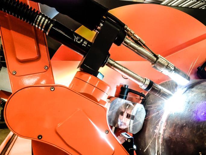
The Rotoweld is a fully automated pipe welding work cell developed specifically for industrial pipe prefabrication, small pressure vessels manufacturing or other similar 1G welding. It integrates machine vision, adaptive control and robotics technology in a complete dedicated solution that is fast and offers full penetration 1G high quality welding. This system is up to 5 times faster than SMAW and uses GMAW for the root, the hot pass and the cap. The work cell will process spools from 4" to 42". The Rotoweld welding torch is standing still and the www.rstafricaguide.com
pipe spool rotates on the idler rollers. It can weld pipe to pipe and pipe to fitting connections and welds carbon steel pipes with standard wall in one dia-inch per minute!! Not only is it fast also it is easy to operate and erases human errors in the welding process by its adaptive control. This results that even not experienced welders can perform quality welds after training by us.
"Welding one dia-inch per minute with the Rotoweld"
The Rotoweld can completely weld for example 12" carbon steel pipe with standard wall in only 12 minutes. The Rotoweld 3.0 welds the root with GMAW and the fill and the cap with GMAW, FCAW or SAW. Optional you can choose to work with a single bay or twin bay, obviously the twin bay system has major advantages and it also is the most sold one. The twin bay is the most efficient and most obvious one to purchase because of the efficient way of work on two bays at the same time and the higher output this leads too.
Adaptive control during welding
The vision based welding technology enables the operator to control the complete process. The system continuously analyses the image of the root weld pool picked up by a video camera incorporated in the welding arm. Unique algorithms use this information to adjust welding parameters such as travel speed, wire feed rate, arc voltage and weaving width, constantly adapting the process to varying conditions such as changes in gap, alignment, root face, or temperature. full-penetration root pass in an open bevel joint represents the epitome of pipe welding skill, and this applies in the fabrication of pipe spools; that is, a subassembly of pipes and fittings welded in pipe shops and then sent into the field. If the welder deposits metal too far above the weld pool, it sinks and cools prematurely, so fusion is incomplete. But if the welder keeps the arc in front of the weld pool, and at just the right height, hot metal flows toward the root and, voila! he gets a fullpenetration root pass that should pass muster. The Rotoweld has the knowledge of highly experienced welder and will therefore for come lack of fusion by it's adaptive control. The operator should only monitor the welding process and might now and then correct the welding process when the system provides a signal. In 2014 the company released the third iteration of the technology, Rotoweld 3.0, which uses a custom robot to perform 1G girth welds. The robot arm performs the root, fill, and cap passes with one welding gun, though the system still can be configured with multiple processes. For instance, a thick walled pipe might call for gas metal arc welding (GMAW) for the root pass and submerged arc welding (SAW) for the fill and cap passes. Visit our dedicated website for this machine on www.pipespoolwelding.com

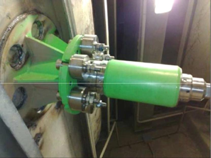
Rotoweld 3.0,( Twin Bay) Automated pipe spool welding machine.

info@hornet.cc
www.hornet.cc

Flow Industries' Silo-Flow system employ a technology using a new, proven concept of cyclical sudden, high-pressure air discharges (up to 3000 PSI or 200 bars) for eliminang blockages and accumulaons in all types of silos, hoppers, bins and bunkers at cement, chemical and steel plants as well as at power staons.
Limitation of existing solutions Existing solutions of bulk material flow are usually air blasters or cannons and Cardox. An air cannon consists of a fast-acting normally-closed valve and a pressure tank. The tank may be of various capacities and is filled with air compressed up to 100 PSI (7 bar). The cannon releases the compressed air from the pressure tank into a storage or process vessel and this discharge is supposed to break down accumulations and blockages. In many cases, the maximum pressure amplitude of 100 psi of traditional air blasters is not sufficient to do the job effectively. To overcome the disadvantage of low power discharges, plants usually install a great number of cannons. Since bulk material has usually cracks and holes, a part of the air released by the cannon immediately escapes over the paths of the least resistance, causing immediate pressure drop and making the process even less efficient. For hard buildups like in hightemperature facilities, air cannons slightly reduce the rate of buildup formation but are very inefficient to clean them or maintain the surface clean. Cardox is a method of converting liquid carbon dioxide into gas inside the tube containing at one end a bursting disc. Gas rapidly expanding in the tube breaks the disc and creates a blast outside the tube. The method is used mostly to clean hard buildups in hightemperature facilities and creates only a single blast per charge. The method is inconvenient and expensive while has a potential to damage the refractory. Silo-Flow™ General. The Silo-Flow™ patented technology has been developed and marketed worldwide by Flow Industries Ltd. Silo-Flow™ devices (SFDs) are pneumatic devices for sudden multipulse release of air compressed at up to 3000 psi (200 bar) into the plant storage or process vessel to meet unique application requirements.
Operation. Silo-Flow™ system consists of SFD, a control panel (CP), one or two standard high-pressure tanks and a dedicated high-pressure compressor (Figure 1). The compressor supplies air to the high-pressure tanks, which are connected to the SFD by a highpressure tubing through a normally closed CP valve, so that in the standby mode the SFD is not under pressure. The SFD is attached to the vessel wall by a mounting socket enabling insertion of the SFD nozzle into the vessel. The system can be activated from the control room by a standalone timer or manually by opening the CP valve and allowing the compressed air from the cylinders to flow freely into the SFD. As soon as compressed air reaches the SFD, it continuously creates powerful air pulses (blasts) with the frequency of one pulse per three or four seconds as long as the air supply is activated. Each such pulse results in a shock wave followed by a high velocity air stream. The shock wave and air stream inside the plant vessel dislodge any blockage or build-ups inside. The SFD is programmed to 'fire' at predetermined intervals, depending on the application. In addition, air pressure is fully controlled from as low as 300 psi (20 bar) to 3000 psi (200 bar).
The SFD working principle is based on a unique innovative concept of continuous firing of blasts triggered by the incoming high-pressure gas. Pressure of the gas flowing into the device governs the firing power. The higher the gas pressure, the stronger the firing pulse. In general, the SFD consists of two chambers separated by a piston. When air is fed into the device, the inlet chamber is filled more quickly and has a higher pressure than the pressurized chamber. This keeps the piston in a closed (charged) position (See Figure 2A). As gas continues to fill the SFD, the pressure in the pressurized chamber increases and becomes close to that of the Inlet chamber. Because of the different piston surfaces exposed to the chambers, the piston is eventually forced towards the inlet chamber and opens the discharge ports releasing the energized compressed air stored in the pressurized chamber (See Figure 2B). This burst of air is directed into the storage or process vessel through release and atmospheric pressure inside, the sudden jump in pressure inside the vessel creates an tunnels alongside the SFD body. When the compressed air reaches the vessel instant shock wave and a strong turbulent air flow throughout the material inside. Silo-Flow replacing natural gypsum with synthetic gypsum The availability and low cost of synthetic gypsum (a by-product of power plant activity) has enabled cement producers to reduce the demand for mined (natural) gypsum. But synthetic gypsum is a cohesive material and has much more problematic properties than natural gypsum, causing severe flow and operational problems industrywide, regardless of the gypsum bin design or cover. These flow problems significantly impact productivity, to the extent that cement manufacturers avoid replacing natural gypsum with synthetic. Like many other cement plants, the Lehigh plant in Alabama tried to replace natural gypsum with synthetic, but experienced severe problems with the flow of synthetic gypsum in its feeder bins although there was no problem with natural gypsum flow. Despite the installed air cannons (several per bin), the gypsum bins would severely clog with the synthetic gypsum, so the plant continued using the more expensive natural material. The plant engineers were frustrated with the continued inability to use to the synthetic gypsum. When they heard that Silo-Flow technology assured continuous and stable material flow, they decided to try it at the plant. The plant had the device fire for 25 seconds (5 'shots') every 20 min at about half its maximum power (1500 psi). After several trials with various mixtures of synthetic and natural gypsum, they moved to 100% synthetic gypsum. The SFD maintained continuous material flow of 100% synthetic gypsum at all times. The plant achieved huge savings with the move to 100% synthetic gypsum and paid back the investment in less than a year.
Silo-Flow eliminates fly ash and coal blockage in power plant hoppers.
Ashkelon power station in Israel, like many other plants, experienced severe flow problems with their fly ash and coal hoppers. These problems affected process efficiency, raised maintenance expenses, and caused costly process interruptions. Air cannons (several per hopper) couldn't solve the problem. The plant searched for an efficient and safe method to prevent such problems, and chose Silo-Flow system. The plant installed one Silo-Flow device per hopper and that was enough to solve completely the plant material flow problems. gypsum and paid back the investment in less than a year.
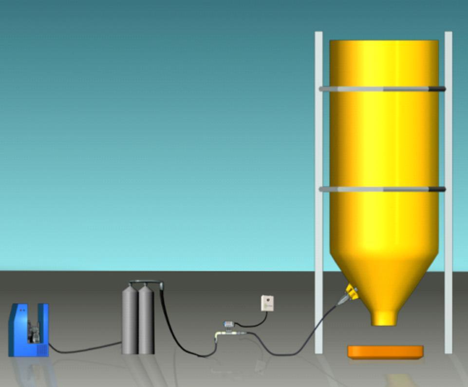
Typical Silo-Flow™ System Configuraon