43 minute read
Case Studies of Asset Management using Markov based model

by Exicon

Musleh Alameri, Wael Emara, National Grid– Saudi Arabia
Abstract This paper analyzes the three-case studies for aging electrical assets which have highly impacted the technical key performance indicators (KPIs) in Jubail city, Saudi Arabia. It has been discussed the optimal way for the operating expenses on that asset and shown how to be reflected in its reliability as a KPIs. The paper applied to 115 kV overhead transmission line and 13.8 kV switchgear on the National Grid SA Company. This research highlighted the benchmarks to expand the asset life cycle with minimization of the expenses or to take a decision to replace it using Markov based model
Advertisement
Index Terms Asset management (AM), Reliability, Key performance indicator (KPI), maintenance, Asset life cycle.
I. INTRODUCTION
Aasset management, extending the asset life cycle, optimizing operation operational expenditure (OPEX) , and improving key performance indicators (KPIs) are substantial topics in the electrical network. The governments and national electricity companies are investing billions of dollars to build reliable electrical grids. These assets have a specified life cycle such as 30,40 or 50 years, then, after that age, the assets must be replaced or bear the consequences of its poor dependabi lity. However, there is a third option to expand the asset life using the asset management (AM) approach. AM is operating the asset on the optimal way to assuring a proper return [1].
The Asset Management (AM) on National Grid SA (NGSA) aimed to find the optimal balance between Risks, Costs, and Performance. The Asset Risk management contains several aspects to evaluate it as the compliance, the safety of assets and human, energy lost reliability, reputation, financial cost, and likelihood.
In this paper, a system consisting of an ageing 115 kV overhead transmission line and 13.8 kV switchgear. It will study the impact of (AM) on their (KPIs) included Energy Not supplied (ENS), the System average interruption duration index (SAIDI), the system average duration frequency index (SAIFI), the momentary average interruption frequency index (MAIFI), and the forced outage frequency index (FOFI). Additionally, the research assesses the (OPEX) and how to be affected by the interpretation indicators and the forced outages cost.
The OPEX on this research be made up of materials, equipment, tools, manpower costs, and the forced outages cost (FOC), the FOC comprise the same factors with opportunity costs from ENS loses which is that supposed money to gain it from the consumer in case no interruption
II. OBJECTIVE
Asset Management (AM) aims to increase asset return while maintaining a certain level of reliability. The AM difficulty and challenges increased with the ageing of equipment. The objectives of the paper are:
• Determine and analyze the OPEX for a specific asset that considering in the paper case studies.
• Define and evaluate the technical KPIs for those assets.
• Investigate the relationship between the expenses and their impact on the KPI.
• Apply Markov based model on the case studies
The Asset Management of ageing equipment provides an optimal way for the expenses and ensures the financial and technical return on the investment is taken.
III. PROBLEM FORMULATION
The purpose of this paper is to achieve the maximum return of operational expenditure. The return knows to be a financial, technical improvement, or minimize the asset risk
A. Main Objective Function:
The main objective function of Asset Management is a combination of three main topics, which are OPEX, KPI, and Asset risk, it can be expressed as:
Were, R Return on the investment.
OPEX Operational expenditure KPIs Key Performance Indicators.
B. Operational Expenditure:
The Operational Expenditure can be formulated in this research paper as :
OPEX = �������� + �������� + ������������ (2)
Were, MB Manpower cost
MT Materials cost
FOC Forced outages cost
C. Forced Outages Cost:
On the other hand, the forced outage costs which mainly on the interpretation time can be devised as:
������������ = Opc + MB + MT (3)
Were,
������������ = ������������ ∗ ������������ ���������������������������� (4) Opc and ENG are Opportunity cost Energy not supplied, respectively.
D. Asset Risk Register:
������������ = ������������������������������������������������ × Probaility (5)
Were,
������������������������������������������������ = ∑5(C 1 + S + ELR + R + FC) (6) ARR Asset Risk Register
C Compliance
S Safety of assets and human
ELR Energy lost reliability
R Reputation
FC Financial costs
E. Reliability Indices:
To study the power quality and reliability of the system we need to calculate different indices [2,3]
������������% = ∑(���������������� ������������(��������) ×���������������� ���������������� ��������������������������������(����)) ×100
�������������������� ������������������������ �������������������������������� (������������) (7)
�������������������� = ∑ �������������������������������� �������� ������������������������������������ ���� ���� ������������������������������������������������ ������������������������ �������������������� �������� �������� �������������������������������� ������������������������ (8)
IV. METHODOLOGY
A. Markov based model:
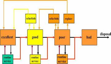
The Markov based model classifies the asset condition into four stages, the time of need for refurbishing/replacement is defined as shown in Fig.1. However, it depends on many criteria to confirm which routing services are, and what is the action needs.
B. Run, Repair, Refurbish , and Replace Decisions:
The Asset Management has the popular strategic which called run, repair, refurbish and replace [6], the question is for the companies how could minimize the repair and refurbish as well as extend the asset life cycle, on the other hand when the organization takes the decision stope the expenses on the asset by taking actions such as replace or disposal the asset. It is difficult to find an answer that can be applied to every company, although, this paper will touch some practices that can be applied to minimize the OPEX and facilitate decision making.
1. Maintenance Strategies:
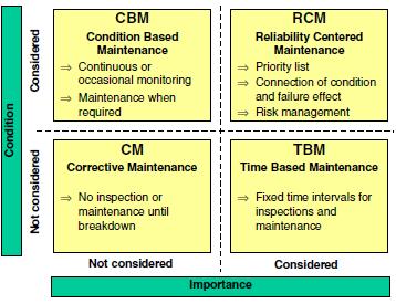
The main factor is to increase asset life cycle is the efficient maintenance. it is classified base on two aspect conditions of asset and maintenance importance as shown i n Fig 2. The most popular type is Time Based Maintenance (TBM), despite TBM is widespread The Reliability Centered Maintenance (RCM) for the ageing assets is used for many organizations even it is not documented on its procedures. Illustrated to increasing maintenance frequency for the asset has poor performance. RCM NGSA has been changing its maintenance strategy to be RCM to develop the assets dependability and optimize the resources and minim ize the OPEX.
Additionally, the condition base maintenance and corrective maintenance for HV [7] and distributions grid respectively, used in some companies as a maintenance strategy . Although it is used to reduce costs, the consequences for these applied are more than what achieving from the cost reductions
2. Risk Management:
Asset Risk Management is one of the three pillars of asset management [10]. It is providing a clear view for the company, have it to continue spending on the repair/ refurbish or must decide, and which kind of decision is required, the risk management plays an important role in this aspect. The NGSA adopted the Consequences and probability module as Fig.3. The consequences of its, including the compliance, the safety of assets and human, energy lost reliability, reputation, and financial costs [11]. The outcome from this module after taking the happened risk probability and its consequences shall classify all assets in different categories as shown in fig.1 Based on that the proposed solution submitted and reassessment to investigate the solution validations.
Consequence
Probability
V. RESULTS AND ANALYSIS
A. Input data:
It has applied three case studies, two of them on high voltage overhead transmission lines, and one case specified on the med ium voltage switchgear as shown in Table.1

B.
assets:
The results show expenses on the case studies assets of Line A, Line B and SWG 1 have fluctuated which means time base maintenance is not used mainly. The equipment condition is one of the main factors as displays in the charts the relation between OPEX and KPIs.
The transmission lines have almost the same behaviors as graph form. It is noted OPEX increased /decreased parallels with forced outages cost in several years such as 2011 in Line A and 2018 in Line B. However, the scale measure is different in Fig.4 and Fig 5 due to the high amount of expenses in Line B, especially refurbish what was happed in 2011.
The SWG 1 has been the liner relation between high expenses outages cost as shown in Fig.6, that due to the asset was on the stage called on Markov based model "poor" Referring to Fig.1 it has two options, whether to continue spending o n refurbishing or replace. Therefore, the decision -maker chooses the replace option in 2016 after OPEX increased continuously.
C. KPIs for the case studies assets:
In this part, it will show the technical KPIs for every case study from 2011 -2019, which included on the chart for SAID and another chart for the remaining KPIs such as SAIFI, MAIFI, FOFI, and No. of interruptions.
The Line A case study shows how the improvement on the KPI that related to the duration as SAIDI concurrently with the measure investing to repair the asset in 2011 as shown in Fig.7 and Fig.4. However, it is shows enhancements it's on four years from 2012-2015, this perfection was not sustainable for the years 2016 -2019.
On the other hand, it is clear from the Fig.8 the expenses have reinforcement the asset has a temporary improvement on interruption frequency KPIs as noted o n 2013, although, the investment on the line on 2018, Its positive results began to appear for all KPIs, It could be the root cause of the failures has been repaired or replace it.
The second case study for Line B has massive expenses in 2011, although of that, its KPI has not improved as expected as shown in Fig9 and 10, compared with its expenses (Fig.5) and Line A KPIs. The charts show fluctuated behavior; therefore, it is not healthy to confirm the improvement in some years which could temporary enhancement.
In the final case study in this paper, it was on switchgear 13.8 kV, this is the ideal application of effective maintenance with getting excellent outcomes from expenses from what was invested in. It is clear from Fig.11 and Fig.12 compared with Fig.6
D. Asset Risk Management:
Asset risk management (ARM) of the three cases has been applied to varying degrees. Table 2 shows the asset risk register included two aspects which are consequences and probabilities. It evaluates the consequences out 25 included compliances, the safety of assets and humans, energy lost reliabil ity, reputation, and financial cost. The formulation no (6) has been used. The probabilities evaluation was out of 5.
It is clear from table 2, the asset response to the repaired/ refurbish has reflected on the asset risk register rates. However, the ARM is the main input factor of asset management that can be decided, manage, and monitor the asset on the optimal way until the disposal decision is made.
VI. CONCLUSION AND RECOMMENDATION
The objective of this paper is to investigate the asset management applications in three case studies using Markov based model. The results of that were different outcomes of these cases have been noted an d analyzed.
It demonstrates the return on expenditures depends on asset condition and the kind of action taken to reinforce the equipment. It has been proven in the line A case, it has a good return on the duration of the interpretation KPI, with a modest impact on frequencies interpretation after 2011 repairing. However, the 2018 reinforcement has a massive improvement on all KPIs. The efficacious rehabilitation has been shoes on SWG 1 case.
However, continence maintenance and repairing not always the ideal solution as substantiated online B. The asset management could choose the optimal solution which even the disposal of the assets could be the optimal option in some cases. Alternative options such as change the network configurations or replace the assets sometimes are feasible and useful inst ead of continuing to growl OPEX of the organization.
To sum up, it is recommended to make disposal/repaired decisions based on optimization between expenditures and KPIs affect feeding on historical data. Asset risk management shall be a consideration as one of the main factors to determine to continue expenses on ageing assets or disposal
The reliably centered maintenance is the suitable type for the ageing asset due to kept and monitor the asset -based its outcomes. However, the assets KPIs is advisable to include it as the main factors for RCM and the kind of repairing/action taken required.
For further studies, the feasibility study of the ageing case studies asset using CAPEX, OPEX, and other factors to formulate the optimal time to dispose of/replace the assets.
VII. REFERENCES
[1] Schneider, J., Gaul, A., Neumann, C., Hogräfer, J., Wellßow, W., Schwan, M. and Schnettler, A., “Asset management techniques” International Journal of Electrical Power & Energy Systems, 28(9), pp.643-654, 2006
[2] CIGRE Technical Brochure 367 “Asset Management Performance Benchmarking”, Working group C1.11,2008
[3] Electricity & Cogeneration Regulatory Authority “ECRA Régulations Codes”, Ecra.gov.sa ,2020
[4] Kurtz, C. et al “Managing Aged Transformers” Transmission and Distribution World , July 1, 2005
[5] Gaul, A. J. Nilges, J., Nockmann, E., Thurlby, R.”Strategic Investment Planning” CIRED 2005, Turin 6-9 June 2005, session 6
[6] Gilpin, A. and P, –., 2020. "Strategic Asset Management for physical infrastructure: Run, Repair, Refurbish, Replace ” Master. The University of Sierra Leone , 2019
[7] Study Committee 37 “Ageing of the System. Impact on Planning” CIGRE Technical Brochure 176, 2000
[8] CIGRE Technical Brochure 309 “Asset management of transmission systems and associated CIGRE activities” Working Group C1.1, 2006
[9] Singh C, Schwan M, Wellssow WH. “Reliability in liberalized electric power markets- from analysis to risk management -survey paper” 14th Power system computation conference PSCC, 2002, Sevilla.
[10] Schneeweis, Thomas, Schneeweis, Thomas, Crowder, Garry B, & Kazemi, Hossein. “The new science of asset allocation” 1st ed., Wiley Finance. New York, 2010.
[11] Schoeman, J.S, & Vlok, P.J. “The possible influence of risk management, forecasting, and personnel training in physical asset management ”, South African Journal of Industrial Engineering, 25(2), 96-104, 2014
Assessment Of Recycled Asphalt Concrete Flexibility
Saad Issa Sarsam*1 Mohammed Chaloob Saleem 2
1 Professor, Department of Civil Engineering, University of Baghdad, Iraq *Corresponding author, email: saadisasarsam@coeng.uobaghdad.edu.iq
2Department of Civil Engineering, University of Baghdad, Iraq email: engsaad09@yahoo.com
Abstract
Utilizing reclaimed asphalt pavement (RAP) in new asphalt mixtures has increased in recent years because of its economic and environmental benefits. The flexibility of recycled asphalt concrete (with cutback and emulsion) in terms of resilient modulus (Mr), rutting resistance, and permanent microstrain have been investigated in this work. Cylindrical specimens of 102 mm in diameter and 102 mm in height have been prepared from the recycled mixture after the short -term aging process. Specimens were subjected to 1200 repeated compressive stresses at (25) ºC. The vertical permanent microstrain was monitored through video capture. It was concluded that RAP mixture can hold the applied loading with minimal permanent deformation as compared to the recycled mixtures . The resilient modulus is lower by (24 and 39) % for mixes recycled with cutback and emulsion respectively as compared to that of RAP. The rate of strain (slope) increases by 11 % and 4 % when cutback and emulsion were implemented as recycling agents respectively as compared to that for RAP mixture.
Keywords: Recycling; Asphalt Concrete; Rutting; Resilient Modulus; Permanent strain
1 Introduction
The challenge facing road engineers is to develop a sustainable asphalt mixture that reduces pavement system failure by developing new road materials and new methods of road construction and maintenance, [1]. Progress in road material science has focused on aged and waste materials, such as RAP, likely because of the continued availability of low-cost materials and due to the functional design of asphalt pavements. Recycling can provide the RAP, which is an important economical saving, RAP is usually considered to be a cost-effective pavement construction material that is placed in the pavement at increasing percentages, [2]. Many researchers had indicated the economic benefits of recycling, [3]. construction and reconstruction of road pavements imply a considerable consumption of valuable and non -renewable natural resources and the component materials of asphalt mixtures, [4]. The properties of the recycled mixture are believed to be mainly influenced by the aged, reclaimed asphalt pavement (RAP) binder properties, and the amount of RAP in the mixture, [5]. Asphalt binder loses many of its oil components during construction and service resulting in a high proportion of asphaltenes in the blend, wh ich leads to increased stiffness and viscosity of the binder and decreased ductility, making the binder hard and brittle, [6]. To recycle this hard and brittle aged pavement, the asphalt must be returned or changed to have the rheological properties of the original asphalt. This transformation is completed by adding liquid additives to the mixture being recycled, these additives have been called recycling agents or softening agents, [7]. Rejuvenating emulsions are normally used, containing oils that reduce the viscosity of aged asphalt cement, thus improving the adhesion and cohesion properties, as well as the flexibility of the binder. In addition, rejuvenators can penetrate the voids of the pavement, filling them and minimizing binder oxidation, [8]. The r utting resistance of recycled mixtures was studied by [9]. Four mixtures with RAP percentages of 0%, 15%, 30% and 50%, were tested. Results obtained from the wheel tracking test indicated that RAP mixtures have very similar rut depth values at the end of t he test when calculated between cycles 5000 and 10,000 which means that the presence of RAP in mixtures provides greater resistance to rutting. laboratory investigation of permanent deformation characteristics of asphalt concrete mixes containing reclaimed materials was presented by [10]. The permanent deformation characteristics of asphalt concrete with and without reclaimed materials were evaluated in the laboratory using the Repeated Load Axial Test and Wheel Tracking Test at a range of test temperatures. Test results showed that the asphalt concrete prepared using reclaimed materials such as waste plastic and Reclaimed Asphalt Pavement (RAP) was more resistant to permanent deformation over a range of temperatures. The use of resilient modulus testing to compare mixtures compacted with only virgin materials to those compacted with varying amounts of RAP was conducted by [11]. Resilient modulus testing was conducted in accordance with ASTM D 4123-82. The test was performed at 0.33, 0.5, and 1 Hz. In a 1 -Hz test, the applied cycles consisted of a 0.1-second load followed by a 0.9-second rest period. It was concluded that the resilient modulus rapidly decreases with increasing temperature. This is due to the softening of the asphalt binder as the temperature increases
In this investigation, the variation in the flexibility of the RAP and recycled asphalt concrete pavement (with cutback and emulsion) in terms of resilient modulus (Mr), rutting resistance, and permanent microstrain have been investigated.
2 Material Characteristics
2.1 Aged Materials
The reclaimed asphalt mixture was obtained by the rubblization of the binder course layer of asphalt concrete of the highway in the province of Babylon. This highway heavily deteriorated with various cracks and ruts existing on the surface. The reclaimed asphalt mixture obtained was assured to be free from deleterious substa nces and loam that gathered on the top surface. The reclaimed mixture was heated, combined , and reduced to testing size as per AASHTO, [12]; a representative sample was subjected to an Ignition test according to AASHTO T 308, [12] procedure to obtain binde r and filler content, gradation, and properties of aggregate. Table 1. Presents the properties of aged materials after the Ignition test.
1. Properties of Aged Materials after Ignition Test
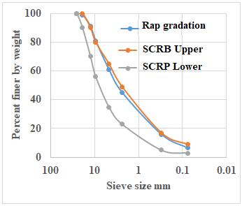
Gradation for the RAP obtained from the reclaimed mixture was determined; six samples have been selected randomly from the publication process of the material stack. These samples were subjected to an Ignition test to isolate binder from aggregate and then aggregate was sieved and separated to various sizes to calculate gradation for each sample. The differences between samples were to a minor extent, and the average gradation of the six samples obtained to be the old aggregate gradation is shown in Fig ure 1 which illustrates that the gradation of old (reclaimed) aggregate for the binder layer has slimly deviation with Specification limits of Roads and Bridge SCRB, [13].
2.2
Two types of liquid asphalt have been implemented as recycling agents based on the available literature, [1, 4, 5, 6, and 14]. They are medium-curing cutbacks and cationic emulsions
Medium curing cutback (MC-30) obtained from the Al-Dura refinery was adopted for recycling in this work. The properties are listed in Table 2.
2.4
Cationic emulsion obtained from ministry of industry and minerals was adopted for recycling in this work, the properties are listed in Table 3.
2.5 Recycling of RAP Mixture
The recycled mixture consists of 100 % reclaimed pavement RAP and a recycling agent mixed together at specified percentages according to the mixing ratio. First, RAP was heated to approximately 160º C and liquid asphalt was added to the heated RAP at the desired amount of 0.5% by weight of the mixture and mixed for two minutes until all mixture was visually coated with recycling agent as addressed by [1]. The recycled mixture was prepared using two types of liquid asphalt: medium curing cutback and cationic emulsion.
2.6 Preparation of Accelerated Short-Term Aged Recycled Mixture
The recycled mixture was heated to 130°C to become loose and then diffuses in shallow trays with 3cm thickness and subjected to accelerated aging by laying inside an oven at 135°C for 4 hours as per the Superpave procedure, [12, and 16]. The mix was stirred every 30 m inutes during the short-term aging to prevent the outside of the mixture from aging more than the inner side because of increased air exposure.
2.7 Preparation of Asphalt Concrete Specimens
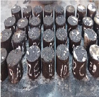
A cylindrical specimen of 102 mm in diameter and 102 mm in height has been prepared from the recycled mixture after the short-term aging process. The mold, spatula, and compaction hammer were heated on a hot plate to a temperature of 150º C. A piece of non -absorbent paper, cut to size, was placed in the bottom of the mo ld before the mixture was introduced. The asphalt mixture was placed in the preheated mold, and then it was spaded drastically with a heated spatula 15 times around the perimeter and 10 times around the interior. Another piece of non -absorbent paper cut to size was placed on top of the mix. The temperature of the mixture immediately prior to compaction temperature was 150ºC. The mold assembly was placed on the compaction pedestal and subjected to static compaction. The mixture was compressed at the top and bottom at a temperature of 150 °C under an initial load of 1Mpa to set the mixture versus the sides of the mold, after that the required load to achieve the target density of 2.372 gm/cm 3 was applied for two minutes and the specimen was left to cool at room temperature for 24 hours and then it was removed from the mold using the mechanical jack. Specimens were implemented for the Repeated compressive stresses test. Details of obtaining the target density were published elsewhere, [17]. Fig ure 2 exhibit part of the prepared cylindrical specimens.
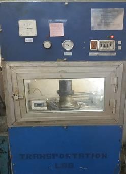
2.8 Testing of the specimens under repeated compressive stresses
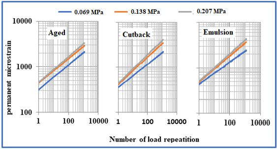
Asphalt concrete specimens were subjected to repeated compressive stresses in the pneumatic repeated load system PRLS. The axial repeated load was app lied to the specimen and the axial permanent deformation was measured. Compressive loading was applied in the form of a rectangular wave with a constant loading frequency of 60 cycles per minute and the loading sequence for each cycle is 0.1-sec load duration and 0.9 sec. Load repetitions were applied under constant three stress levels of (0.069, 0.138, and 0.207) MPa , while the testing temperatures of (25) ºC were implemented in the test.
Figure 3 exhibit the repeated compressive stress setup. The permanent vertical strain is measured as a function of the number of load applications recognizing the fact that the lower permanent strain is related to the lower sensitivity for rutting and corrugation. The ac cumulation of permanent and resilient strains (εp and εr) was monitored directly through continuous video capture, while the resilient modulus (Mr) was calculated using equations 1 and 2, [16 and18]. Specimens have been tested under three stress levels.
(1) where: σ: repeated diametral stress (N/mm²) t: the thickness of specimen (mm).
P: applied load (N) h: specimen diameter (mm).
(2)
Where: σ: repeated diametral stress (N/mm²). εr: vertical resilient strain (mm/mm).
Mr: resilient modulus (N/mm²).
3 Results and Discussion
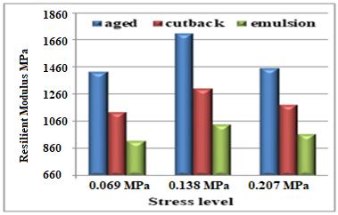
3.1 Effect of Recycling Agent Types and stress levels on Resilient Modulus (Mr)
Figure 4 exhibit the influence of the stress level on resilient modules for the aged and recycled mixture (cutback and emulsion) under compressive stress at 25 °C after 1200 load repetitions. The resilient modulus increases up to a stress level of 0.138 KPa, then decreases when the stress level increases to 0.207 MPa. The highest resilient modulus could be achieved at 0.138 MPa level of stress for all mixtures. This may be attribut ed to that the recycled mixture requirement of strength is suitable under the moderate traffic loading condition. A higher stress level of 0.207 MPa will possess extra tensile stresses which the mixture is unable to accommodate, then the resilient modulus is decreased. On the other hand, a lower stress level of 0.069 MPa will not exhibit a high impact on the resilient modulus. It can also be observed that the RAP mixture exhibits a resilient modulus of 171 MPa, while the recycled mixtures show lower resilient modulus by (24 and 39) % for mixes recycled with cutback and emulsion respectively as compared to that of the aged mixture. Such results agree with [16] work.
3.2 Effect of Recycling Agent Types and stress Levels on Resistance to Permanent Deformation under repeated compressive stress
Figure 5 shows the impact of stress level on the permanent deformation parameter of aged and recycled mixture with (cutback and emulsion) after 1200 load repetitions, it can be obser ved that while the stress level increases, the intercept value, and the slope increase as well for different mixtures. The rate of increase for RAP (aged) asphalt concrete is (37.5, and 45.3) % for 0.138 and 0.207 MPa stress levels as compared to that at 0 .069 MPa. For recycled mixture with (cutback), the rate of increases is (17, and 25) % as compared to that at 0.069 MPa.
For recycled mixture with (emulsion), the rate of increases is (12, and 17) % as compared to that at 0.069 MPa. The rate of change in slope value is different for different stress levels and different mixtures. At a moderate stress level of 0.138 MPa, the recycled mixture with cutback asphalt shows a lower intercept value by 2 % as compared to that of RAP mixture, while the recycled mixture with emulsion exhibit a higher intercept value by 14 % as compared to an of RAP mixture. On the other hand, the rate of strain (slope) increases by 11 % and 4 % when cutback and emulsion were used as recycling agents respectively as compared to that for RAP mixture. this may be attributed to the more flexible nature of recycled asphalt concrete as compared to RAP. Such test results agree with [16 and 18] work.
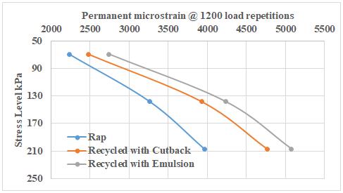
3.3
Figure 6 exhibits the rutting performance of various asphalt concrete mixtures; it can be observed that the stiffer RAP mixture can hold the applied loading with minimal permanent deformation as compared to the recycled mixtures. At a high-stress level of 207 kPa, the permanent strain increases by (20 and 28) % for recycled mixtures wit h cutback and emulsion respectively as compared to RAP mixture. Table 4 demonstrates the mathematical models regarding the resistance to rutting of asphalt concrete where (Y) represent the permanent deformation (microstrain) and (X) denotes the load repetitions. A similar rutting trend was reported by [14].
4 Conclusions
Based on the testing program, the following conclusions could be drawn:
1- The resilient modulus is lower by (24 and 39) % for mixes recycled with cutback and emulsion respectively as compared to that of RAP (aged) mixture at a moderate stress level of 0.138 MPa.
2- The resilient modulus increases up to a stress level of 0.138 KPa, then decreases when the stress level increases to 0.207 MPa. The highest resilient modulus could be achieved at 0.138 MPa level of stress for all mixtures.
3- At a moderate stress level of 0.138 MPa, the recycled mixture with cutback asphalt shows a lower intercept value by 2 % as compared to that of RAP mixture, while the recycled mixture with emulsion exhibit a higher intercept value by 14 % as compared to to that of RAP mixture.
4- The rate of strain (slope) increases by 11 % and 4 % when cutback and emulsion were implemented as recycling agents respectively as compared to that for RAP mixture.
References
[1] Sarsam S. “A study of aging and recycling of Asphalt Concrete pavement. University of Sharjah ” , Journal of pure and applied Sciences, Sharjah UAE Vol.4 No.2 June- P79-94. (2007)
[2] B. Colbert, and You, Z., “The Determination of Mechanical Performance of Laboratory Produced Hot Mix Asphalt Mixtures Using Controlled RAP and Virgin Aggregate Size Fractions ” , Construction and Building Materials, Vol. 26, pp. 655- 662. (2012).
[3] NCHRP Synthesis 495. “Use of Reclaimed Asphalt Pavement and Recycled Asphalt Shingles in Asphalt Mixtures. A Synthesis of Highway Practice” National Cooperative Highway Research Program. Project 20-05, Topic, 46-05. (2016).
[4] I. Al-Qadi, E Seifi, M., and Carpenter, S., “Reclaimed Asphalt Pavement A Literature Review” , Report No. FHWAICT-07-001, Illinois Center for Transportation , Rantoul, IL. (2007)
[5] P. S. Kandhal, and Mallick R.B., “Pavement Recycling Guidelines for State and Local Governments Participant's Reference Book” , Report No. FHWA-SA-98-042, Federal Highway Administration Office of Engineering. (1997).
[6] A. Copeland, “Reclaimed Asphalt Pavement in Asphalt Mixtures: State of the Practice” , Report No. FHWA-HRT-11021, Report Date April (2011)
[7] H. M. Silva, Oliveira J.R.M., and Jesus, C.M.G., “Are totally recycled hot mix asphalts a sustainable alternative for road paving?” Resources, Conservation and Recycling , Vol. 60, PP. 38-48. (2012).
[8] K. A. O’Sullivan, “Rejuvenation of Reclaimed Asphalt Pavement (RAP) in Hot Mix Asphalt Recycling with High RAP Content” , M.Sc. thesis, Worcester Polytechnic Institute. (2011).
[9] R. Miro, Valdés, G., Martinez, A., Segura, P., Rodriguez, C. , “Evaluation of High Modulus Mixture Behavior with High Reclaimed Asphalt Pavement (RAP) Percentages for Sustainable Road Construction ” , Construction and Building Materials, Vol. 25, PP. 3854–3862. (2011).
[10] I. Aschuri, Woodward D. and Woodside A., “Permanent deformation characteristics of asphalt concrete containing reclaimed materials” , International Society for Maintenance and Rehabilitation of Transportation Infrastructure; technical report, Transportation Research Board. (2009).
[11] M. S. Sondag, Chadbourn, B.A., and Drescher, A., “Investigation of Recycled Asphalt Pavement (RAP) Mixtures ” , Report No. MN/RC – 2002-15, Minnesota Department of Transportation. (2002).
[12] AASHTO. “Standard Specification for Transportation Materials and Methods of Sampling and Testing” , American Association of State Highway and Transportation Officials , 14th Edition, Part II, Washington, D.C. (2013).
[13] SCRB, “General Specification for Roads and Bridges, Section R/9 Hot -Mix Asphalt Concrete Pavement”, Revised Edition, State Corporation of Roads and Bridges, Ministry of Housing and Construction , Republic of Iraq. (2003).
[14] S. I. Sarsam, AL-Zubaidi I. “Resistance to Deformation under Repeated Loading of Aged and Recycled Sustainable Pavement” American Journal of Civil and Structural Engineering , (AJCSE), Vol. 1(2), April Sciknow Publications Ltd. USA. p34-39. (2014).
[15] ASTM. “Road and Paving Material, Vehicle-Pavement System” American Society for Testing and Materials. Annual Book of ASTM Standards, Vol.04.03 (2009).
[16] S. I. Sarsam and AL-Shujairy A. “Influence of recycling agent type on resilient modules and rutting resistance of asphalt concrete pavement” . Applied Research Journal, ARJ . Vol.2, Issue, 1, January, pp.10 -18. (2016).
[17] M. C. Saleem “Influence of Liquid Asphalt Additives on the Properties of Recycled Asphalt Concrete ” . MSc. Thesis, College of Engineering, University of Baghdad, (2018)
[18] S. I. Sarsam and AL-Janabi I. “Assessing Shear and Compressive Strength of Reclaimed Asp halt Concrete” International Journal of Scientific Research in Knowledge, (IJSRK) 2(8), pp. 352-361. (2014).
DIGITAL TWIN CONCEPT AND ITS APPLICATION TO POWER GRID – REMOTE ACCESSING AND MAINTENANCE OF PROTECTION SYSTEMS SCADA SAS AND TELECOM SYSTEMS IN POWER ENTERPRISES
Venkatasamy Ramesh*
Functional consultant & Former Consultant at National Grid SA, India.
venkatesh.engg.consultants@gmail.com
Abstract:
A Digital Twin (DT) is a digital replica of a physical object. In this presen tation, Digital twins are currently mostly used in power systems for visualization or to bring data together, validate software or extract data and do maintenance remotely. We did this DT to enable the remote accessing of RTUs (Remote Terminal Units), SAS (Substation Automation Systems), and protection Systems, and validate requirements on the digital model Unlike other regions in (Name of the organization not mentioned here) , the southern Telecom &SCADA team was in the field of implementing the Digital Twin technology as continuous improvement works during 2009 -2010, which was named as “Benefits Oriented Zero Cost projects in Communication Automation Technologies” (hereafter BOPCAS). Communication Automation was a rapidly growing area of technology that is seeing growing interest within the power system. The Zero cost projects were the real history projects which were implemented in electric power systems have a wide impact on the prevention of blackouts, less maintenance cost enables the Control center to take quick decision making in the operation and maintenance field. In earlier years there were no such Digital Twin technologies provided by the project execution, hence the power system network has faced lots of problems and delays in execution in operation, and maintenance. Today the world is facing an economic crisis and power system problems, SCADA & Communication team plays an important role in minimizing the impact of widespread power system Disturbances by having implemented the Benefits Oriented Zero Cost projects since 2009. The purpose of this paper locates the notion of technological revolutions in the Communicat ion Automation Systems in southern power system effort to understand innovation an d to identify the regularities and discontinuities in the process of manufacturers’ design. All the ambiguities of the Manufacturing design stage were corrected by the team and are up to the standards and operational with good results to date. It fulfills the patterns observed in the evolution of Technical change and the interrelations with the context that shape the rhythm and direction of innovation. On this basis, it defines technological revolutions and examines their structure and the role that they play in rejuvenating the whole system through the application of the accompanying techno -economic paradigm. All the Zero Cost Projects( no money spent for the materials, utilized the old materials ) which have been implemented in the Najran power system are without any additional equipment, materials , and additional Project Costs which helps the power systems in Najran to tackle the various techno-economic problems. It renders trust worth Services and time-proven systems to Consumers, operation and Control Sections, and the Transmission section of Najran.
Key Words: Millions Cost to Zero Cost Projects - Reduces Income loss - No maintenance cost - Serves as Backbone to Master Station
1 Introduction
A digital twin is a virtual representation of a real -world object or system. Such a digital carbon copy gives developers many interesting opportunities. For instance, they can test their software, and they can run all kinds of simulations and what-if scenarios on the digital twin long before the physical system is available. This way they can drastically reduce development time and boost first-time right deployment. In this talk, we give a definition of ‘being a twin’ using testing equivalences and conformance relations. We then give methodologies to actual create requirements and automatically validate these requirements using model -based testing. We apply our definition and methodology to a factory model representative of typical systems used and developed by our customers. Unlike other regions in the world, the Najran region from the south of electricity sectors has implemented many historical Zero cost projects in the electricity sectors in HV, LV Substations, and Control centers in terms of low-income loss to the distribution department and ensuring uninterrupted power to 150,0000 Consumers, the introduction of Zero cost projects, modernization and a new approach for operation and maintenance. All of the Projects which have been implemented are based on the recycled process which in turn improves the economic performance of the running and maintenance costs of the power system. This Zero cost technology projects are known as “Najran Blooms with Zero Cost Projects” or “Million costs to Zero cost Projects” has wide positive effects on the Key Performance Indices (KPIs) in the Najran region. In addition to the Zero Cost Projects, Najran National Grid is launching various precautionary measures to the Communication systems for fail Safe operation by implementing various modifications and designs to suit the existing systems for upgrading in an efficient manner.
In such Zero Cost Projects, Najran National Grid will implement these projects in other inter -regional Communication Systems in an efficient manner. Three Major dimensions can be identified in such a project (1) Technical dimensions, (2) Economical dimensions, and (3) Safe operation dimensions Although the Najran National Grid team had devised many (7) Zero Cost Projects, only five topics will be introduced in this paper.
1. Remote Reset of RTUs in HV & LV Stations
2. Remote Access and Remote Configuration of RTUs
3. Continuous Monitoring of UPS and DC System ( 125 & 48 V DC ) system voltage at Control Centres from remote Stations HV & LV
4. Online monitoring of Fibre Splicing
5. Integration of Radio systems with Fibre network
All of the above Projects that we designed, engineered, and implemented in Najran wer e with Zero Cost; no money has been spent from the National Grid department’s budget. All the projects are operational in the southern region., all the materials and equipment have been used in these projects are based on the recycling technique, hence no additional cost for the projects and achieved the goals in a short time [1][3]
2 Scalable Architecture
2.1 Remote Reset of RTUs (Remote Terminal Units) – Zero Cost Project for 14 Substations in Najran:
RTUs in Remote Substations are sometimes subject to Hang up (Sleep mode or Image Mode ) that time if any 132 KV line feeders or 33 KV Feeders or 13.8 KV feeders trip, the Control centre tries to Close the CB, but this Command cannot reach to that Circuit Breaker due to that RTU is in Hang up condition and. RTU needs to be reset manually by any SCADA Personnel traveling to that remote S/S and then the Control centre can give close Commands to those CBs. [2][3]
To overcome such above problems, Telecom Group had designed a new Zero Cost mec hanism to reset the particular remote Station RTU from the southern control canter Desk; this facility is available in Najran since 2009. To reset the RTUs in all Substations in the southern Area, Control Centre personnel shall do it by themselves, with no need for assistance from SCADA Personnel for r e-setting the RTU. Reset of RTU facility in Najran area gives trust worth Services and time-proven systems to the Consumer, Operation, and Control Sections of the electricity sector in southern regions.
All materials used in this project were utilized by the recycling process, hence no money was spent from SEC budget, with available materials in the Southern electricity sector for this Remote Reset of RTUs mechanism implemented within one month in 14 Substation’s RTUs in the southern Area. The control centre can access to reset the remote substation RTUs from the Control centre table and hence providing flexibility to the Control centre operations
When the RTU is in sleep mode, the remote reset of RTUs mechanism is helpful to the distribution maintenance team, Transmission line maintenance team , and Control centre when there is any 13.8 KV poles getting fire, also any foreign object (polythene papers or clothes , etc) touching or hanging on HV transmission lines and need to open the CBs at Substations, the CC shall to press the related reset button for the substation to reset the RTU which is in sleep mode, within 2 minutes the RTU will be in service to open the CBs [1][4]
2.2 Remote Reset of RTUs Mechanism in power system
To reset the RTUs in Remote Substations in Najran, Just press the button in the Key telephone button the command will be sent to that particular RTU through MDFOTE and DPLC links and then the RTU will rest within 2 minutes and the RTU becomes operational state without the involvement of SCADA & Telecom. Staff and network operators. Each station RTU reset is independent of the other All the RTU Wirings are safe and secured properly, ensuring more reliability of RTUs operation due to the presence of Remote reset of RTUs from the Control Centre Screen and Communication room as well.
2.3 RTU Hang Up (Sleep Mode & Image Mode) Reasons.
RTUs or any electronic equipment which operates with a high baud rate are sometimes subject to hang-up (sleep mode or image mode). Hang up of electronic equipment due to the following reasons [5][7].
a. Mismatch levels in MDFOTE link b. Mismatch level in DPLC link c. Hold Over situation in MDFOTE d. Error in serial Communication ports of RTU e. Command Interruption f. Error in Data module g. Any other command in progress h. Poor connections


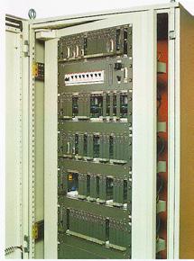
2.4 RTU 560 CPU and Its Racks.
RTU modules are operating with 24 V DC and 5 V DC Voltages; CPU module is with flash memory and operates with different Data Speed as set by the maintenance personnel by RTU Software too l. In Najran all the 132 KV RTUs are operating with a data speed of 19 200 b/s [3]
2.5 Merits of Remote Reset of RTUs in Najran.
1. No need to travel to the remote Substation to reset the RTU [1]
2. No need Operator to travel to the Substation to close the CB when RTU hangs up during Day or Night time.
3. Cuts down Time
4. Cuts loss of revenue to electricity departments
5. Ensures RTUs reliability and thus maintains Reliable Electricity to Customers

6. Remote reset of RTU facilitates the CC dispatcher to reset the particular RTU in the Substation by pressing the button in the Telephone set in any kind of emergency situation, Reset mechanism is kept at the control centre
7. Reduces traveling time & traveling expenditure
8. Reduces Operational Costs
2.6 Remote Access and Remote Configuration of RTUs , SASs, and Protection Systems
This facility is available only in this electricity sector, modification of any Data in a remote Substation’s RTU normally a maintenance person needs to travel to that substation, but in Najran no need to travel to the remote substations, all the Data modification shall be done at Najran CPS Communication Room itself. Also , this facility serves as the backbone of the Master station computers[1][2].
2.7 Remote Access and Remote Configuration of RTUs
Any modification or addition of Data in RTUs in a Remote substation needs a SCADA staff to travel to that Substation and then perform the Data modification with Laptop, also needs the Operator to be present till the RTU becomes in operation mode.
As an example S/S E RTU in the southern Area if it needs configuration change, SCADA Staff need to travel from headquarters to S/S E i.e. 300 Kms away from CC After implementing this facility no need to travel to any of the 132 KV S/Ss for data modification [5]
2.8 Serves as the backbone
In case of the Master station, the computer fails, an inoperative stage arises or any emergency at that time this Remote Access facility will perform all operations such as Command execution, back indications, alarms , and measurements shall be collected from the remote Substations. It serves as the backbone mechanism for the Master station. RTU Training for maintenance employees shall be performed with different station RTUs in one place at a reduced cost. A behavioral study of different RTUs shall be carried out[1]
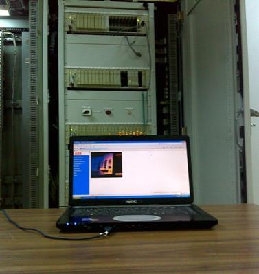
2.9 Accessing RTU Locally at Substation
Here the Picture shows that the RTU is being accessed locally at Substation Need to travel to that Substation & network Operator is required to close the tripped CBs while uploading the RTU
3. Digital Twin design and execution
3.1 Accessing the RTU, SAS, Protection systems, DC systems r emotely from Control centre
Here the Flow diagram shows that the RTUs, SAS system, Protection systems, and DC system 125&48V dc shall be accessed through related telecom panels and brought to the control centre screen. From the Control centre all the downloading/uploading of data and creation and modification of data for all the utilities can be done from the control centre. Normally to download/upload data in above said asset ut ilities need to travel to each substation, but after implementing the Digital Twin facilities it is very easy from the control centre building to view and modify the data.

The HMI ports of RTUs, SAS, protection panels , and DC systems shall be carefully interfaced at each substation E, D, C, B, A, and CC with suitable connections[3] [4]
3.2 RTU remote Accessing
RTU Process signal flow diagram shows how the RTU 560 remote accessing and how the signals such as commands, indications, alarms, and measurements are processed from the Substation’s Switch Gears
3.3 Merits of Remote Access and remote Configuration of RTUs ., SAS, Protection systems, and DC systems
a. No travel expenditure b. Cuts downtime. c. No additional manpower (operator or maintenance personnel). d. During a Blackout situation, this Digital Twin technology is very much useful to know the power system parameters from the Control center. e. Serves as the backbone of the Master station. If the Master Station Computer system fails or is in the inoperative stage that time this Remote Accessing for RTU will take care of the activities of the Master Station to open and close the switch gears f. Training for maintenance personnel shall be carried out with different station RTUs , SAS, protection systems, and DC systems in one place
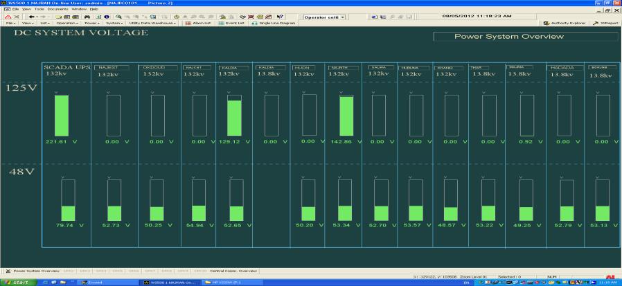
4 Continuous Monitoring of DC System Voltage at Control centers
The continual improvement of Telecom & SCADA, Group had implemented the project of monitoring 125 and 48 V DC System Voltage at the control center with old scrap materials, recycle process technique was followed with out spending any money from the electricity sector’s Budget
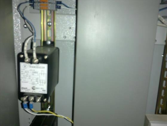
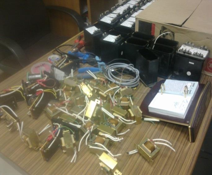
The improvement group completed this implementation of DC System Voltage Monitoring at the control center with Zero cost during 2009-2010. Earlier there was no such monito ring of the DC system Voltage at the control center, but now all the 132 KV S/Ss and 33 KV S/Ss have been implemented for the continuous monitoring of the DC system Voltage at the Control Centre screen. SCADA & Telecom Group used Scrap materials -Transducers, cables, and fixtures.
The old Voltage Transducers were suitably modified to comply with DC system voltage and tested for its accuracy and then installed at various substations and commun icated the voltage readings to the Control center. Now 125&48 DC voltage of all Substations, SCADA UPS were implemented at Control center. Old Transducers were with 0 -1mA which was not compatible with the new SCADA System, but SCADA & Telecom Group had done suitable by conversion in the configuration in all RTUs and made suitably and comply with SCADA systems without any additional cost and materials[7]
These Transducers were removed from the old SCADA System, checked for their accuracy and calibrated for their linear characteristics, and then installed for the DC system voltage monitoring in each substation. After the installation of transducers at each Substation several tests were carried out such as the discharge and recharge of battery banks and observing the linearity of the magnitude of DC voltages at the Control center Screen. All the results are satisfactory and up to the standards [7]
4.1 Continuous Monitoring of DC System Voltage from Remote Substations.
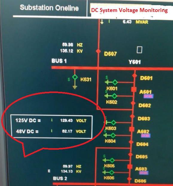
Earlier there was no monitoring facility for the DC system voltages to appear at LDC, but now 48 & 125 V DC Voltages of different Substations in Najran are appearing at LDC Najran screen.
Fig. 9 shows the dc system voltage levels from various substations (132 & 33 KV ) that were being monitored for 48 V, and 125 V dc systems. The provision also has been implemented to monitor the SCADA UPS system voltage at the Control center [1][7]
4.2. Worthiness of DC system & SCADA UPS System Voltag e Monitoring at Control Centre
a. During a Blackout situation the DC Voltage & SCADA UPS Voltage monitoring in different substations are helpful to the S/S maintenance team as well as to the Control centre dispatcher.
b. Assume the alarm card in RTU for Charger Alarms is defective or has no connection, that time this DC system Voltage monitoring at the Control centre is useful c. Any dip in power system voltage occurs that time study the DC system performance shall be known with time & date at the Control centre itself d. Automatic boost voltage function if it happened in DC system, then it will be known for Date & time e. Chargers having poor performance and poor voltage regulation characteristics shal l be easily known from the daily CC voltage log f. Anyoneone needs to know the present level of DC voltage, no need to tra vel to the Substation which is 400 or more Km distance, just visit and request the Control centre dispatcher for the present status of DC system in a particular Substation g. Comparison of different DC systems Voltage in different Substation collectively at one place at Control Centre, no need to travel different substations. h. Cuts Travelling time & traveling expenditure drastically i. If both chargers are having problems due to Ac input failure, that time we will come to know the Voltage level of that DC system, Voltage level is enough to withstand up to 10 hours or 5 hours so that the DC system maintenance personnel will rush to the Substation according to the Voltage level indicated at LDC screen j. Control centre dispatcher and dc system maintenance teams relieve tension and they will be strong in psychologically too k. Daily Log shall be prepared at headquarters without visiting each Substation l. Behavioral study of DC system for continuous service
4.3. Remote Charging and Discharging of DC system is under progress :
The improvement team also studied the possible steps to implement the remote charging and discharging of the valve-regulated battery bank (maintenance-free battery bank ) in the power system. If this facility is to be implemented in the electricity sector, then no need to travel or go to the remote substations for discharging and recharging the battery banks. This is applicable only to valve-regulated battery banks. Maintenance of DC system group shall able to give command from the headquarters to open command to the chargers to switch off the AC input source to the rectifier while discharging the voltage level s shall be obtained from the Control centre ( if already implemented the remote monitoring of DC systems ) screen. After discharging with a safe operating voltage level, the close command will be executed by the DC system maintenance personnel and then the rectifier will b e in service and voltage will be monitored continuously at the Control centre screen.
5 Strategic Decision
5.1 Plugging Loopholes in +48 V grounded communication systems
All the SCADA & Communication equipment in the southern area was free from circulation currents from the Substation ground system by having implemented the separate ground system for the Communication system. Also all Substations we have removed the shield wire of the Control & signal cables at the Switch gears panels side and have an earth connection at the communication equipment side. This ensures that the communication equipment such as RTU, MDFOTE, DPLC, SDH, and DPABX systems are free from circulation currents and hence the operation of all SCADA & Telecom equipment are in safe environments at Najran. All the voice circuits MDF & E1 circuits were equipped with suitable protectors to protect against the surge in the networks
EFFECTS OF UN CLEARED E/FAULT CURRENTS ON COMMUNICATION SYSTEMS WITH +48 V GROUNDED
Un - Cleared E/F Current arises due to 1. NO DC for tripping .
2. Relay may inoperative state .
3. Mechanical problem of CB

RTU Signal Cables and command cables are earthed , Shiled wires are with +48 V CB
O/G Cable Assume this cable has earth fault and CB not tripped , hence un Cleared E/F current circulate through Hardware metalllic contacts and cable cores
HOW COMMUNICATION EQUIPMENTS GETTING AFFECTED WITH CIRCULATION CURRENTS IN SUBSTATIONS
When there is a Circulating current occur in any Substation and if it is persisting for long time say 1 to 3 minutes , the circulating current may flow in RTU ,DPLC and FOX cables cores and reach to the cabinets of RTU , DPLC and FOX., In RTU560 the Modules 23BE21/23 are having filed contact voltage as +48 V , Since the filed contact Voltage is positive ground , the Circulation currents with high magnitude may enter inside the 23BE21 modules according to the effective resistance of 23BE21 Modules and damage the complete 23BE21 modules .
1. RTU-560 - 23BE21/23 modules may fail , if the circulation current magnitude is high the other modules 23AE21 , 23BA22 7 23 Ba20 may also fail
2. FOX - 515 - SUB-H module is prone to damage due the Telephone line inside the Cable ttrench / cable duct due to circulation current in S/S
3. DPLC -640- Power supply module may fail , DPLC balancing transformer and HF Hybrid may fail
HOW TO AVOID THE COMMUNICATION EQUIPMENTS FAIL FROM CIRCULATION CURRENTS FROM SUBSTATION
1. Implement separate Ground system with MGB for Communication equipments , No connection with Substation ground system
2. All the cables of RTU , FOX , DPLC , DPABX , SDH etc - The ground wires shall be earthed at communication cabinets only , other end no need .
Fig.11. Effects of Circulation currents on +48 V grounded Communication Systems
5.2 Command execution Successful Alarms: Whenever Control Centres execute a command either open or close the CB in any substations in the Najran area, that time if any interlock in force or local /Remote switch is in local position or no 125 V DC , such co nditions will not be permissive for the successful com mands up to the Switch gears
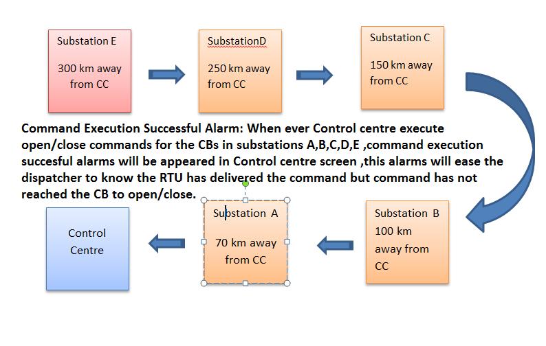
When the command is not successful, the Control Centres immediately inform the SCADA & Communication crew that the command was not successful to open or close the CB in the substation and an abnormality report will be issued to SCADA & Communication crew even if the closing and opening of CB problems which are not related to the SCADA system. To overcome these problems for SCADA & Communication crew, in Najran we have implemented a feedback signal for each command executed by RTU, this feedback signal will be disp layed at the Control Centre screen saying that the command executed by RTU was successful. This Command successful alarm in Najran relieves the SCADA & Telecom crew and also the Control Centre directly calls the substation crew to troubleshoot the control circuits of the CB. Such facilities in the southern electricity sector save in troubleshooting time
All the auto voltage (110-220 V) operating communication equipment such as the Radio system, ADAS system, and Chargers were connected with a 110 V source as safe operating voltage, in case any surge voltage occurs in the power source that will not affect electronic modules due to more reserve in voltage tolerance up to 220 V.
Double-stage fuse protection for Radio Base and repeater stations: in case any hi gh voltage if it comes in low voltage distribution circuits, this high voltage will damage the electronic modules with successive stages, to avoid such damage Najran maintenance team has introduced one more fuse circuit which is outside the Radio equipment as a fail-safe system
RADIO Station Ground Connection: All the Radio Station ground connections were not mixed with the ground ( MGB ) from the tower ground connection due to the lightning stroke from the antenna (built -in self-lightening arrestor ) cable should not reach the Radio station and affecting the power supply modules of Radio station .
6 Conclusions
CAS (Communication Automation Systems) whatever facilities are not covered in the Substation Project by the contractors and which cannot be designed by the manufacturers are modified and designed by Najran SCADA & Telecom. Team with zero cost and achieved goals for the beneficial use of electricity sectors. After implementing these Communication Automation Facilities Najran had not faced any Abnormalities due to RTUs in all S/S with the Presence of mechanism a) Remote reset of RTUs from the Control center’s table b). Remote configuration of RTUs and c). remote configuration of Protection systems d). Remote monitoring of DC system voltages
Above mentioned Zero cost project’s effective mech anism has drastically null the emergency works and hence no additional expenditure also these Digital Twin facilities are much useful to the electricity sectors , especially in the crucial situations of COVID19 .
The maintenance cost and running costs have been drastically reduced since 2009. Now Najran is stepping into the 4th year for achievement in NO abnormalities, NO Overtime, and NO maintenance cost. SCADA & Telecom Group did other four Zero Cost Projects, but due to the limitation of presentation rules those projects have not been mentioned in this Paper [5][6]
7 Acknowledgement
I sincerely thank my academic advisor and thesis Dr. N. Nanda Gopal, technical expert, and Director Eng. Fareed Al Asmari, Department Manager- National Grid south, KSA for his guidance and support throughout the preparation of this paper. Also, I am very thankful to Eng. Abdul Mohsin Ali Al Garni, Divisional Manager, SCADA & Communication South, KSA for their support in the preparation of this paper.
References
[1] Mr. Hiromitsu Kumamoto & Ernest j. Henley – “Probabilistic risk Assessment and management for engineers and scientist” IEEE, Second Edition, the Year 1998
[2] Mr. Joseph Di Giacomo, editor in chief, department of Electrical Engg. Villanova University – “Digital Bus handbook”, IEEE Third Edition, the year 1998
[3] Dr. Muhammad H. Rashid, Purdue University at Fort Wayne – “ Spice Simulations of power electronics, IEEE – Second edition, the Year 2000
[4] Mr. William R. Blood. Jr – “ MECL System Design Handbook ” Motorola – Fourth Edition, the Year 2005
[5] QMS-Quality management systems ISO 9001:2015
[6] EMS-Environmental management systems ISO 14001:2015
[7] IEC 61850-7-420; Communication networks and systems for power utility automation –part 7-420.norm IEC, 2009


