EMAG GROUP
Machine Tools and Manufacturing Systems
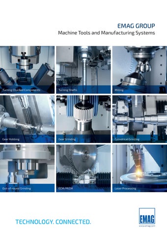
Turning Chucked Components
Turning Shafts
Milling
Gear Hobbing
Gear Grinding
Cylindrical Grinding
Out-of-round Grinding
ECM/PECM
Laser Processing
TECHNOLOGY. CONNECTED.
www.emag.com
EMAG GROUP At Home Around the World Based in the heart of Europe, EMAG has been a leading manufacturer of CNC machine tools since 1867. We offer processes for soft machining and hard machining – for metals and machinable materials. EMAG relies on proven machining processes such as turning, milling, and drilling – supplemented by a wide range of other machining technologies. The ideal manufacturing solution for virtually any application The EMAG Group is one of the few producers of manufacturing systems that covers the entire process chain, from soft to hard machining. With access to a very broad range of technologies (turning, drilling, milling, gear cutting, grinding, laser welding, ECM deburring, PECM machining, automation), EMAG implements complete process chains in producing transmission, engine, and chassis components, as well as in the non-automotive sector. In doing so, the long-established company from Salach, Germany draws on the comprehensive experience of all companies within the EMAG Group and offers its customers modular turnkey manufacturing solutions of the highest standard. As an OEM supplier, EMAG guarantees customers the fastest possible support. Upon request, we deliver a complete turnkey package: machine, tooling, workholding technology, cutting fluids, and a finished workpiece program. The customer receives a production-ready solution from a single source.
2,241 Total number of EMAG employees
8
Technology and manufacturing companies » EMAG Systems GmbH » EMAG Salach GmbH » EMAG KOEPFER GmbH » EMAG LaserTec GmbH » EMAG ECM GmbH » EMAG SU S.r.l. » EMAG Zerbst Maschinenfabrik GmbH » EMAG China Machinery Co., Ltd.
2
OUR LARGEST MARKET COMPANIES – GLOBAL SALES AND SERVICE:
EMAG Salach GmbH Spain Barcelona, responsible for the Spanish market EMAG Salach GmbH Salach, Germany, founded in 2014, responsible for the DACH markets as well as Central and Eastern Europe
21 14 Branches and
EMAG Salach GmbH France La Guerche, founded in 1981, is responsible for the French market
EMAG MILANO S.r.l. San Giuliano Milanese, founded in 2000, responsible for the Italian market
EMAG Middle East FZCO Dubai, United Arab Emirates, founded in 2024 EMAG L.L.C. Farmington Hills, USA, founded in 1995, responsible for the U.S. and Canadian markets
Maquinaria EMAG Mexico S de RL de CV
EMAG China Machinery Co., Ltd.
EMAG Korea Ltd.
Santa Rosa de Jáuregui, Querétaro, founded in 2003
Taicang, China, founded in 2004
Seoul, South Korea, founded in 2004
EMAG (Chongqing) Machinery Co., Ltd.
EMAG India Pvt. Ltd.
Chongqing, China, founded in 2016
Bengaluru, India, founded in 1998
EMAG do Brasil São Paulo, Brazil, founded in 1997
Global market companies (sales and service)
3
ALWAYS KEEPING THE BEST PRODUCTION SOLUTION IN How can quality and productivity in metalworking be significantly improved? This question is at the heart of what we do. That is why we develop manufacturing solutions that are specifically tailored to meet a wide range of requirements and deliver top performance—from cost-effective standard machines to complete manufacturing systems. In doing so, our engineers always keep the entire production process in mind. The focus is not just on the machine itself. The entire process – machining technology, NC programming, tools, automation, and energy consumption – is systematically optimized.
WE OFFER THE RIGHT MACHINE CONCEPT FOR EVERY APPLICATION: ✓
Tool and Mold Making + Universal cylindrical grinding machines
4
✓
Machining as a contract manufacturer + Machining centers with pick-and-place automation
MIND ADVANTAGES OF EMAG’S VERTICAL PICK-UP MACHINES In many applications, the vertical design and simple pick-up automation of EMAG lathes ensure significantly more efficient production. Compared to horizontal lathes, this means in most cases:
Significantly lower production costs – the following design features ensure this performance: + Compact design
Minimal space requirements thanks to a small footprint—ideal for modern production lines with limited space.
+ Integrated automation
Standard storage for raw and finished parts, as well as easy integration with robotic solutions, ensure maximum efficiency.
+ Maximum productivity
Automated loading and unloading via pick-up technology enables short cycle times and reduced non-productive time.
+ Cost-effectiveness even with small batch sizes Short setup times and simple operation ensure cost-effective production even with frequently changing components.
+ High machine stability
The vibration-damping polymer concrete machine bed ensures optimal process reliability and machining quality.
+ Excellent chip removal
Thanks to the vertical machine design, chips fall downward—for clean processes and infrequent cleaning intervals.
✓
Gear and Drive Technology + Machines for gear cutting and grinding
✓
Supplier to automotive, energy and other industries + Custom Machine Building: Complete production line for manufacturing brake discs, etc.
5
VL-MACHINES The VL Series vertical pick-up turning machines were specially developed for manufacturing precision chucked components. To cover as wide a range of parts as possible, the VL Series is available in four versions for a workpiece diameter ranging from 10 mm to 400 mm.
Machine body
X
Z-slide
Z
X-slide Spindle (Y)
Turret (optional Y-axis)
C
Measuring system (optional)
Automation
Intermediate gear
Sprocket
Machines: VL 2 Sawn part diameter: 60 mm Material: C45 2 OPs
Machines: VL 2 Pre-forged part diameter: 50 mm Material: 16MnCr5 2 OPs
Cover
Piston
Machines: VL 2 Sawn part diameter: 100 mm Material: X5CrNi1810 2 OPs
54,6 SEC. 100,8 SEC.
Machines: VL 4 Sawn part diameter: 100 mm Material: 46S20 2 OPs
35,4 SEC.
VL 2/VL 4/ VL 6/VL 8
143,4 SEC.
Workpieces
Main hub Machines: VL 4 Forged part diameter: 120 mm Material: 16MnCr5 2 OPs
100,2 SEC.
Drive gear Machines: VL 6 Forged part diameter: 220 mm Material: 16MnCr5 2 OPs
6
Housing Line cycle time
154,8 SEC.
212 SEC.
198,6 SEC.
Machines: VL 6 Sawn part diameter: 220 mm Material: 42CrMo4 3 OPs
Spur gear Machines: VL 8 External diameter: 320 mm Material: 16MnCr5 2 OPs
TECHNICAL DATA
VL 2/VL 100
VL 4/VL 200
VL 6/VL 300
VL 8/VL 400
Workpiece diameter, max.
mm
100
200
300
400
Chuck diameter
mm
160
260
400
500
Swing diameter
mm
210
280
420
520
Workpiece length, max.
mm
150
200
250
300
Travel distances, X/Y (optional)/Z
mm
650/± 50/375
760/± 60/415
900/± 30/495
1.010/± 30/595
inch
4
inch
6.5
inch
19.5
16.5
8
30/± 2.3/16.5
15.5
15.5
11
6
27.5/± 2/15
12
10
8
inch inch
8
20.5
10
35.5/± 1/19.5
12
39.8/± 1/23.5
» Power rating, 40%/100%
kW
Fanuc 15.7/13.9
» Torque, 40%/100%
Nm
77/59
74/55
256/202
243/183
491/340
462/340
826/600
776/600
rpm
6,000
6,000
4,500
4,500
3,100
3,100
2,850
2,850
Main spindle
» Speed, max. Turret » Turret tool positions
hp
ft-lb
21/19
57/44
Siemens 16.7/14.5
Fanuc 22.7/18
Siemens 24.1/18.1
Fanuc 41.1/28.5
Siemens 43/31.6
Fanuc 47.6/34.6
Siemens 48.8/37.7
22/19
55/41
30/24
188/149
32/24
179/135
55/38
362/251
58/42
341/251
64/46
572/443
65/51
572/443
Quantity
12
12
12
12
» Revolutions of driven tools
rpm
9,600
9,600
9,600
6,000
» Torque of driven tools at 30%/100% duty cycle
ft-lb
Nm
44/33
44/33
44/33
40/30
m/min
60/30/30
60/15/30
60/15/30
60/15/30
Rapid-traverse rate, X/Y/Z Control
ipm
32/24
32/24
32/24
30/22
2,363/1,181/1,181
2,363/591/1,181
2,363/591/1,181
2,363/591/1,181
Fanuc 32iB+/ Sinumerik ONE
Fanuc 32iB+/ Sinumerik ONE
Fanuc 32iB+/ Sinumerik ONE
Fanuc 32iB+/ Sinumerik ONE
7
VT-MACHINES Fast processes are required for machining large quantities of shafts. Both the machining process and the loading and unloading processes must be completed extremely quickly. The VT 2/VT 100 and VT 4/VT 200 machines are guaranteed to achieve the maximum performance you require. Four axes, short distances, and a powerful main spindle – these are the strengths of the VT Series. The full effect of these can be felt, in particular, when machining large quantities. A key factor is the machining of parts from two sides. This greatly reduces the machining time. Two tool turrets, each with eleven tool positions which can be equipped with turning tools or driven tools, ensure machine flexibility.
Turret 1 Working spindle with C-axis Turret 2
THE BENEFITS + Ready for integration with the
Tailstock
TrackMotion automation system
Automation
+ Reduced machining times due to four-axis machining
+ Shorter idle times with simultaneous
loading and unloading of components
+ Lower investment costs thanks to integrated automation
AUTOMATION SEQUENCE The gripper in turret 1 takes the workpiece from the raw parts storage area and transports it to the main spindle/tailstock. At the same time, the gripper in turret 2 takes the machined workpiece from the main spindle/tailstock, transports it to the finished parts storage area and deposits it there.
8
THREE KEY SUCCESS FACTORS + Reduced machining times
due to four-axis machining
+ Shorter idle times
with simultaneous loading and unloading of components
6
+ Highly productive shaft manufacturing thanks to integrated automation
SEC.
WORKPIECE CHANGEOVER TIME
TECHNICAL DATA
VT 2/ VT 100
VT 4/ VT 200
Chuck diameter
mm
160
250
Swing diameter
mm
210
270
Workpiece diameter, max.
mm
100
200
Workpiece length, max.
mm
400
630
Travel distances, X/Y (optional)/Z
mm 332/±25/625 395/±25/810
inch inch inch inch
6
8 4
15
10 10 8
25
inch
13/±1/24
15/±1/32
» Power rating, 40%/100%
kW
30.1/23.9
32.4/26.4
» Torque, 40%/100%
Nm
ft-lb
144/112
246/200
» Speed, max.
rpm
6,000
4,500
kW
33.5/26.5
33.9/29.3
Main spindle (Fanuc) hp
40/32
106/83
43/35
181/148
Main spindle (Siemens) » Power rating, 40%/100%
hp
VT 4
Workpiece diameter, max.: 100 mm
Workpiece diameter, max.: 200 mm
Workpiece length, max.: 400 mm
Workpiece length, max.: 630 mm
45/39
» Torque, 40%/100%
ft-lb
Nm
142/112
231/200
» Speed, max.
rpm
6,000
4,500
Rapid-traverse rate, X/Y/Z Revolutions of driven tools, max. Torque of driven tools, 30%/100% Control
105/83
2 x 11
Turret tool positions
VT 2
45/35
(2 x 1 gripper)
m/min
30/15/30
170/148
2 x 11
(2 x 1 gripper)
30/15/30
ipm
1,181/591/1,181
1,181/591/1,181
rpm
12,000
9,600
Nm
20/16.5
44/33.1
ft-lb
15/12
32/24
Fanuc 32iB/ Fanuc 32iB/ Sinumerik ONE Sinumerik ONE
9
VL MULTI-SPINDLE MACHINES – VL 3 DUO EMAG has extended the VL Series product range with the VL 3 DUO, a twin-spindle machine solution for the highly productive manufacturing of chucked parts up to 150 mm (6 inches) in diameter. The VL 3 DUO integrates all of the EMAG technological developments (including self-loading spindle, the TrackMotion automation system and the modular design of the machine) to create a highly productive manufacturing system with a minimum footprint. The latest generations of controllers from FANUC and Siemens enable easy operation of the machines.
HIGH-PERFORMANCE TURNING WITH THE VL 3 DUO The VL 3 DUO scores highly for heavy-duty machining due to its rigid machine design. High feed forces with a large cutting depth reduce the machining time. Standard spindle:
High torque spindle:
ap = 4.75 mm
ap = 8,5 mm
f =
0,4 mm/rev
f =
0,4 mm/rev
vc =
250 m/min
vc =
250 m/min
0.2 in
0.02 in/rev
1,000 in/min
0.3 in
0.02 in/rev
1,000 in/min
TECHNICAL DATA Workpiece diameter, max.
150
Swing diameter max.
mm
240
Chuck diameter max.
mm
210
Workpiece length, max./optional
mm
110/175
Travel distance, X/Y (optional)/Z
mm
505/±30/250
inch
6
inch
9
inch
8
inch inch
4/7
20/±1/10
» Power rating, 40%/100%
kW
Fanuc 17.9/15.5
» Torque, 40%/100%
Nm
ft-lb
144/98
» Speed, max.
rpm
5,000
5,000
» Power rating, 40%/100%
kW
Fanuc 31.5/28.1
Siemens 31.2/26.3
» Torque, 40%/100%
Nm
ft-lb
255/192
255/192
» Speed, max.
rpm
5,000
5,000
Main spindle (2x)
High-Torque-Spindel – Option
Turret (2x) » Turret tool positions » Speed driven tools
hp
hp
24/21
106/72
42/37.7
188/142
Siemens 20/17.2 145/112
26.8/23
107/83
41.8/35.3 188/142
» Torque driven tools
Qty rpm Nm
12 9,600 44/33
Rapid-traverse rate, X/Y/Z
m/min
60/30/30
Control
10
VL 3 DUO/VL 150 DUO mm
ft-lb ipm
32/24
2,362/1,181/1,181
Fanuc 31iB/Sinumerik ONE
VL 3 DUO FOR DEMANDING TURNING WORK + Working spindle with 5,000 rpm/32 kW/255 Nm at 40% duty cycle
+ Sturdy mechanical design – spindle flange to DIN 55026, size 6
+ Motor spindle with DirectDrive for minimum run-up
times, maximum true running and diameter tolerances
+ Maximum torque over large range of speeds MACHINING AREA OF THE VL 3 DUO:
+ Water-cooled motor spindle for maximum thermal stability
50
270
45
240
40 35
31,5
180
30
28,1
150
25
Torque (Nm)
6.000
3.600
Speed (rpm)
4.800
5 4.200
10
30 3.000
15
60
2.400
20
90
1.800
120
600
Torque (Nm)
192
Power (kW)
210
5.400
255
300
1.213 1.408
Highly productive machining of chucked parts with a diameter of up to 150 mm (6 inches) with minimum space requirements
Power (kW)
40 % ED
40 % ED
100 % ED
100 % ED
Maximum precision
Machine base made of MINERALIT® polymer concrete, machine weight 10,000 kg, roller guides and direct position measuring systems in all axes
Integrated automation
Pick-up working spindle for loading and unloading
Unique machine concept
Two working spindles and two high performance tool turrets with torque motor
Optimum accessibility
Short distance to the turrets and working spindle ensure optimum accessibility
Maximum flexibility
Parts storage area for up to 400 workpieces and TrackMotion automation system for high speed part transport between the parts storage area and machining areas as well as for turning the workpieces
Minimum floor space requirement
24.5 m2 for the complete machine: VL 3 DUO + TrackMotion + parts storage area + chip conveyor
* Fully equipped machine including chip conveyor, TrackMotion and parts storage area for up to 400 workpieces (depending on the workpiece geometry)
11
Classic MACHINES – UG SERIES The UG series is part of the EMAG Classic Line – the efficient entry into precision manufacturing. With grinding lengths ranging from 400 to 1,500 mm, the series covers a wide range of workpiece sizes – from short precision parts to long shafts and complex components with internal and external machining. Thanks to the combination of a robust base machine, high-quality EMAG components, and proven grinding technology, the UG series offers a technically sophisticated solution for workshops, toolmakers, and production companies that want to perform universal grinding tasks efficiently and reproducibly.
UG 1000
Grinding length: 1.000 mm
UG 400
Grinding length: 400 mm
UG 630
UG 1500
Grinding length: 630 mm
TECHNICAL DATA
Grinding length: 1.500 mm
UG 400
UG 630
UG 1000
UG 1500
Center height/Width between center
mm
175/400
175/630
175/1,000
175/1,500
Grinding length (straight wheel/angular wheel)
mm
400/240
630/450
1.000/825
1,500/1,220
kg
60
80
120
150
Weigth between center, max.
in in
7/16
16/9
7/25
25/18
7/39
39/32
59/48
lb
132
176
mm
100
90
90
3,5
-
Table stroke
mm
640
885
1,240
1,860
Min. increment / pulse
mm Nm
0.0001 8
0.0001 12
0.0001 12
0.0001 12
°
8.5
8.5
8.5
5
Slide stroke
mm
320
320
320
320
Travel min./pulse
mm
in
0.0001
0.0001
0.0001
0.0001
Min. increment / pulse
Nm
8
8
8
Clamping Ø (chuck) max.
in
4
3,5
264
7/59
331
Longitudinal axis (Z-axis)
Feed servomotor torque Machine table swivelling range Wheel slide (X-axis)
Machine table swivelling range Swivel axis (B axis) Swivel range B- Axis Resolution Swiveling time for 180° B- Axis Positioning Repeatability
12
in
ft-lbs
in
25
5.9
12.5
35
8.8
12.5
49
8.8
12.5
73
8.8
12.5
8
ft-lbs
5.9
5.9
5.9
5.9
°
8.5
8.5
8.5
-
° ° s
-15 bis +225 0.0001 8
-15 bis +225 0.0001 8
-15 bis +225 0.0001 8
-15 bis +225 0.0001 8
arc seconds
±2
±2
±2
±2
UG 400 Wheel Head (OD/face grinding) Grinding wheel (left/right) Ø
mm
in
500 × 40 (50ROS) × 203.2
UG 630 500 × 63 (80ROS) × 203.2
UG 1000 500 × 63 (80ROS) × 203.2
UG 1500 500 × 50 (80ROS) × 203.2
20 x 1.5 (50ROS) x 8
20 x 2.5 (80ROS) x 8
20 x 2.5 (80ROS) x 8
20 x 2 (80ROS) x 8
Spindle motor power Peripheral speed Internal grinding unit HF spindle mount Ø
kW m/s
7.5 60
7.5 (11 optional) 60
7.5 (11 optional) 40
7.5 (11 optional) 50
mm
120
120
120
-
Speed range Grinding wheel Ø
rpm mm
20,000–125,000 50
20,000–125,000 50
20,000–125,000 50
-
Workpiece spindle (workpiece head) Centering cone Spindle speed (stepless) Swivel range Motor torque
– rpm ° Nm
MT4 30–800 0 to +30 12
A2-4/MT4 (MT5) 30–800 0 to +30 22
A2-4/MT4 (MT5) 30–800 0 to +30 22
-
– mm
MT4 60/40
MT4 60/40
MT4 60/40
MT5 65/40
mm
±0.040
±0.040
±0.040
±0.040
Tailstock Centertaper Quill diameter/quill stroke Micro Taper Correction Dressing systems For external grinding/For internal grinding Hydraulic power unit Fuel tank capacity Engine power
in
in
ft-lbs
in
5
2
8,8
2/1.5
5
2
16
2/1.5
5
2
16
2/1.5
2.5/1.5
On workpiece head, dressing blades/on table swing arm type l kW
30 0.75
30 0.75
30 0.75
30 0.75
13
OTHER EMAG MACHINES Classic MACHINES An efficient introduction to precision manufacturing. Classic machines combine maximum efficiency with the high quality you expect from EMAG. These machines focus on the essentials and offer an optimized range of functions for typical machining requirements. The base machine is purchased from selected partners and equipped by EMAG with proven process and machining technology, such as chucks and tools. You benefit from EMAG‘s worldwide service network and fast spare parts supply – the ideal choice for cost-efficient production without compromising on reliability.
MSC 5 DUO
HSC 1
USC 850
The MSC 5 DUO is a twin-spindle CNC lathe engineered for highperformance batch production.
The HSC 1 is a compact, powerful CNC lathe for the economical machining of turned parts in two consecutive machining operations (OP 10 / OP 20).
The USC 850 is a state-of-the-art universal lathe that has been specially developed for the precision and efficient machining of large turned parts.
TECHNICAL DATA
MSC 5 DUO
HSC 1
USC 850
Workpiece diameter, max.
mm
120/240
375
700 (575)
Workpiece length, max.
mm
85/145
570
2,000
Swing diameter max.
mm
327
610
800
inch
inch
5/10
3/6
inch
13
OD CYLINDRICAL GRINDER WPG 7 – Compact, High-Precision Flexible OD Cylindrical Grinding Machine including Automation Thanks to its integrated linear gantry with a dual gripper, the machine handles the loading and unloading of workpieces autonomously and reliably, with extremely short chip-to-chip times. It is perfectly suited for short shafts up to 250 mm in length as well as for chucked components, and is ideal for flexible batch production with the shortest possible cycle times.
TECHNICAL DATA
14
Workpiece length, max.
mm
250
Center height
mm
100
Center length
mm
380
inch inch inch
10 4
15
15
22
24
27.5 (22.5) 79
31.5
GEAR-CUTTING MACHINES Gear technology for high-productivity gear manufacturing. Whether it’s state-of-the-art gear hobbing technology or the right machines for chamfering and deburring – EMAG has the right solutions for gears and worm gears. Many factors play a role in establishing an efficient production process. That is why EMAG develops highly creative, customized solutions based on its standardized gear cutting machines. The EMAG Group‘s range of gear cutting technologies:
+ Grinding Machines for Gear
+ Gear Hobbing Machines
+ Gear Shaving Machines
+ Skiving Machines
+ Gear Generating Grinding Machines
+ Gear Shaping Machines
+ Gear Profile Grinding Machines
Cutting Tools
+ Profile Milling Machines
TECHNICAL DATA
HLC 150 H Gear hobbing machine
CLC 200 HC Hobbing and Chamfering Machine
G 160 Gear generating grinding machine
GR/GW 250 Worm-type profile grinding machine
CLC 260 H FR Worm milling machine
Module range, max.
3
3 (5)
4
7
12
Workpiece diameter, max.
mm
150
250
160
250 (150)
260
Workpiece length, max.
mm
500
300
300
550 (500)
1,800/2,300
inch inch
6
20
10 12
6.5 12
10 (6)
21.5 (20)
10
71/90
15
EMAG LASERTEC
Systems for Laser Material Processing
Laser Welding
Laser Cleaning
Laser Hardening
Laser Cladding
EMAG’s laser systems set the standard for modern manufacturing processes. With innovative technologies, they sustainably improve the quality, efficiency, and productivity of your production. You benefit from significantly reduced lead times and perfectly coordinated process flows. Whether as a stand-alone solution or fully automated, EMAG laser systems enable the cost-effective production of highperformance, precision, and durable components – all with consistently high quality. This allows you to take your manufacturing to a new level and secure decisive competitive advantages.
TECHNICAL DATA Processes
ELC 6
ELC 6i
ELC 160
LSW, VW, F
LSW, LR, VW, F, DMC
LSW, LR, VW, F
Outer diameter, max.
mm
300
300
300
Workpiece height, max.
mm
300
300
300
TECHNICAL DATA
ELC 2500
ELC 1500 LMD
ELC 550
Processes
LSW, LMD
LMD
LMD
inch inch
12 12
12 12
12
Outer diameter, max.
mm
2,500 x 1,500
600
550
Workpiece height, max.
mm
600
1,500
250
inch inch
98 x 59 24
24
59
Process Legend: LSW = Laser Welding; LR = Laser Cleaning; LMD = Laser Metal Deposition; VW = Preheat; F = Joining, DMC = DMC Marking
16
12
22
10
EMAG ECM
Systems for Electrochemical Machining Electrochemical machining is based on the principle of electrolysis. The tool is connected as the cathode to a DC voltage source with the workpiece acting as the anode. A charge exchange takes place between the cathode and anode in an aqueous electrolyte solution, which targets specific areas of the workpiece. This can be used to create contours, ring ducts, grooves, or bell hollows with no contact but very high precision. The removed material is precipitated from the electrolyte solution in the form of metal hydroxide. The machining can be carried out regardless of the structural condition of the metal. Both soft and hard material can be machined. The components are not subjected to either thermal or mechanical stress.
TECHNICAL DATA
PTS
PI Premium Integrated
PS Premium Standard
PO 100 SF PO 900 BF
Generator capacity
A (DC)
2,500
400 – 2,500
400 – 2,500
2 x 2,500 – 5,000
Generator capacity
A (Puls)
6,000 – 12,000
400 – 8,000
400 – 8,000
2 x 6,000 – 12,000
Moving cathode
In the stationary cathode process, the workpiece is connected to the positive terminal, the anode. The tool serves as the stationary cathode. Both the cathode and the anode are connected to a power electronics unit. Depending on the application and quality requirements, the process can be operated using a constant DC current or a pulsed current. A continuously flowing electrolyte stream continuously flushes away the removed hydroxides. Typical applications include deburring or rounding off sharp edges on metal components.
In this process, the cathode – which is connected to the negative terminal and serves as the tool – is moved at a constant feed rate. The cathode has the negative contour of the geometry to be formed. The workpiece acts as the anode and is connected to the positive terminal. A constant electrolyte flow removes the hydroxides generated from the working gap. In most cases, the connected power electronics supply a pulsed DC current. This enables applications such as drilling and broaching.
UDC
Time t/s
Processing time per workpiece
UDC
Time t/s
Tool = Cathode
Electrolyte
Tool = Cathode
Precision Electrochemical Electrochemical machining (PECM) Precision electrochemical metal machining (PECM) takes this a step further. This process allows three-dimensional shapes to be machined from a workpiece. The basic setup is similar to the process described above, with the workpiece serving as the anode and the tool as the cathode. In addition, an oscillating motion of the tool is superimposed on the feed and pulse electronics. The working gap is significantly smaller than in the moving cathode process, which enables precision metalworking with tighter tolerances.
Processing time per workpiece
Tension U/V
Processing time per workpiece
Tension U/V
Tension U/V
Vertical cathode (ECM)
Oscillation stroke z/mm Tension U/V
UDC
Feed
Time t/s
Time t/s
Time t/s
Time t/s
Pulse train in the UT region
Tool = Cathode Electrolyte
Electrolyte
Workpiece = Anode
Workpiece = Anode
Workpiece = Anode
17
AUTOMATION SOLUTIONS FROM EMAG Automated production technology, precisely tailored to the requirements of components and material flow – with this goal in mind, EMAG develops a wide range of automation solutions. As a result, the entire production process becomes faster, less prone to errors, and more cost-effective. Our wide range of automation systems spans from gantry systems to our TrackMotion and robotic cells, all the way to our stacking cells in the SCS series. Thanks to this range of automation solutions, EMAG can implement a wide variety of manufacturing scenarios. Automation Systems: Integrated Material Flow for Increased Productivity
Image without safety fences
Do you want to compensate for labor shortages while simplifying processes and reducing unit production costs at the same time? Our automation solutions provide the ideal foundation for this. It is by no means necessary to commit to a large-scale system from day one. On the contrary: EMAG offers scalable automation solutions, such as EMAG’s own TrackMotion or our modular robot cell. Best of all, everything comes from a single source and is provided with precision, tailored to the customer’s requirements.
TRACKMOTION AUTOMATION SYSTEMS With TrackMotion, the TransLift moves along a rail system (“track”) through the automation aisle between the machines. The TransLift handles the tasks of picking up parts at various heights, as well as positioning and turning the workpiece. This makes it very easy to perform link-ups between machines, whether for parallel processing of identical operations or for sequencing successive operations.
+ Minimal setup time: The Track-
+ Integration of measuring
+ Space-saving, since the automation
+ Easy to maintain: The Track-
+ High reliability thanks to its simple
+ Short component transport
Motion automation system is ready for use once the workpiece height and part diameter have been entered. system is installed entirely behind the machines and sturdy design
18
devices, marking systems, cleaning machines, and many other functions is possible
The raw-parts are supplied via a parts magazine. This magazine has a storage capacity of up to 400 components, depending on the workpiece geometry.
Motion automation system is easily accessible from all sides. time: Travel speeds: 150 m/min horizontally and 35 m/min vertically
From small to large without retooling. The tool-free NC gripper ensures the fastest possible machine setup.
SCS STACKING CELL Highly productive production in a confined space – this is what is promised by the new stacking cells of the SCS series Whether for machining sleeve or shaft components, when combined with SCS stacking cells, EMAG machines become compact, fully automated manufacturing systems capable of operating autonomously for hours on end. While the SCS 1 is designed for smaller components fed on workpiece carriers, the SCS 4 can handle wire baskets up to 600 x 500 mm in size and weighing up to 40 kg. Part handling as well as machine loading and unloading are performed by a robot.
MRC ROBOT CELL: BIN PICKING Among other things, the modular automation solution enables the loading of machines with raw-parts directly from bulk material. EMAG’s vertical pick-up turning machines are highly automated in their own right; that is, both machining and unloading/loading via the pick-up spindle from the integrated workpiece conveyor are fully automated. The MRC is the perfect complement to this system, increasing autonomy and enabling the integration of secondary processes such as cleaning, measuring, or marking. If necessary, unsorted raw-parts can also be fed via a bin-picking module. A 3D camera system determines the positions of the raw-parts in the feed container. This data is used for the robot’s path planning, enabling it to pick the individual components one by one from the container (bin picking) and then place them on the machine’s workpiece conveyor.
CRC ROBOT CELLS Automation of Machine Tools with CRC robot cells – reliable, fast and efficient The CRC stacking cell is perfectly designed for handling smaller components. Loading occurs using workpiece carriers housed in drawers, each of which can hold up to 45 kg. An integrated robot handles the components as well as the loading and unloading of the machines. The machine operator is only responsible for replacing the workpiece carriers. If necessary, this can be done in parallel with the main machining time to ensure a continuous production flow.
19
www.emag.com
Display of the machines in their trade show configuration (with optional trim kit)
All EMAG Locations
359-1-GB/04.2026· Printed in Germany · © Copyright EMAG · Subject to technical changes.
At Home All Over The World.