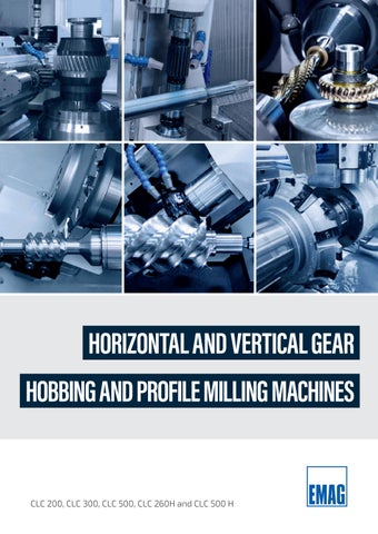
HORIZONTAL AND VERTICAL GEAR HOBBING AND PROFILE MILLING MACHINES
CLC 200, CLC 300, CLC 500, CLC 260H and CLC 500 H
CLC-Gear Hobbing Machines Highly Productive Gear Hobbing EMAG CLC gear hobbing machines were developed for highly productive manufacturing of precision gears, gear shafts, and worm gears, and have been renowned for their efficiency, quality, and versatility for many years. The machines are the result of years of research and development aimed at achieving high-quality gear hobbing results while increasing productivity.
KEY FEATURES OF EMAG CLC VERTICAL GEAR HOBBING MACHINES The CLC series consists of three vertical gear hobbing machines:
✓ CLC 200
✓ CLC 300
✓ CLC 500
» Workpieces up to 250 mm
» Workpieces up to 350 (400) mm
» Workpieces up to 500 mm
» Module 5
» Module 7 (10)
» Module 10
All machines have several features that make them ideal for a wide range of gear hobbing tasks. These range from straight and helical gears to worm gears, crown gears, and short teeth (splines) of various sizes. This makes the machines suitable for many applications and industries. The machines are equipped with a Fanuc CNC control as standard, with a Siemens control available as an alternative. 2
All machines can be equipped with the following technologies: gear hobbing, finish hobbing as a pre-toothing process, and skin hobbing as hard fine machining.
EMAG SU I CLC Series
SPECIAL FEATURES
+ The machines can be equipped for milling with oil and emulsion. In addition, the process can also be configured for dry operation, i.e., without coolant.
+ Longer hobs or multiple teeth with several tools can be clamped on the ground and hand-scraped tangential axis Y (shift axis). The milling head can be equipped with different speed ranges so that easily machinable material can be processed at high cutting speeds.
+ Tactile or inductive probes or
sensors can be used for workpiece inspection or position orientation and to check the gearing. There are various options for chip removal for magnetic or non-ferromagnetic workpieces.
3
CLC-Gear Hobbing Machines Stable Machine Construction and Direct Drives for Maxim The stable basic design of EMAG CLC gear hobbing machines has a positive effect on vibration behavior during milling. Like the milling head, the workpiece table is equipped with a direct drive. They also feature a hydraulic workpiece clamping device with the option of digital monitoring of the clamping path. This allows clamping operations to be performed on the workpiece table. In combination with the counterholder, gears and gear shafts can be clamped securely. A rough deburring device is also available as an option. This makes the machine ideal for the production of splined shafts, worm gears, crown gears, and gear wheels, making it a flexible solution for both series production and single-part production.
HIGHLIGHTS » Direct drives in milling head and tool table for maximum dynamics » Tangential axis with ground and hand-scraped guides for maximum precision and rigidity » Automatically movable counter bearing » High machine weight for vibration damping » Wide range of workpieces: gears, worm gears, crown gears, and splines
+
Y
AXLE ASSEMBLY
-
+
+ +
-
Z
+
X
A
-
CS1 -
+ -
WP
+
4
-
C Workpiece table
WE -
C
CS1 Tool spindle
+
-
+
-
A Swivel head
W
E
-
X
+
Radial travel
Z Axial travel Y Tangential travel W Tailstock travel Options: WP Hydraulic clamping WE Vertical travel E Axis of rotation Rimfire 2 or 4 stations
mum Precision + Maximum flexibility thanks to large working space
+ Tool spindle and work table with direct drive + High-speed gear hobbing spindle and work table
EMAG SU I CLC Series
ADVANTAGES AT A GLANCE:
+ The work table can be equipped with a
hydraulic workpiece clamping device with the option of digital monitoring of the clamping path
+ Also designed for dry machining + Tactile or inductive measuring probe or sensor for workpiece inspection
+ Magnetic chip conveyor + Tailstock movement via servo motors and preloaded recirculating ball screw
+ Hobbing mandrel with ISO and/or HSK80 cones + Robotic loading onto the spindle with automatic door
+ Chamfer cut on the main spindle + L-shaped door for loading with a crane Optional:
» Long tangential axis Y (for longer gear hobs or multiple tools)
» Scraper chip conveyor for non-ferromagnetic materials (steel, aluminum, or bronze)
» 2-NC ring loader for minimal setup effort » Coarse deburring station under the workpiece
TECHNICAL DATA Workpiece diameter max.
mm inch
Module
CLC 200
CLC 300
CLC 500
220
350
500
5
7 (5)
10 (6)
9
14
20
Workpiece length
mm
600
600
850
Axial travel (Z)
mm
370
400
600
Tangential travel distance (Y)
mm
200
250
300
1/min
1.300 (2.500)
1.300 (2.500)
700/1200
mm
140 x 210
160 x 255
160 x 300
ISO 40
ISO 40
ISO 40 (HSK80)
12.000
16.000
18.000
Milling spindle speed Drill diameter X Length max.
inch inch inch
inch
Tool clamping Machine weight
kg
24
14 8
5x8
24
16
10
6 x 10
33
24 12
6 x12
5
CLC 260 H (HW) – CLC 500 H Horizontal Gear Hobbing Machines The CLC 260 H (HW) and CLC 500 H horizontal gear hobbing machines can be used to machine gears, worm gears, and long toothed shafts with maximum precision. Their quick changeover to new workpieces makes them ideal for producing individual parts and series. In addition, the machines can be equipped with automation systems, increasing their versatility and efficiency. CLC machines are available with different axial travel distances, which makes them particularly interesting for machining shafts with multiple teeth.
TECHNICAL DATA
CLC 260 H
CLC 260 HW
CLC 500 H
260
260
500
6
10
22
mm
Workpiece diameter max.
inch
10
Module max.
10
20
Axial travel max.
mm
1.500 (2.000)
1.500
2.000 (3.000)
Disc cutter diameter/width
mm
160/50
240/100
350/400
Hobbing cutter (diameter/length)
mm
160/255
180/255
350/400
Milling spindle speed
1/min
1.300 (2.500)
1.300
600
Table speed
1/min
250
250
68
kg
16.000
19.000
35.000
inch
59 (79)
inch
6/2
inch
Machine weight
6/10
59
79 (118)
9/4
14/16
7/10
14/16
+
+
C
Y -
-
WL
+
+
-
+
A
CS1 +
A Swivel head
X
CS1 Tool spindle
-
AXLE ASSEMBLY
W +
C Workpiece table X
Radial travel
Z Axial travel Y Tangential travel
-
6
Z
W Tailstock travel
+
WL Bezel (CLC 260 H only)* *manual or automated available as an option
+ Highly flexible gear hobbing machine for gears, worm gears, and long toothed shafts
+ Minimal setup effort when clamping between face driver and tip
+ Automatic or manual steady rests + Separate NC slide for moving the steady rest along the workpiece
+ Additional NC-controlled air
EMAG SU I CLC 260 H – CLC 500 H
ADVANTAGES
nozzles for oil blowing
+ Table through-hole for long, thin shafts
+ Multiple gear teeth on one shaft Highlights:
» Machines available with different axial travel
» Direct drive in table and milling head » Milling head with ground and handscraped tangential axis
» Automatic counter bearing in milling head » Automation with robot or gantry loader » Table through-hole » NC axis for mounting a steady rest
HORIZONTAL GEAR HOBBING MACHINES The CLC 260 H (HW) and CLC 500 H (FR) are suitable for machining medium and large rotors and rotary pistons. Rotors can be manufactured using the gear hobbing process or the single-part process.
✓ CLC 260 H
✓ CLC 260 HW
✓ CLC 500 H
» Workpieces up to260 mm
» Workpieces up to260 mm
» Workpieces up to500 mm
» Module 6
» Module 10
» Module 22
7
CLC 260 H FR – CLC 300 FR Profile Milling Machines for Processing Worms When it comes to machining worms for worm gears, the CLC 260 HR (horizontal profile milling machine) and CLC 300 FR (vertical profile milling machine) are used. On these machines, the workpiece is machined with a profile cutter.
The Machine Types – Machining of Worms:
HORIZONTAL PROFILE MILLING MACHINE
VERTICAL PROFILE MILLING MACHINE
The horizontal profile milling machine is particularly suitable for milling worms or hydraulic spindle pumps. The machine is automated using a robot or a gantry loader.
The vertical CLC 300 FR is equipped with a profile milling head and can load workpieces with a ring loader. In addition, additional operations, such as keyway milling, can be integrated in the 90° position of the ring loader.
✓ CLC 260 H FR
✓ CLC 300 FR
» Workpieces up to 260 mm
» Workpieces up to 200 mm
» Module 12 (28 mm cutting depth)
» Module 10 (22 mm cutting depth)
The Machine Structure These machines are designed for efficiency and precision. They feature powerful milling heads and tool tables and are designed for heavy-duty machining with high torques on the milling spindle. Another special feature of these machines is that steady rests can also be added to support the workpieces.
CLC 260H FR -
C
AXLE ASSEMBLY
A
CS1 -
+ +
-
+
X +
A Swivel head
-
CS1 Tool spindle
W
C Workpiece table
+
X
Radial travel
Z Axial travel W Tailstock travel
-
8
Z
WL Bezel*
+
*manual or automated available as an option
The milling head of the CLC 260 H FR and CLC 300 FR is made of cast iron for better vibration damping and can accommodate solid carbide disc cutters or carbide indexable insert cutters. The milling head is designed for high torque on the milling spindle and is equipped with an HSK interface for quick tool change.
EMAG SU I CLC 260 H FR – CLC 500 H FR
HIGH-PRECISION PROFILE MILLING
Optionally, the milling head can be equipped with a counter bearing. For more demanding tasks, such as profile milling of rotors, rotary pistons, or large screws, there is a reinforced version, the CLC 260 HW or CLC 5000 H FR, with a stiffer machine bed and greater milling capacity. (See Rotor Milling).
TECHNICAL DATA Workpiece diameter max. Milling depth Ttravel distance Z Milling diameter
CLC 260 H FR
CLC 300 FR
mm
260
200
mm
28
22
mm
1.500/2.000
400
mm
200–250
200–250
HSK 80A
HSK 80A
inch inch inch inch
Tool clamping
10 1
59/79 8–10
8 1
16
8–10
Swiveling tool head
°
± 60
± 45
Machine weight
kg
16.000
16.000
9
CLC 260 HW – CLC 500 H FR Rotors, Rotary Cobs and Large Screws Machining The Machine Types – Profile Milling of Rotors and Rotary Pistons:
HORIZONTAL PROFILE GRINDING MACHINES The machine is the heavy-duty version of the CLC 260 H FR with ground and hand-scraped guides in the tangential, radial, and axial directions. Gear hobbing with gear hobbing cutters and profile milling with single-piece milling cutters can be used here as a process for rotors.
✓ CLC 260 HW » For rotors up to max. 160 mm » Rolling and profile milling » Max. profile height 42 mm
CLC 260 HW for machining rotors
This machine has a profile milling head and can machine large profile depths with a single-piece milling cutter. This machine has ground and hand-scraped guides in the radial and axial directions.
✓ CLC 500 H FR » For rotors up to max. 500 mm » Profile milling » Max. profile height 80 mm
CLC 500 H FR for machining rotors
TECHNICAL DATA Workpiece diameter max. Milling depth Workpiece length Milling cutter diameter / Disc width Milling diameter / Cutter width Maximum workpiece weight Axis
10
CLC 260 HW
CLC 500 H FR
mm
260
500
mm
42
80
mm
1.500
2.000 (3.000)
mm
240/100
350/450
mm
180/255 7/10
-
Kg
500
1.500
Piece
5
4
inch inch inch inch inch
10 1
59
9/4
20 3
79 (118) 14/18
EMAG SU I CLC 260 H FR – CLC 500 H FR
THE CLC 500 H FR: A HEAVYWEIGHT IN ROTOR PROCESSING The CLC 500 H FR is the perfect machine for heavy-duty clamping. Its design with flat guides, which provide additional rigidity, makes it ideal for meeting demanding machining requirements. Powerful Processing Parameters The CLC 500 H FR can perform machining of a profile height of 80 mm in a single cut. The direct-drive table is designed for high chip capacity and has very high torque.
11
Automation Solutions Automatic Loading A ring loader with two stations is available for the vertical gear hobbing machines. The ring loader offers many advantages: for example, two NC axes (E and WE axes) allow the workpiece to be loaded and unloaded directly into the clamping device. But it also makes setting up the machine much easier: the two NC axes can be used to move to different positions, meaning that only a minimum of replacement parts are required when retooling for a new workpiece. This simplifies handling and enables flexible automated production. Another advantage is that the coarse deburring disc can be hydraulically adjusted axially and radially to the underside of the workpiece (optional). This greatly reduces the manual changeover effort, increasing the versatility of the machine, making it well-suited for small series production. In summary, the ring loader offers an efficient, versatile, and cost-effective solution for a wide range of applications. With its short setup times, minimal number of replacement parts, and the adaptability of the deburring disc, it offers significant advantages for any production process.
Conveyor belt with workpiece pick-up via a ring loader.
12
Robot loading from the rear with loading door.
Stacker cell with surrounding conveyor belt.
+ Flexible automation for flat and shaft-type workpieces
+ For shaft machines Flexible automation for shafts of different lengths and diameters
+ Low setup effort + Blowing off components in the machine
EMAG SU I Automation Solutions
ROBOT AUTOMATION
+ Additional operations possible
PORTAL AUTOMATION + High-capacity stack magazine + Additional operations possible + Blowing off components in the machine
13
TECHNOLOGY. CONNECTED. Turning Chucked Components
Gear Grinding
Turning Shafts
Cylindrical Grinding
Out-of-round Gr
Milling
rinding
Gear Hobbing
ECM/PECM
Laser Processing
Machines shown with optional decorative sheet kit. 338-1-GB/06.2026 · Printed in Germany · © Copyright EMAG · Subject to technical changes.
At Home All Over The World.
All EMAG Locations
www.emag.com