
2 minute read
1) STRUCTURAL COMPOSITION


1.1) REFERENCES FOR STRUCTURES
The structure settings of our building are a complex system that took reference from existing technologies to achieve static goals by simple, yet high-performing solutions. The outer rings of our layout are assembled with the same geometrical layout of typical alpine architecture, which uses a yuxtapsition of beams to end up distributing the snow heavy loads evenly through the element’s structural jerarchy. In this way, we used steel beams with the same philosophy of the wooden composition of this “chalets“, achieving high staticity, performance and lightness. The wooden planks that terminate the roof, in our case, are substituted by a technological compound called sandwich pannel, which uses two- sided steel laminates to cover a thick layer of rigid insulation. In this way we can, together with a density of tertiary beams , apply both rigidity to our roof and high-performing insulation coincidently. The arena, in the other hand, uses a complex steel roof that assembles a light upper series of beams with highly tensile resistant pre-tensioned cables lower body. This connection is made possible by connecting steel column thrusses entitled exclusively to bear compression. In order to understand this system, it was necessary to understand various similar systems, such as the Madison Square Garden and the wheel of a bike.
Advertisement

1.2) VERTICAL ELEMENTS
The structural grid is composed in all intersections by vertical elemtents is reinforced concrete. There is precense of stiffening elements along the grid such as bearing walls and distribution cores in strategic areas. These elements are jerarchically dimensioned and serve the sole purpose of transfer the loads from the horizontal structures All vertical elemnts are perpendicular to the ground as shown in the plans.
1.2.1) COLUMNS
The columns of our project are of two different diameters: 600mm and 800mm, and made of reinforced concrete.. The thickest one is to support the tensile structure roof and part of the translucent roof over the perimetral gallery ring, tgether with the two floors of the arena, where the entrances to the seating sections and the VIP section are.
The Selected one of 600mm is used on all spaces outside of the arena’s perimeter to be loaded by one floor and the outer opaque roof.
1.3) HORIZONTAL ELEMENTS
The horizontal and low-pitch inclinated rof elements are sustained mainly by bending (beams). In the case of the floors, a steel deck that combines corrugated steel with reinforced concrete is layed on top of beams spanning around 2m, letting a better load distribution. These beams, primary and secondary over all floors above the 0 level. These will be under the dead loads of a steel deck, nonstructural elements and live loads. As for roof beams The same principle is followed, although, it differs by an addition of terciary beams to turn by 90 degrees the lad flws on the composite pannel. This pannel is composed by an insulated inlay covered by steel sheet, making it structural.


1.4) TENSION ROOF
The design of the tension roof is a complex set up of intersected beams bounded by an eliptical shape, from which is present a higly resistant compression beam to prevent as much as possible horizontal deformations.
These points of intersection will be a node composed by the hinge of the upper compression beams, the cable under tension loads of the structure plus pretension forces applied to diminish vertical deformation, and the pillars to sustain in height the whole system.
Compression arches in catenary tridimensional elipsoidal composition composition
Moment connection: All DOF fixed
Compression struts
Hinge connection: Rotation DOF Released
Pre-tensioned cables
HInge connection: Rotation DOF Released
Round cross section pre-cast R.C. pillars
Very first sketch of tension roof design.
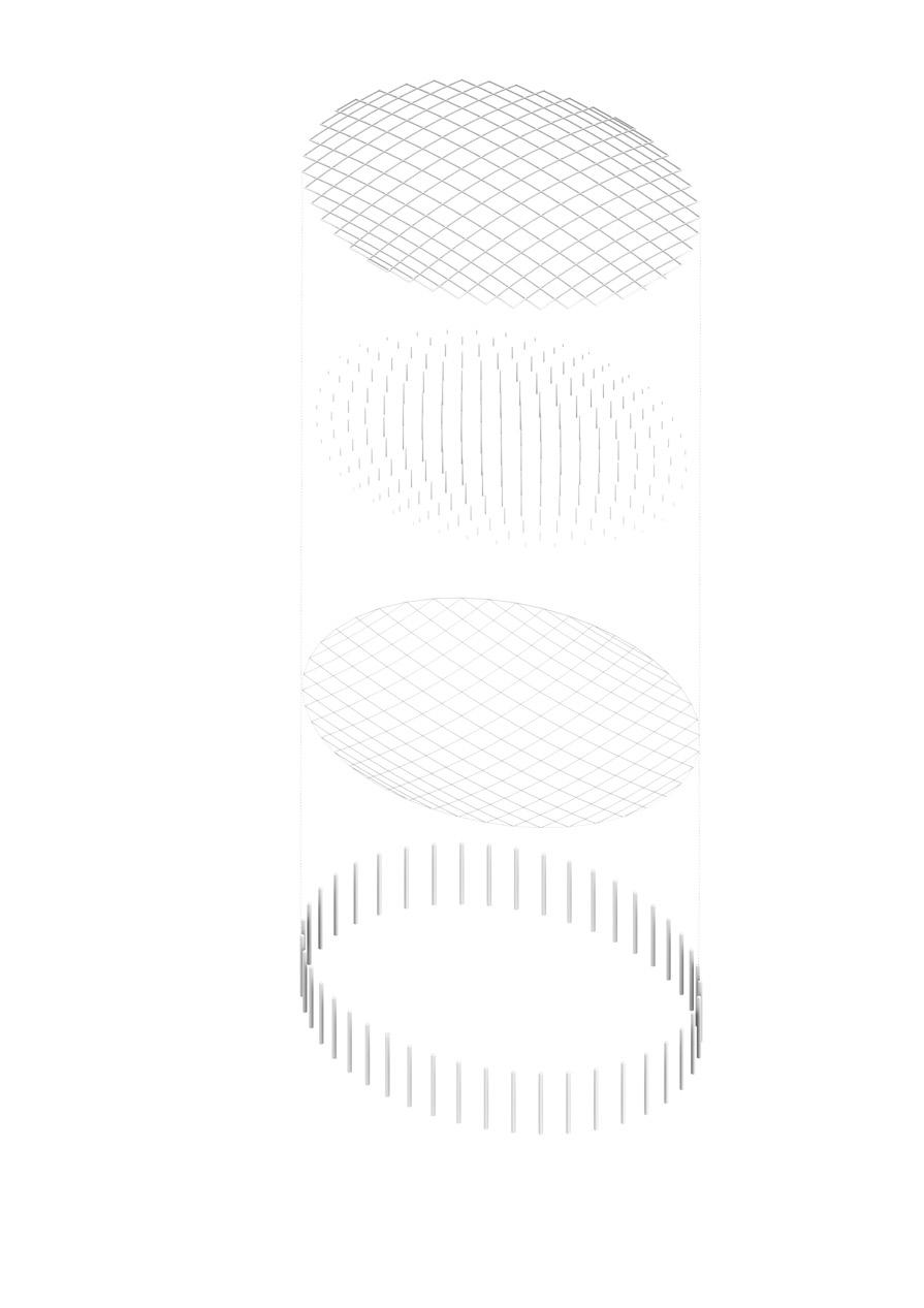
GRASSHOPPER STEP-BY-STEP ROOF CODING: 1-4
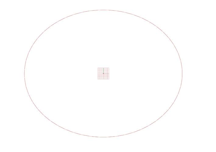
1.4.1) TENSION ROOF GEMETRY GENERATION

GRASSHOPPER STEP-BY-STEP ROOF CODING: 1-4
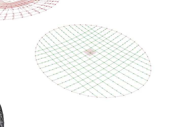
Selection of nodes for connecting beams
LOD 300
Orthogonal composition of primary structure


LOD 300
STEP-BY-STEP ROOF CODING: 6-10
GRASSHOPPER STEP-BY-STEP ROOF CODING: 6-10
STEP-BY-STEP ROOF CODING: 6-10
GRASSHOPPER STEP-BY-STEP ROOF CODING: 6-10


LOD 300
LOD 300


