
10 minute read
DESIGN TIPS TO SHEET METAL PARTS CONCEPT, AND BIW STRUCTURES MANUFACTURING.


Advertisement
Paper by Daniel Perez
Hello everyone! Here we go - again - with another publication exploring some real examples and tips around BIW Structures designing and manufacturing. But before, I would to start with a general hint to everyone working in engineering or manufacturing; no matter your experience, the product you are developing, the company you are working for or the planet you are living in:
NEVER DESPISE OR CRITICIZE A DESIGN CONCEPT YOU WERE NOT FULLY INVOLVED IN DURING THE ENGINEERING AND MANUFACTURING DEVELOPMENT PHASES, EVER!
In general, I believe this is a normal “engineer mindset”: I could have designed this product more efficiently, or, if this part has been designed differently it would be way better, kind of: I have the “Eye of Thundera” and can see beyond reach - ThunderCats roar!!! That’s fine. Conflicting and questioning the existing environments is how we change and grow our business, and this is also part of the engineer mindset - we’re taught to question everything.
But, there is an important point you can never forget whilst engineering, manufacturing and mainly launching a new product - TIME. The clock never stops, and there is an enormous chain behind the launch phases that can’t be easily changed, or better saying, yes it can be changed, but will often affect the business plan negatively. So, that’s why no matter the road-blocks faced during launch phases, it has to overcome them and keep moving, always focusing on quality and obviously, on timing.
Back to the initial point, I learned it in the best way everyone can learn something new, on the field. To be honest, I believe I will never forget that weird body bracket I had to design and release ASAP during a launch phase years ago. Another thing I’m pretty sure is that everyone who seen that bracket will first think: Who made this? I confess, I felt like it was doing my job wrongly or badly done.
The point is, considering the timing, issue severity, package constraints, system interfaces, vehicle attributes, manufacturing restrictions, stamping feasibility, etc., that was the best we could do at that time, and I can tell you, the team worked very hard. Yes, the best design to solve the issue was released - the target - and believe me, there were dozens of experienced engineers working together for days until they found the best solution, on time.
The root cause was a NVH (Noise, Vibration, and Harshness) issue discovered after a driving test, and if you - ThunderCats engineer - already had the chance to work on the field solving a NVH issue, guess I don’t need to say anything else more. If you don’t, please get back to the first quote of this text.
So, how can anyone just say that design wasn’t the best without knowing all the facts during that time it was released?
No way!!
Thus, no matter the design architecture or product you’re seeing, or whatever you think it could be done better, always keep in mind that “behind the scene” there are plenty of constraints and deliverables driving the design and manufacturing definitions, which sometimes simply cannot be delivered differently, period.
Yes, things can often be changed, design optimized and manufacturing process improved, but the timing plan often decides by when and how.
In the end, the main target will always be quality, aimed to ensure customer’s integrity and overcoming their expectations, on time! Keep questioning, but never criticizing.
STAMPING MARKS, A USEFUL FEATURE TO HELP THE MANUFACTURING TEAMS PLACE THE PUZZLE PIECES IN THE RIGHT PLACE.
I believe it’s clear to everyone that using manual operations in some production steps is not so efficient due to many reasons, being quality, timing and labor costs often the main concerns, but oftentimes there is no other option than to go for manual process.
So, to make the process repeatable enough and these steps easier for the operators to ensure the right quality, basically two solutions are used:
- Masks, jigs, or templates. Usually added at final assembly lines, are additional jigs designed to drive the installation of some parts into the vehicle structures and ensure the correct application. For this solution, there are additional costs related to the jigs.
- Stamping marks. Basically, these are permanent marks added into sheet metal parts during the stamping process to drive the correct installation of some system interfaces, a good practical example - still in body shop - is the installation of structural adhesives. Well, adding a structural adhesive in the wrong position doesn’t help, right? Sure it doesn’t. So, defining the right positioning where the structural adhesives must be placed is how potential issues are mitigated, and this same strategy is also used to apply some labels at final assembly.
In fact, the stamping marks have many applications and useful functions during the manufacturing process in all shops, which means every time some part needs to be manually installed, clipped or glued in the body structures or some process locked directly to part’s design, it’s highly recommended to provide permanent marks.
Another good example of stamping marks supporting product functionality is the Child Lock, those little marks you can see close the door latches to advise whether the door is locked/ unlocked and avoid any child taking off the car, accidentally. Looks simple, but this feature delivered by stamping marks is so important, even most of the kids often hate this.
So, anytime you need to ensure the quality of some process or system function, bear in mind that using the stamping marks is a cheap, simple and very useful strategy.
Ah!! Don’t forget to check the stamping process!!
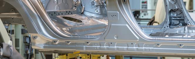
CLEARANCE HOLES, LOOKS SIMPLE BUT A WAY MORE COMPLEX DESIGN DELIVERABLE THAT NEEDS HIGHLY ATTENTION.
It’s quite normal having some bolted and clipping interfaces in the BIW structures, remember that besides passenger integrity the body structure is a donor system, which means designed to support all interfaces, or to simply hang all other parts and systems, similar to a human body skeleton.
But the point is, not always the fixing points can be delivered in the first surface layer, which means the parts carrying the weld nuts and clipping points might be overlaid by other part surfaces and that’s why need HIGHLY attention to consider clearance holes around the joints and avoid shadowing condition - blocking points.
Important point-out that some predefined clearances and hole sizes are considered based on material stack-up and type of joint, but it is quite important to always consider the assembly variation around the joints to define the proper clearance, including overall manufacturing process - the real world.
Holes shadowing is the last thing you want to face during manufacturing roll-out phases, and if you didn’t predict it since the initial design phases based on design variation analysis (DVA), you’re done. Well, just think about it, if you didn’t predict the clearance hole correctly in advance, it means that you may need to change the stamping tooling adding unexpected cost and affecting the timeline.
This design strategy is applied not only for bolted and clipping joints, but also for locator holes overlaid by other parts, and this is even more critical. Well, without locator pins access, you can not load the parts into welding jigs correctly to proceed with the proper assembly marriage process - line stop.
So, here is a tip for you. Every time you’re designing some sheet metal part or BIW system, always try to look from a manufacturing point of view, and bear in mind that all the beautiful data you have made on your computer screen often is not as beautiful as you expect on the shop floor.
Care about the journey the design will get from product engineering to all manufacturing sites is also part of product engineer work.
TOY TABS – A HELPFUL AND SIMPLE DESIGN FEATURE TO SUPPORT THE MANUFACTURING PROCESS DURING BIW FRAMING STEPS.
Depending on the manufacturing flow chart, lines preset and considering the full body side framing process, it is not always possible to load the body side frames and apply the first geo-joints on the same station. So, first the body sides need to be loaded and pre-assembled into the underbody structures, then moved to the next station to start the welding operations.
The point is, this operation needs to be safely carried to ensure the sub-assemblies won’t fall down during moving to the next station and that’s why the toy tabs are used for, to simply hold the system marriage until the first spot welds are applied.
Toy-Tabs features are basically little tabs added into specific areas - that can be in upperbody or underbody structure - to hold the systems` marriage before starting the upcoming welding operations. Basically, the tabs are bent down after marriage and used as clamping to hold the system’s marriage until the next station. The bending operations are often made by robots, but sometimes also manually, depending on the station and system.
For body side framing, it’s normally added about 4 to 6 tabs each side in some specific areas like hinge pillar, A pillar, rocker, rear quarter and wheelhouse, but the design architecture and body process that drive the application of this feature.
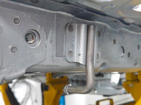
Important to point out that the toy-tabs don’t hold the systems into final geometric coordinates, so before starting the upcoming welding process the systems are located properly using the master locators.
Sometimes, this strategy is also used in roof-bows, front and rear headers and roof cross members’ assembly process.
In other hands, anytime the loading and welding can not be made on the same station but need to safely carry the body into the next station, the tabs are added to support the next assembly steps.
SQUARE TO GRID LOCATING STRATEGY, A MUST HAVE DESIGN REQUIREMENT TO SUPPORT MANUFACTURING PROCESS.
Every single sheet metal part has its own locating strategy - this is a must have - the same for all next sub-assemblies layers. But, all sheetmetal parts and assemblies often have something in common, the master orientation.

The complete BIW assembly has a master hard point (X,Y,Z) based on vehicle coordinates, the same for all the other systems and interfaces. This is to properly manage all geometric variations and drive the upcoming process and assembly steps. In the end, all parts and systems refer to the same hard point to being manufactured, measured, assembled into a vehicle and monitored.
Based on that, the sheet metal parts locating follow this same strategy. All locator holes refer to master orientation position, which means the surfaces of locator holes are parallel and pierced in perpendicular orientation to master vehicle coordinates depending on loading direction, this is often called “square to grid strategy”, and it’s also part of GD&T work stream.
I confess you, sometimes this strategy it’s a big constraint for the design architecture and stamping process, once demands additional features into parts such as pockets and embossments to deliver the master orientation, besides affecting part balance in die set tools, but it’s quite helpful for manufacturing process control.
Remember all those process variations during assembly steps? Well, can you imagine having dozens of references and orientations to handle and drive the tuning into welding fixtures, die sets and design? That’s the point.
Using square to grid strategy the variations of inputs are reduced, besides simplifying the parts loading into welding fixtures during assembly steps by defining a common path, the traveling always ends square in line to master vehicle coordinates.
This is a simple design strategy and I can tell you, having all parts using the same geometric orientation during all manufacturing steps is quite helpful to drive assembly line adjustment besides quality issues resolutions.
LAST, BUT NOT LEAST, I WOULD LIKE TO TIE UP THIS ARTICLE WITH A SIMPLE QUESTION:
WHY IS IT SO IMPORTANT HAVING THE MANUFACTURING TEAMS ONBOARDING SINCE THE INITIAL PRODUCT DEVELOPMENT PHASES?
Well, the PRODUCT engineering work ends up only at the shop floor with products “in hands”, right? Right! So, how can somenone design the body architecture, select the raw material and gauges, define the joints, system interfaces and, mainly, ensure the vehicle attributes achievements without considering the entire manufacturing process? Whether you’re working as a product engineer or designer and still thinking your work it’s finished by releasing cool CAD data, better you change your mind.
So, here is JUST a simple example why product and manufacturing engineering teams need to ground together to ensure the PRODUCT will deliver the right quality in the end-of-line.
During the main manufacturing steps, the BIW needs to be geometrically referred and carried by some points, we often call them hard-points, and these points are used since the initial platform and framing assembly steps in body shop during welding marriage, moving to paint shop including static sealing and coating applications and then to final assembly lines (general assembly), before wheels down.
Besides process, the BIW structures needs to be stable enough during the manufacturing steps to avoid dimensional side effects, which means these points even that designed for process purpose are also part of product deliverable, including some vehicle attribute targets such as: torsional, stiffness, water tightness and corrosion protection.
The point is, no never the same points can be used in all the process, which means more than one hard-points strategy is often required across the shops during the manufacturing steps, including locator holes and rest surfaces. The main reason is because the BIW needs to be handled-over from one to another shop, also inside the same shop from one to another process, for example from skids to geo-pallets, from geo-pallets to overhead conveyor.
Interesting point out that the BIW center of gravity is an important input considered whilst defining these points. Well, the BIW needs to be safely carried - safety first!
But, the main target always must be the VoW (vehicle on wheels), which means whatever the hard points needed to support the manufacturing process, they need to be managed afterwards to deliver the right vehicle attribute targets - PRODUCT.
Thus, bear in mind that depending on your design strategy, during and/or after the manufacturing process, holes need to be plugged (water tightness), rest surfaces must be properly covered (corrosion protection) and all of these deliverables are also part of product development.
Whatever the name you call it, no matter your role around the development process, product and manufacturing engineering always need cross-functionally work together to ensure the complete vehicle will deliver the correct and expected quality, including functional targets. Period.


