SDR with HackRF One & HackRF Pro
Programming with GNU Radio
●
Burkhard Kainka
●
© Copyright 2026 Elektor International Media
1st edition 2026
All rights reserved.
The contributions published in this book, in particular all essays and articles, as well as all designs, plans, drawings, and illustrations, are protected by copyright. Their reproduction and distribution, even in part, is generally only permitted with the prior written consent of the publisher.
The information in this book is published without regard to any potential patent protection. Software and hardware designations mentioned in this book may be registered trademarks, even if not specifically indicated. They belong to their respective trademark holders and are subject to legal regulations.
The greatest care has been taken in compiling the texts and illustrations. Nevertheless, errors cannot be completely ruled out. The publisher, editors, and author cannot assume any legal responsibility or liability whatsoever for incorrect information and its consequences. The publisher and author are grateful for notification of any errors.
The author, translator, and publisher have made every effort to ensure the accuracy of the information contained in this book. They accept no liability for any loss or damage caused by errors or omissions in this book, regardless of whether such errors or omissions are due to negligence, oversight, or any other cause, and hereby disclaim all liability to third parties.
● Cover design: Elektor, Aachen
Editor: Elektor Media Team
Printers: Ipskamp, Enschede, The Netherlands
● ISBN 978-3-89576-749-4 Print 978-3-89576-751-7 eBook 978-3-89576-752-4 ePub
● www.elektor.com
Elektor is the world's leading source of essential technical information and electronics products for pro engineers, electronics designers, and the companies seeking to engage them. Each day, our international team develops and delivers high-quality content - via a variety of media channels (including magazines, video, digital media, and social media) in several languages - relating to electronics design and DIY electronics. www.elektormagazine.com
7.4
7.5 Filter Parameters
7.6 Signal propagation times
Chapter 8 • HackRF FM Receiver
Tunable FM
8.3 Adjustable Signal Gain
8.4 Computer Load
Chapter 9 • Shortwave Receivers
9.1 Shortwave AM Receiver
9.2 Simple SSB Reception
9.3 SSB Filter
Chapter 10 • GNU Radio Transmitter
10.2 AM Test Transmitter
10.3 FM Test Transmitter
Chapter 11 • Amateur Radio Applications
11.1 Isolation
11.2 A 20-m SSB Generator
11.4 An RF power amplifier
11.5 Two-tone Test
11.6 Narrowband FM on 2 m
Foreword
HackRF is an open-source development by Great Scott Gadgets and serves as a front end for software-defined radios (SDR). It allows anyone to develop their own SDR software, build specialized receivers and transmitters, or solve complex tasks in RF measurement technology.
HackRF One has been on the market for a long time and has already been used for a wide variety of tasks. Its improved successor, HackRF Pro, is now available. Both share an enormous frequency range extending beyond 6 GHz, as well as extensive configuration options for reception and transmission.
This book aims to make it easier to get started with SDR technology using the HackRF. Its main focus is an introduction to GNU Radio as the most important tool for programming SDR applications. Whether it involves building receivers, simple transmitters, or specialized applications in amateur radio, manageable solutions are presented for each of these areas.
Digital signal processing is not a simple subject. At first glance, it seems like something for true specialists. But the available tools are so good that even beginners can gradually find their way into the subject. Often, functional blocks are used as black boxes before they are fully understood. But through hands-on experiments, it becomes clearer exactly what is happening there. Working with the HackRF leads to an ever-improving understanding of the details of digital signal processing.
Good luck with the HackRF!
Yours, Burkhard Kainka, DK7JD
www.elektronik-labor.de
Chapter 1 • Introduction
If you’re holding a HackRF One or HackRF Pro for the first time, you’ll probably want to get your device up and running as quickly as possible and start your first test. In reality, however, there’s so much information available that it’s easy to get overwhelmed. That’s why we’re starting with a quick guide featuring the most important tips.
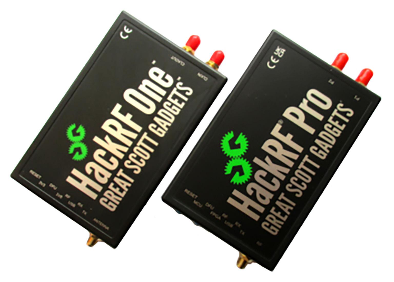
Both devices have exactly the same connectors and controls. And they are compatible enough to be used with the same software. The differences between the two concern internal details, which result in improvements to some features on the HackRF Pro (Chapter 4.4).
There are three RF connectors. On the left, you’ll find a single SMA jack for connecting an antenna. The two SMA jacks on the right are used to connect an external clock source and to synchronize the clock between two devices. They were never used in this book, which is evident from the fact that they still have their red protective caps in the photo.
On the right is also the USB port; on the HackRF One it is a Micro USB port, and on the HackRF Pro it is the newer USB-C.
Figure 1.1 HackRF One and HackRF Pro
On the left side, there are two push-button switches. The reset switch at the very edge can be helpful if an experiment causes a crash. The switch labeled DFU is only used if the device’s firmware needs to be reloaded at some point.
There are a total of six LEDs on the left side. They have different labels but the same functions
connection is active
Transmitter active
If you only connect a power supply or a power bank, the first three LEDs indicate that the HackRF is ready, but nothing else happens. It can therefore only become active when connected to a PC.
So, connect the USB cable to a PC. Now the USB LED also lights up, indicating the connection. But the HackRF is still waiting for commands from the PC. Only when compatible software is launched can it operate as a receiver (RX) or transmitter (TX), indicating this via the corresponding LED.
Usually, you’ll want to test the receive functions first. SDR Sharp (SDR#) is ideal for this. The software is provided free of charge by Airspy (www.airspy.com/download) and works with a wide variety of devices. So you need to select HackRF and can then choose to use either the One or the Pro. More details can be found in Chapters 3 and 4.
If you want to not only receive but also transmit, you should install RadioConda (www. factorialabs.com/radioconda). This allows you to send commands to use either the receiver or the transmitter. More details can be found in Chapter 5.
With RadioConda, you also have GNU Radio installed. This allows you to develop your own software for receivers and transmitters. Details and applications using GNU Radio can be found in Chapters 6 through 11.
For much more information on using HackRF, programming with GNU Radio, and the specific details, additional applications, and hardware of the devices, visit the manufacturer Great Scott Gadgets (www.greatscottgadgets.com/sdr).
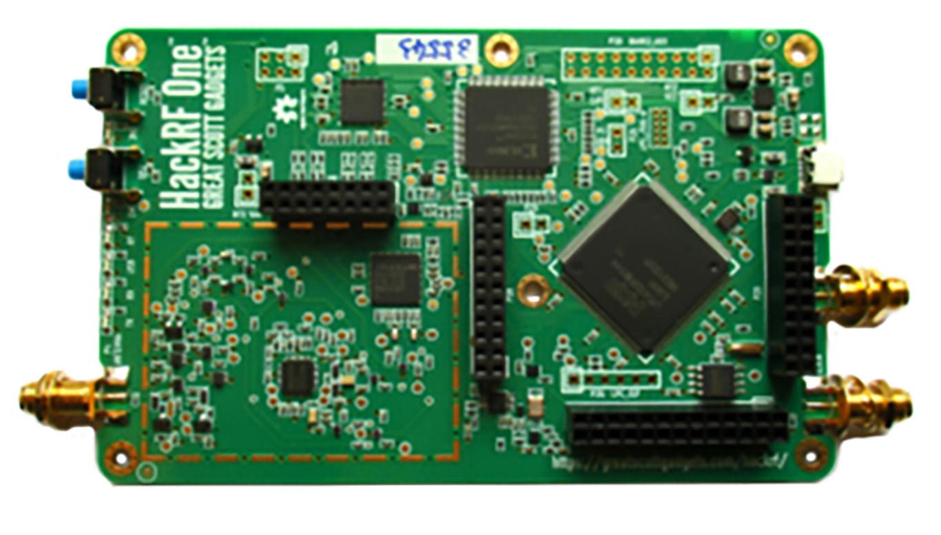
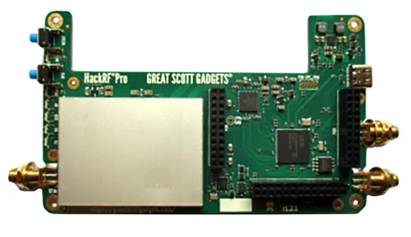
Figure 1.2 HackRF One board
Figure 1.3 HackRF Pro board
Chapter 2 • From Crystal Radios to SDR
Many functions of a software-defined radio—and thus also of a HackRF—are better understood against the backdrop of analog radio technology. Therefore, a brief overview of its development will be provided here.
2.1 Crystal Radio
The first and simplest radio receivers were crystal radios, mostly for medium wave. The desired selection is achieved using a resonant circuit consisting of a coil and a variable capacitor. With a variable capacitor up to 320 pF and a coil with 300 µH, the entire medium wave range can be covered.
This radio does not have very high selectivity and does not yet reach the maximum possible volume. Careful tuning of the antenna and rectifier is important, which can be achieved by tapping the coil.
2.2 The Audion
The audion circuit is characterized by the fact that demodulation and amplification are achieved simultaneously with just a single tube. This results in better overall sensitivity and more gain.
Figure 2.1 Crystal radio with resonant circuit
Feedback brought a further improvement. This allowed RF energy to be fed back into the resonant circuit to compensate for losses and achieve better selectivity. Feedback means that the RF signal is amplified and then fed back to the resonant circuit in phase. The same principle is also applied in an oscillator. In the audion, however, one works either with variable coupling or with variable gain, allowing the degree of feedback to be adjusted. Just before the circuit begins to oscillate on its own, this results in maximum amplification of weak RF signals.
Figure 2.2 A simple tube audion
Figure 2.3 An Audion with feedback
2.3 The Superheterodyne
A single-stage receiver with only one resonant circuit always has a bell-shaped selection curve with low slope. However, to receive a weak transmitter next to a strong station, a more rectangular selection curve with a steep slope is required. This led to the development of the superheterodyne. It uses an intermediate frequency amplifier with multiple bandpass filters.
Mixing stages convert received frequencies to other ranges. In a superheterodyne, the mixer is used to convert the received signal to the intermediate frequency. A direct mixer, on the other hand, converts the signal directly to the audio frequency range. Direct mixers are used, for example, in simple amateur radio applications.
A mixer stage converts the input frequency to the intermediate frequency. The input signal and the oscillator signal are multiplied, producing two mixed products (f1+f2 and f1-f2). If you want to receive exactly 600 kHz, the oscillator is set to 1045 kHz. This creates a second reception point at 1490 kHz. However, because the input circuit is tuned to exactly 600 kHz, this image frequency is strongly suppressed. In the shortwave band, the image frequency is relatively closer to the reception frequency, so there are greater challenges with image frequency suppression.
2.4 IQ-Mixer
In analog radio technology, complex resonant circuits and filters are used to mitigate the problem of image frequencies. This highlights a major advantage of SDR technology, which achieves image frequency suppression entirely without selection means. The key difference is that two separate receive paths with their own mixers are used, which differ in phase by 90º. The two paths are designated as I (in-phase) and Q (quadrature). Through digital processing, the two image frequencies can thus be separated.
This principle is now widely used and is also suitable for hobby projects. The mixers used consist, for example, of four analog switches in the 74HC4066, which ensure good synchronization between both channels and offer high signal immunity. Two analog switches are connected to form a two-way switch, allowing for the implementation of a balanced mixer. An RF oscillator with two outputs shifted by 90º is required for control.
Figure 2.4 Block diagram of a medium-wave superheterodyne
The down converted I and Q signals are digitized via the stereo inputs R and L using a sound card and then processed with SDR software such as SDR Sharp. The actual filtering and demodulation are then handled by the software. This allows you to build a receiver with excellent performance using a very simple front end. At first, how all of this works seems like magic. But later in this book, things will become clear as you develop your own SDR programs using GNU Radio.
Figure 2.5 I/Q Mixer 500 kHz to 30 MHz
Simboli
A
AD converter 87
ALC 89, 111
alias signals 27, 36, 37
AM aeronautical radio 15, 27
AM demodulator 89
Amplitude Modulation 56, 57, 59
AM receiver 89, 90
AM Test Transmitter 103
AM Transmitter 105
Antenna attenuator 90
Antenna input 84, 106, 107, 109
Antenna noise 86
Antenna port power 43
Audion 11, 12
Automatic gain control 89
Aviation weather service 92, 93
B
Baby monitor 35
Balanced mixer 13, 58, 61
Band-pass filter 70
Baseband amplifier 45, 84
Baseband filter 36, 37, 44
BFO 90, 94
Bluetooth 28
Broadcast bands 18, 33, 105
Buffer statistics 43
C
Carrier frequency 56, 58, 62, 93
Carrier level 59, 60, 61
Clock source 8
Common-mode filter 110
Computer Load 87
Continuous Carrier 44
Crystal filter 61, 93
Crystal oscillator 15
Crystal radio 11
CW 19, 20, 91, 102
CW signal 33, 42, 43, 90
D
DAB 37, 78
DAC 43, 44
DC component 106
DC spike 32, 82
Decimation 67, 83
DECT 35
DFU 9
Digital filters 65
Digital modes 20
Digital signal processing 7, 78, 122
Direct mixer 13, 91, 93
Direct Sampling 15, 16
DREAM DRM decoder 22
DRM 22, 23, 29
DSB 61, 62, 120
Dummy load 116, 117
E
ECH81 54
Elektor DRM preselector 29
Elektor SDR Shield 24, 111, 118
End-fed half-wave dipole 114
External clock 8
F
Fast Noise Source 67
Feedback 12, 73, 74, 116
Filter coefficients 67, 71, 74
Filter Design Tool 70, 71, 73
Filter Parameters 76, 80
Filter slope 70, 94
FIR filter 67, 68
FIR Filter 67
Float signals 54, 55
Float to Complex 107
FM band 15, 25, 40, 45, 81
FM demodulator 81, 82
FM radio 36, 82, 105
FM receiver 81, 87
FM Test Transmitter 104, 105
FM Transmitter 78, 107, 108, 121
Frequency accuracy 31, 113
Frequency ranges 15, 33, 89
Frequency Sink 50, 58, 63, 68, 84
Frequency stability 98, 113
FSK 35
FT8 19, 20, 21, 22, 30, 31, 40, 95, 96, 97, 102
Full modulation 99, 107, 117
G
Gain 11, 12, 18, 25, 26, 28, 33, 34, 43, 44, 45, 84, 85, 86, 89, 90, 98, 99, 102, 107, 117, 122
Gate bias 120
GNU Radio 9, 39, 47, 65, 70, 81, 98
GNU Radio Companion 47, 70
GQRX 39
Great Scott Gadgets 7, 9
H
HackRF Controller 25
HackRF environment 42
HackRF FM Receiver 81
HackRF One 7, 8, 9, 10, 24, 27, 28, 31, 81
HackRF Pro 8, 9, 10, 31, 32, 112
hackrf_transfer 41, 42, 44, 45, 46, 98
Harmonics 28, 99, 101, 114
High-pass filter 28
Hilbert transform 63, 110, 114
I
IF gain 98, 107
IIR Filter 73
Image frequencies 13, 15, 28, 55, 82, 89
Image rejection filter 43
Impulse response 73
Interference signals 16, 18, 45
Intermediate frequency 13, 28, 82, 89, 90, 94, 110
Intermodulation products 16, 86
Intrinsic noise 86
I/Q Mixer 14
IQ signals 89
Isolation transformer 103, 109, 110, 116
L
Linearity 117, 118
Local oscillator 43, 90, 93
Low-pass filter 27, 28, 36, 37, 66, 69, 70, 72, 74, 76, 77, 78, 79, 81, 82, 83, 84, 89, 90, 91, 94, 102
LSB 91, 93, 94, 95
LTE 28
M
MAX2837 27, 28, 36, 37, 84
Medium wave 11, 23, 86
Microphone input 105
Mixed products 13, 16
Mixer 13, 14, 15, 16, 17, 27, 28, 37, 50, 51, 54, 57, 58, 61, 63, 82, 84, 89, 91, 93, 110
Modulation depth 60, 61, 99, 103, 118
Modulation frequency 58, 59, 62
Modulation parameters 59
Multiplication 54, 55
Multiply block 50, 110
Multiply Const 89
N
Narrowband FM 15, 104, 105, 121
NBFM Transmit 121
NE612 54
Noise floor 86, 90
O
Oscilloscope 48, 49, 50, 55, 99, 118, 120
Osmocom Sink 98, 106, 110
Osmocom Source 81, 82, 83
Overdrive 17, 34, 86, 121
P
Phantom signals 15, 16, 18, 28, 32
Potential isolation 109
Power amplifier 106, 107, 112, 115, 116, 117, 120, 121
Preamplifier 84, 90
Preselector 16, 23, 28, 29, 30
Q
Q-Branch 15
QT GUI 47, 50, 84
QT GUI Frequency Sink 50, 84
Quadrature Sampling 15, 17
Quiescent current 117, 120
R
Radio beacons 20
RadioConda 9, 39, 41
Rational resampler 81, 83, 107, 110
RDS 40, 41
Receiver overload 86, 90
RF isolation transformer 103, 109, 110, 116
RF power amplifier 115, 116
RTL-SDR V3 15, 16
RTL-SDR V4 17
RX-LNA 45
S
Sample rate 26, 36, 43, 48, 82
SDR Sharp 15, 24, 36, 39
Shortwave AM Receiver 89
Shortwave Receivers 89
Shortwave Reception 17, 29
SiC FET 116
Signal delay 79
Signal Gain 84, 90
Signal Source 43, 48, 49, 62, 65, 67, 98, 117
SMA jack 8
Software-defined radio 7, 11, 31, 55
Spectrum analyzer 99, 100
SSB 19, 61, 62, 63, 64, 90, 91, 92, 93, 94, 96, 102, 110, 111, 113, 115
SSB Filter 93, 94
SSB Generator 110
SSB Reception 90
Superheterodyne 13, 28
Swap IQ 53
Synchronization 13
T
Taps 68, 70, 71, 73, 74, 76
TCXO 31
Test transmitter 45, 98, 103, 104, 105, 117
Throttle block 67, 87, 88
Time Sink 48, 58
Transceiver 91, 93, 109, 121
Two-tone generator 117
Two-tone test 117
TX amplifier 107
U
USB-C 8
USB cable 9
USB mode 92
USB port 8
V
VB Virtual Audio Cable 107
VFO 91
Virtual audio cable 20, 22, 108
Volmet 92
Voltage spikes 34, 103
W
Waterfall plot 19, 40
Waveform generator 48
WBFM Receive 81
WBFM Transmit 104, 121
Wideband FM 81
Wi-Fi 28
Wireless thermometer 15
WSJT-X 20, 96, 97
WSPR 102, 112, 113, 114
WSPR Beacon 112
SDR with HackRF One & HackRF Pro
Programming with GNU Radio
HackRF is an open-source hardware platform developed by Great Scott Gadgets and serves as a versatile front end for software-defined radio (SDR). With HackRF One and its successor, HackRF Pro, users can develop their own SDR applications, build powerful receivers and transmitters, and tackle demanding RF measurement tasks.
This book provides a practical introduction to the world of SDR. Step by step, the author shows how powerful SDR projects can be implemented with HackRF – from the fundamentals of RF technology to advanced applications using GNU Radio.
In addition to working with SDR Sharp (SDR#), RadioConda, and GNU Radio, the book also covers the fundamentals of modern digital signal processing. Numerous experiments and easy-to-follow practical examples guide readers through topics such as AM, FM, and SSB reception, digital filters, shortwave radio, amateur radio, signal generators, and custom RF projects up to 6 GHz.
Whether you are a maker, radio amateur, electronics enthusiast, or SDR beginner, this book provides solid knowledge, practical applications, and the motivation to creatively explore the possibilities of modern SDR technology.

Burkhard Kainka (1953), a ham radio operator with the callsign DK7JD, worked for many years as a physics teacher. Since 1996, he has worked as an independent developer and author in the fields of electronics and microcontrollers. He runs the websites www.elektronik-labor.de and www.b-kainka.de, where he shares his contributions to the Hobby Corner and his passion for the fundamentals of electronics.
Elektor International Media www.elektor.com