LEDs, Lasers, and Sunlight
Principles, Design, and Real-World Applications of Modern Photonics
Miklós Lambert

Miklós Lambert
● Miklós Lambert

This is an Elektor Publication
Elektor is the media brand of Elektor International Media B.V.
PO Box 11, 6114 ZG, Susteren, The Netherlands
Phone: +31 46 4389444
• All rights reserved
No part of this book may be reproduced in any material form, including photocopying, or storing in any medium by electronic means and whether or not transiently or incidentally to some other use of this publication, without the written permission of the copyright holder except in accordance with the provisions of the Copyright Designs and Patents Act 1988 or under the terms of a licence issued by the Copyright Licencing Agency Ltd., 90 Tottenham Court Road, London, England W1P 9HE. Applications for the copyright holder's permission to reproduce any part of the publication should be addressed to the publishers.
• Declaration
The author and publisher have made every effort to ensure the accuracy of the information contained in this book. They do not assume, or hereby disclaim, any liability to any party for any loss or damage caused by errors or omissions in this book, whether such errors or omissions result from negligence, accident, or any other cause.
The author expresses his sincere gratitude to Arrow Electronics and Trenz Electronic for granting permission to include various tables, figures, and program codes in this book.
• ISBN 978-3-89576-742-5 (eBook)
© Copyright 2026 Elektor International Media www.elektor.com
Editor: Clemens Valens
Prepress Production: Patrick Wielders
Elektor is the world's leading source of essential technical information and electronics products for pro engineers, electronics designers, and the companies seeking to engage them. Each day, our international team develops and delivers high-quality content - via a variety of media channels (including magazines, video, digital media, and social media) in several languages - relating to electronics design and DIY electronics. www.elektormagazine.com
4.4.3.
4.5.
4.5.2.
4.6.5.
5.6.1.
5.6.7.
5.7.
5.7.1.
5.8.
8.1.
8.2.
8.5.
8.5.1.
8.5.2.
The basic way of human thinking is connected to the material world: what we eat, drink, and work with; the tangible objects of the universe; their movement, their interactions; and the events of our everyday lives. The basic energy behind all of this is provided by radiation in our case, the radiation of the Sun. With our eyes, we perceive the visible light range, although as we know this range is much wider than what we can see. The basis of the living world (including that ofhumans)is the energychain basedonphotosynthesis, the foundationofwhich is solar radiation.
In the universe, there is constant movement due to the interactions of matter and energy. Energy is characterized by the mass and movement of matter (Einstein).According to the current state of science, radiation is generated by the interactions of matter particles, namely the strong, electromagnetic, weak, and gravitational interactions. These are discussed in physics books. In our everyday lives, we mainly encounter electromagnetic radiation, the characteristic range of which is the light wave, and within this, only a narrow frequency range is visible to the human eye. The energy-carrying particles of light are photons, which can produce effects when they collide with other material particles this is what we deal with in this book. In the radiation ranges known from physics, we also encounter cosmic radiation, radioactive radiation, and Xray radiation, as well as related particles and energy forms; however, these are not the subject of this book.
Light radiation is therefore the movement of energy-carrying photons. We humans (who, according to current knowledge, are the only ones capable of understanding and describing thesephenomenaat this level) continuouslystrive to learn about radiation. Withourstill modest but constantly developing tools, we are increasingly able to use these effects for practical purposes.However,theresultsdonotalwaysbenefithumanityasawhole,andtheinterpretation of concepts such as “weapon” is a philosophical question rather than an engineering one.
The most familiar form of radiation in everyday life is light, whose primary source is the star we call the Sun, where it is produced by large-scale atomic processes.According to the current state of science and technology, we can also generate such radiation on a smaller scale and, when necessary, replace the missing effects of sunlight.
Part of the radiation spectrum is the range called light, only a small portion of which is visible to the human eye, while the sensory systems of other living beings may be tuned to different wavelength ranges. The visible light range serves human vision. In its “white” form, containing allwavelengths, weuseitforillumination,andwereproduceitartificiallywhennaturalsunlight is unavailable.
Throughout history, humans have used various radiation sources for lighting, starting from combustion-based light sources (thermal radiation), through gas-discharge light sources, to modern semiconductor-based emitters such as LEDs and lasers. I have discussed the widely used LED light sources in detail in my book LED Lighting. In this book, I focus on radiation sources developed for purposes other than human lighting, as well as their application technologies. This specific wavelength range, its physiological effects, technical solutions, and application areas have not yet been covered in a unified way in the literature in our country, and
therearerelatively fewexamples internationallywheremeasurementtechnology,healtheffects, and laser technology are treated together.
This book covers the technology of LEDs made from monocrystalline and organic materials, as well as semiconductor lasers that are not used for lighting purposes.
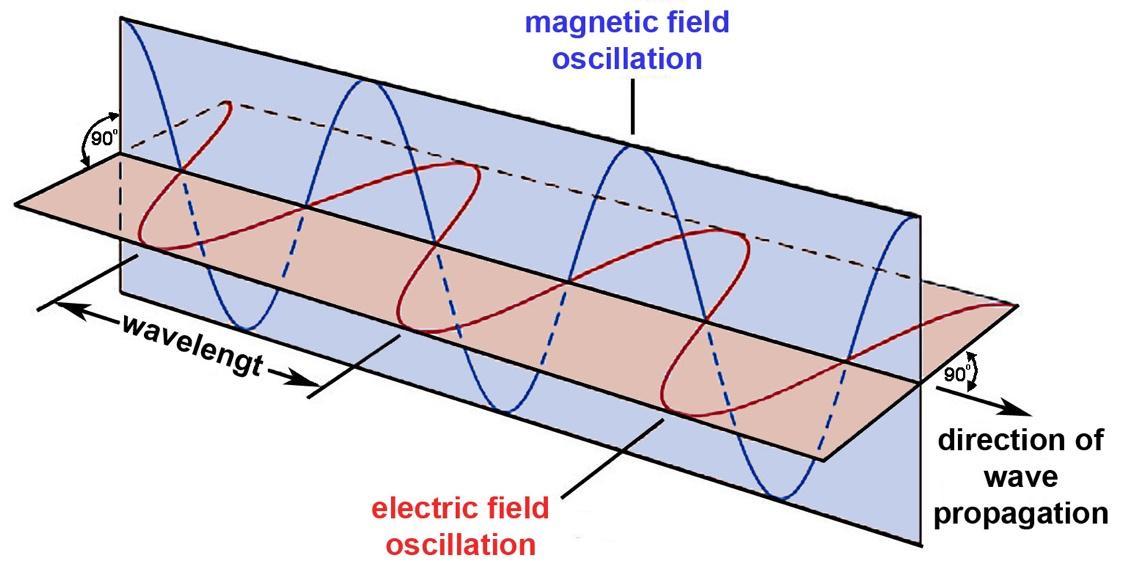
As is known, electromagnetic radiation is the radial propagation of photons, in which the electric field and the magnetic field propagate in planes perpendicular to each other. Its waveform is sinusoidal, and its frequency range extends from almost 0 Hz (i.e., a “straight” wave) to more than 10²⁵ Hz.
The spectrum of electromagnetic radiation consists of transverse waves, meaning that the oscillation is perpendicular to the direction of propagation (as opposed to longitudinal waves, where the oscillation is in the direction of travel), as shown in Figure 1-1. It extends from longwave radio frequencies to γradiation, with asmall middlepartcorrespondingto thevisiblelight spectrum (for the human eye).
Whitelight,whichweuseforlightingpurposes,canbeproducedfrom amixtureofwavelengths in the range of approximately 380…700 nm. This is the domain of lighting technology, where different compositions result in different types of light (cold white to warm white). We will not deal with this topic here, except for the visible wavelengths used for growing plants.
Electromagnetic radiation propagates in a vacuum at a speed of 299,792,458 m/s. This speed is lower in air and in light-conducting materials, where the laws of optics (refraction, reflection, etc.) apply. These topics are discussed in detail in LED Lighting (and in many other sources).
If we examine the spectrum, we find the ultraviolet (UV) range at higher frequencies, and the infrared (IR) range at lower frequencies (towards thermal radiation).
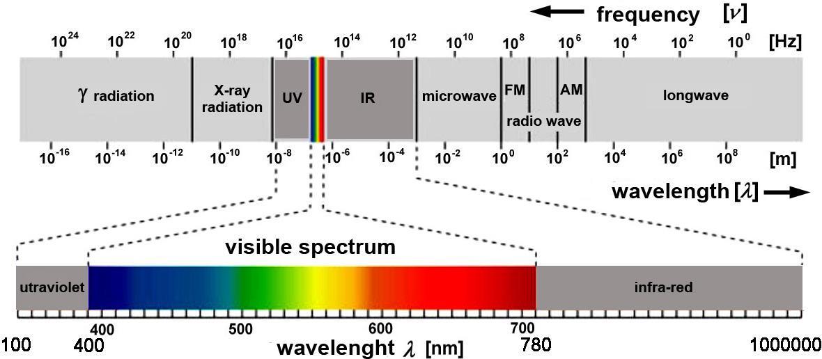
Asis known,light in the ordinarysenseis electromagneticradiation,ofwhichoureyes perceive wavelengths in the range of 380…700 nm. The vision of animals may differ from this to a certain extent. In physical terms, the infrared and ultraviolet ranges are usually also included in the spectrum. Both ranges are further subdivided intoA…C bands, the boundaries of which are not strictly defined. Table 1-1 presents the corresponding data.
Ultraviolet ranges
UV-A 315…400 nm pigment formation
UV-B 280…315 nm Making vitamin D
UV-C 100…280 nm dangerous, carcinogenic
Infrared ranges
IR-A 780…1400 nm close infrared
IR-B 1400…3000 nm middle infrared
IR-C 3000…1000000 nm far infrared
Table 1-1. Invisible light wavelength data.
The infrared, visible, and ultraviolet ranges are collectively referred to as the optical spectrum. Strictly speaking, only radiation in the visible range is called “light”, although some animals can perceive parts of the spectrum that are invisible to the human eye.
Light radiation, propagating as photons, has another interesting property related to the plane of propagation. This phenomenon, known as polarization, is mainly relevant in the visible range and is treated in detail in optics [21]. However, for the sake of completeness and to better understand the use of polarized light in other fields we briefly summarize the relevant relationships (see Fig. 1-2).
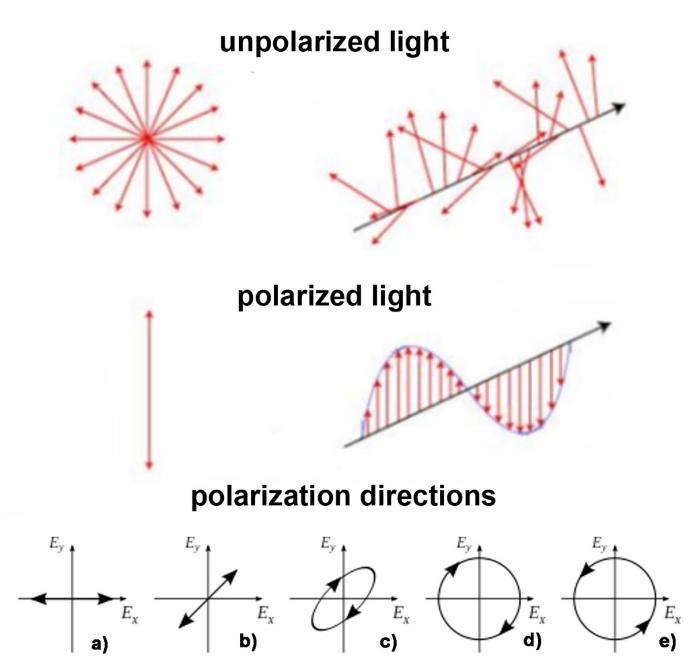
Natural light is not polarized, i.e., its oscillation occurs in arbitrary planes perpendicular to the directionof propagation. Byconvention,the plane ofpolarizationis defined bythe electric field.
The polarization of light that is, restricting it to a single plane can be achieved using a polarizing filter. This has wide applications in optics, whereas the polarization of invisible radiation has relatively few practical applications. Laser light, on the other hand, is polarized; this will be discussed in Chapter 7.
Thereareseveraltypesoflightpolarization.Inthelowerpartofthefigure,fivecasesareshown. The first two represent linear polarization, while the others represent circular polarization. In Figure a), linear polarization occurs when the waves in the light beam have the same amplitude and phase (Ey = 0, only an Ex component is present), and their planes coincide. In Figure b), the two components have equal amplitude, but their planes form an angle of 45°; this is referred to as horizontal and vertical polarization.
Figures c)…e) show circular polarization, in which the wave components also form an angle, but their phases differ. In this case, the plane of polarization rotates, resulting in a rotating electric field. In the general case, this is called elliptical polarization, as shown in Figure c). When the phase difference is 90°, the polarization becomes circular, rotating to the right as in Figure d), or to the left as in Figure e).
Although not intended forillumination, devices operatingin thevisiblelight range arealso used for signaling purposes (traffic lights, signal lamps, illuminated switches, etc.). With some leniency, these can be classified as lighting devices.
An electromagnetic wave propagates in two mutually perpendicular planes, both perpendicular to the direction of propagation.The electric and magnetic fields are in phase, and the waveform is sinusoidal, as shown in Figures 1-3.
The theory of electromagnetic waves was described by Maxwell.The differential equations can be found in the literature; if we ignore them, the four basic principles of their interaction can be formulated in text as follows:
•The force of attraction or repulsion between electric charges is inversely proportional to the square of the distance between them.
•The components of electromagnetic waves interact: a changing electric field creates a magnetic field, and a changing magnetic field creates an electric field.
•An electric current flowing in a conductor creates a magnetic field, the direction of which depends on the direction of the current.
•There are no magnetic monopoles; magnetic poles always occur in pairs and attract or repel each other similarly to electric charges.
Several sources of electromagnetic radiation are known. Natural cosmic solar radiation is considered fundamental, but radiation can also result from particle collisions causing ionization in space (although this is a rare natural phenomenon). An example is the “northern lights”, visible mainly in regions beyond theArctic Circle. This is not considered a radiation source for lighting purposes. Similar effects include the light emitted by flowing lava during a volcanic eruption, electrical discharges between clouds (lightning), and the chemically generated light of certain underwater animals or insects (fireflies). These phenomena also do not belong to the category of lighting devices.
The infrared range, which corresponds to thermal radiation, occupies a special place. Whether originating from natural processes (e.g., the warming effect of the Sun) or artificial ones, temperature differences arise between materials, resulting in the transfer of thermal radiation from warmer to cooler regions.Although this is not a radiation source for lighting purposes, it is an important area that will be discussed in Chapter 3.
Humans have been generating electromagnetic radiation since prehistoric times, initially for lighting and heating, and today for many other purposes. But what tools are used to produce such radiation? These will be discussed below.
Fire is an ancient tool, created by the combustion of materials in the presence of oxygen. From a modern perspective, it is the most primitive method, although it is still used today for heating in stoves, fireplaces, and boilers. Its use for lighting is now negligible, although candles and kerosene lamps still exist as emergency lighting or for decorative purposes (e.g., candlelight dinners or “safety” lighting in wine cellars). Their emission spectrum lies in the warm region of visible light, and we will not deal with it here.
The technology of the 21st century is electricity, and today electromagnetic radiation is mainly generated by electronic devices. Therefore, in terms of radiation sources, we focus on such devices, including modern (primarily semiconductor-based) emitters covering nearly the entire wavelength range.
Although modern electronics has produced highly complex integrated circuits, the simplest device the diode is still widely used to generate electromagnetic radiation. Two fundamentally different devices are the LED (Light Emitting Diode) and the laser diode. The former is typically based on a semiconductor crystal, although organic variants (OLEDs) are also rapidly developing. In the field of lasers, earlier versions were based on ionized gases, followed by liquids, solids, and even plasma. Today, semiconductor lasers are among the most promising and versatile, although in some respects they still lag behind earlier types, which is why many laser variants exist (see Chapter 7). LEDs cover a wide portion of the electromagnetic spectrum, and lasers have also advanced significantly. However, in practical applications, the decisive factors are often not the wavelength range itself, but the physical and technical parameters.
Radiation phenomena are treated in physics, often with the support of mathematics. The reader can find the necessary background in the literature, along with the material constants required for calculations. The notation and units used are generally consistent across the literature. In this book, these are summarized in theAppendix.
Initially, light was interpreted simply as radiation (later as electromagnetic radiation), but it became clear that when it interacts with matter, effects occur that could not be explained by this view alone. The wave theory of light could account for phenomena such as interference, diffraction, and polarization, but it did not explain interactions arising from collisions with electrons at the surface of materials.
This led scientists notably Albert Einstein in 1905 to conclude that light possesses not only wave-like (radiation) properties but also particle-like properties. The particles of light are called photons, representing the quantum of light energy. These photons propagate in a wavelike manner, and their energy depends on the frequency of the light.
We also encounter the phenomenon that the particles of light do not behave like classical material particles in collisions with electrons. For the sake of distinction, other quasi-particles involved in matter interactions are referred to as phonons. These phenomena are treated in the field of quantum mechanics. The reader can find extensive literature on this subject, but for the sake of understanding the following sections, we summarize the basics here.
In addition to the optical (wave) properties of light, its particle-related properties are also important:
•absorption and emission
•the photoelectric effect
•the Compton effect, according to which the energy of a photon is E = h·v, where h is Planck’s constant and v is the frequency of the light
Our book mainly deals with light effects based on these phenomena. These occur when photons reach the surface of a material: part of the radiation penetrates into the material and is absorbed, while another part is reflected at the interface.
Planck’s constant is one of the fundamental constants of quantum mechanics. It is named after Max Planck, who played a key role in the development of this field. Its value is:
h = 6.62607015 × 10⁻³⁴ J·s = 4.135667696 × 10⁻¹⁵ eV·s
The value of Planck’s constant emerged from studies of blackbody radiation, which showed that energy transfer occurs in discrete quantities (quanta). This marked the beginning of quantum mechanics, extending beyond classical mechanics, and is worth a brief explanation.
In simple terms, Planck’s constant can be interpreted as energy multiplied by time, which corresponds to the physical quantity known as action. It can also be expressed in equivalent units, such as momentum multiplied by distance.
Planck originally introduced this constant in the context of blackbody radiation, where he had to assume that energy exchange occurs only in discrete amounts.
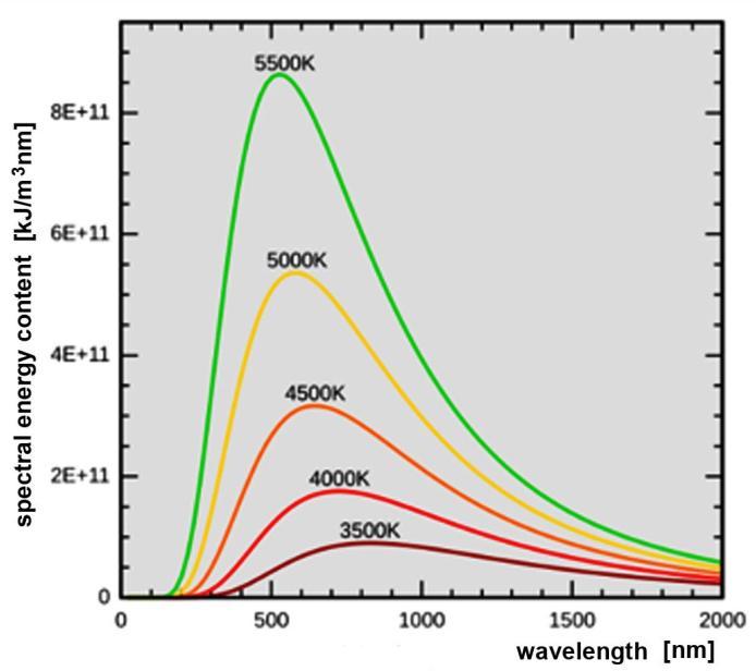
Figure 1-4. Intensity of light emitted by a black body. Each curve represents the behavior at different body temperatures. Planck's constant h is used to explain the shape of the curves.
Visually, Planck's constant gives the energy of a 1 Hz photon, which also appears during the photoelectric effect. Light of a given frequency ν consists of photons of a given energy E: �� =ℎ∙�� (1-1)
It is often more convenient to write this with the circular frequency ω=2π·ν, from which �� =ℏ∙�� (1-2)
where ħ is the reduced Planck constant, or also known as the Dirac constant (pronounced: hstroke):
ħ=h/2=1.054571817…·10-34[J·s]=0.6582119569… [eV·fs]
In physics, energy is a physical property of bodies that can be transformed into different forms of manifestation and transferred between bodies by the four fundamental interactions, but it cannot be newly created or destroyed, i.e. the total energy of an isolated system remains constant.
The joule [J] is the SI unit of energy, defined as the energy transferred to a body by a displacement of 1 meter by mechanical work against a force of 1 newton.
In practice, the following terms are used to name energy: ability to do work, ability to interact, ability to change the state of a body or field.
Commonly used terms related to the concept of energy are: energy saving, energy carrier, energy use, energy conservation, energy development, energy poverty.
Theoretically, energy forms can be traced back to one of the four fundamental interactions of physics. Kinetic and potential energy can come from any of the fundamental forms, potential energy is the stored version, kinetic energy is the released version of energy. Thermal energy
comes from the kinetic energy of molecules. Kinetic energy is a type of energy that can be used directly by humans, because the rotation and progress of their machines are the form that performs actual useful actions. The four basic interactions are gravitational, electromagnetic, weak and strong interactions.
In terms of practical application, names that differ from the theoretical ones are also used, e.g.: gravitational, potential energy, position energy, heat energy, thermal energy, motion or kinetic energy.
Gravitational interactions
For example, a hydroelectric power plant converts the gravitational energy of a river into the motion energy of turbines, which is converted into electrical energy in generators. Pumps powered by electricity pump water into water towers, storing the energy needed to distribute the water in the public utility network in the form of gravitational energy.
Electromagnetic interactions
Mostly, electromagnetic energy drives our machines and operates our electronic systems. Electromagnetic energy can be a source of heat engines and internal combustion engines, in which the heat energy comes from combustion, i.e. a chemical transformation, which is a transformation related to the electronic structure of atoms and molecules, i.e. an electromagnetic process. For living beings, chemical processes, i.e. the electromagnetic interaction, also provide energy storage and energy use, so biological energies are also of electromagnetic origin.
Weak interactions
The energy from the processes of the weak interaction, from weak radioactive decays (beta decay), partly maintains the high internal temperature of the Earth, so geothermal energy is also fed from this source. Gravity also raises the internal temperature of the Earth through tidal forces.Asmaller part of the Sun's energy production also comes from weak processes.
Strong interactions
The strong interaction holds atomic nuclei together. When atomic nuclei merge, a large amount of energy corresponding to the binding energy is released. Such nuclear fusion is responsible for most of the energy production of the Sun and stars.
Asweknow, electrons in atoms ofmattercanresidein discreteenergylevels. During absorption, the atom absorbs a photon, so one of its electrons goes from a lower energy state to a higher energy state. However, this state is not stable, and the atom, in accordance with the principle of the energy minimum, strives to reach the lowest energy state, the ground state. The opposite process to absorption is spontaneous emission, when the atom goes to a lower energy state without any external influence, and the atom emits a photon with an energy equal to the difference between the two energy levels. These transitions are characteristic of the given material, which emits photons at wavelengths characteristic of them when excited.
Figure 1-5 shows that the spontaneous band change of the electron manifests itself in photon radiation, the energy content of which can be calculated using Planck's constant.
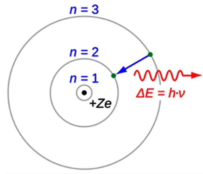
Figure 1-5. Schematic representation of the Bohr model of the hydrogen atom. The transition from the n = 3 level to the n = 2 level results in visible light with a wavelength of 656 nm (red), as predicted by the model
The phenomenon is shown by the band model in Figure 1-6.
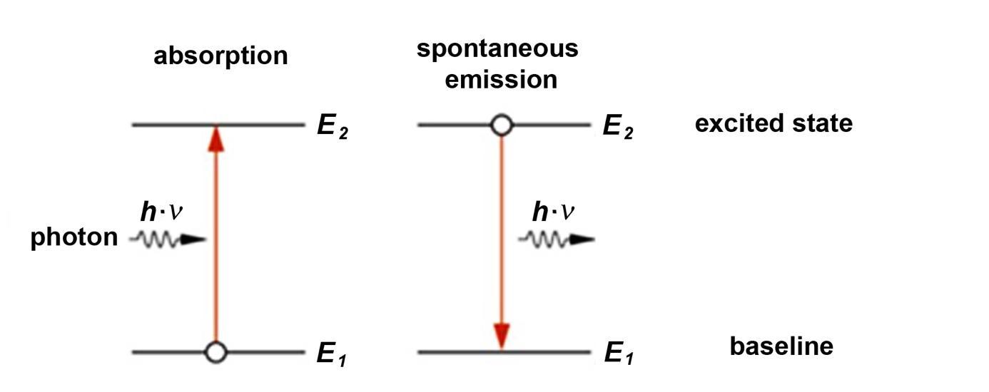
Figure 1-6.Absorption and spontaneous emission
During spontaneous emission, the energy of the emitted photon is therefore equal to the difference between the energies of the two levels: ��2 +��1 =ℎ∙�� (1-3)
In electromagnetic radiation, in addition to spectral aspects, the energy of the photons is fundamental, which is why we distinguish between ionizing and non-ionizing radiation. The former are able to bombard the atoms of the material in the path of the radiation, and the collisions can lead to the production of additional photons or material transformations. This is the phenomenon of induced emission, the basis of the operation of lasers, which we will discuss in more detail in Chapter 7.As a summary, Table 1-2 shows the Planck constants.
Table 1-2. Values of Planck's constants
Wavelengths of light outside the visible spectrum were discovered in the early 19th century. William Herschel described infrared radiation in 1800. Johann Wilhelm Ritter discovered ultraviolet radiation in 1801. Both scientists used a prism to detect light to break sunlight into its component wavelengths. The equations describing electromagnetic fields were developed by James Clerk Maxwell in 1862–1864. Before James Clerk Maxwell's unified electromagnetic theory, scientists believed that electricity and magnetism were separate forces.
Einstein put things in their place in 1917, with his theory of stimulated emission, which was put into practice(i.e.,thecreationofalaserbeam)in thelate1950s.This theorylaid thefoundations of laser operation, which we will discuss in Chapter 10. Scientists at the turn of the 20th century restored the foundations ofelectromagneticradiation,with Max Planckbeingoneoftheleading scientists.
Science has long been concerned with the laws of light propagation, and attempts have been made to explain them for a long, long time. One of the oldest theories was put forward by the great Greek philosopher Democritus (470-378 BC). According to him, light consists of numerous, infinitely small atoms.About 500 years later, Hero, also a Greek, wrote a book about mirrors and the law of reflection, thereby creating the model of geometric optics. Although many more theories were developed after that, no real development took place until the 17th century.
As is known, when light reaches the boundary between two optically different media, it undergoes refraction. Although the Arabs had already recorded the angle of refraction for different values of the incident light ray in tabular form, and they also knew the angle functions, the relationship between the two angles was only discovered in 1621 by the Dutch mathematician Snellius, which laid the foundation for further scientific findings.
Isaac Newton (1642-1727) greatly improved the corpuscular theory of light, and discovered and studieddispersion. However,theexplanationofoptical phenomenain termsofvariouslight particles later proved to be a mistake.At the same time as Newton, the Dutch physicist Huygens (1629-1695) assumed that light is a wave. In many respects, this model is still used today. The
nature of light has been studied by many physicists since then, such as Compton (1892-1962), deBroglie (1892-1987) andAlbert Einstein (1879-1955). Einstein revived Democritus' particle theory, to which Compton contributed significantly with the discovery of the photon. Compton and deBroglie showed that both the wave and particle models are necessary to describe the behavior of light.
The history of the discovery of semiconductor light generation is still ongoing today, and the literature is abundant. The reader will find further references in the chapters, especially the history of research in lighting technology is spectacular (see Chapter 2.2), here we have only outlined the beginnings, which laid the foundation for the history of radiation as a scientific discipline.
Today's research goes beyond this. In addition to traditional "macro" light generation, "micro" physics, which is discussed in quantum physics, is increasingly coming to the fore, and laser operation can be explained more by this (see Chapter 10).
In this book, we deal with light, which is a fundamental aspect of our everyday lives. However, in order to interpret phenomena correctly, it is necessary to understand the underlying physical principles. Much of this knowledge is well known, yet it often happens that incorrect conclusions or misinterpreted laws can lead our thinking in the wrong direction. Although numerous textbooks, onlinesources, andspecializedpublications discuss theproperties oflight, it is useful to present the concepts in a systematic way, so that they can be referred to when describing the operation of new light-based technologies. This chapter serves that purpose.
Light, as an electromagnetic wave, propagates in straight lines, but its behavior is governed by well-defined laws. In the human context, light primarily serves for illumination and vision, but these laws apply to the entire wavelength range. The fundamental relationships are described by the science of optics, which, in principle, applies across the full frequency spectrum.
The universe consists of particles of matter in a vacuum, which possess energy and are in constant motion. During this motion as a result of collisions and other interactions photons are generated, which propagate in the form of radiation. A significant portion of this radiation is electromagnetic in nature, referred to in a broader sense as light, although in everyday usage the term usually denotes only the part perceived by the light-sensitive organs of living beings (eyes).
Inthis book,weconsidertheentirespectrum, not just thevisiblepart.Most radiation propagates through the universe, transferring energy between material bodies (celestial objects), only a small portion of which is visible when we look at the sky.
Human activity (at least for now) is confined to Earth, and our everyday environment is dominated by radiation from the Sun as well as by artificial radiation sources created on Earth. The laws established in this “narrow” environment apply throughout the universe, and their understanding contributes to the progress of exploration on an ever larger scale. For example, future plans may include sustaining plant life on Mars in controlled, photosynthetic environments capable of producing oxygen although this still belongs largely to the realm of science fiction.
The study of radiation is therefore not only theoretical, but a practical necessity.
Electromagnetic radiation is widely used in everyday human life. To do so effectively, it is necessary to understand both the sources of radiation and the methods of its utilization.
In terms of sources, we can distinguish between natural and artificial radiation sources. The primary natural source is the Sun (and, in some cases, other distant celestial bodies, although their practical significance is limited). The task is then to capture and utilize this radiation. The
oldest method is agriculture crop production which forms the basis of human life and is now increasingly supplemented by artificial radiation sources. The use of thermal energy can be considered a traditional application (see Chapter 12), while one of the most modern approaches is the utilization of solar energy based on the photoelectric effect, which will be discussed in more detail in Chapter 11.
The range of artificial radiation sources is much broader, as the intended application determines the device. The development of new (typically semiconductor-based) devices is often the result of extensive research. These are discussed in more detail in the following chapters, particularly in the context of lighting technology.
Photon radiation, as electromagnetic radiation, propagates through the universe and, in everyday terms, appears to travel in straight lines. More precisely, this is strictly true in a vacuum. In practice, radiationalso propagates in air(similarly to vacuum propagation, although with differences on larger scales) and in light-conducting materials, where it may experience losses, be reflected, or induce secondary radiation (e.g., phosphorescence).
The boundary between different media is important, as three processes can occur there:
• part of the radiation is reflected
• part of the radiation is absorbed by the material and converted into heat and/or secondary radiation
• part of the radiation is transmitted into the medium
The terminology related to radiation in physics and technical practice is broad. From a systems engineering perspective, it is important to use terms consistently, as mixing them can lead to misunderstandings.The term photon radiation is therefore appropriate, since, for example, laser radiation is not intended for illumination, infrared data transmission cannot strictly be called light, and ultraviolet radiation is often referred to informally as “tanning light”.
The propagation of photon radiation can be studied in three main application areas, depending on whether we consider macroscopic, microscopic, or quantum-scale phenomena:
• Geometrical (ray) optics is used in the visible range, for example in the study of shadows, mirrors, lenses, and prisms.
• Physical (wave) optics applies to both visibleand invisibleranges, particularlywhen obstacles are comparable in size to the wavelength of the radiation.
• Quantum optics deals with phenomena arising from the interaction of light with matter (e.g., laser diodes, secondary emitters, etc.).
These concepts will be discussed accordingly.
2.3.1. Geometric optics
2.3.1.1. Radiated power, luminous flux
Light is fundamentally a physical quantity. Its laws are described in physics, and therefore its measurement and units are also defined within this framework. In practice, however, lighting technology that is, photometry has developed its own set of concepts and units, largely due to the independent evolution of lighting applications. These are specialized forms of the original physical quantities.
The quantities and units used in both systems are based on the same physical principles. In practice, the SI system of units which is mandatory for IEC standards is generally used, even though catalog data in industry and technical literature may still appear in Anglo-Saxon or other unit systems.
The measurement system used in lighting technology was originally established by the AmericanANSI and remains widely used as a global standard. It is also compatible with the SI system. In contrast, physical units are typically used in laser technology and in other nonlighting applications.
The relevant quantities are summarized in Table 2-1.
Table 2-1. Comparison and units of physical and photometric quantities
We will not deal with the definitions of the terms here, the literature is detailed. The terms are as follows:
• Radiated power, luminous flux [W, lm]
• Solid angle [sr]
• Radiant intensity, luminous intensity, light distribution [W/sr, cd, lm/sr]
• Irradiated, radiated surface power, power density [W/m²]
• Radiated surface luminous flux [W/m²]
• Radiant density, luminous density [W/m²·sr]
• Radiated energy, light quantity [W·s, lm·s]
• Light efficiency [%]
• Irradiated energy, illumination energy [W·s/m², lx·s]
• Total luminous flux of light source [lm]
2.3.2. Wave optics
Most of the laws of light cannot be explained by geometric optics; for this, light must be understood as electromagnetic radiation.
Light is a transverse electromagnetic wave, which means that both the electric field strength E and the magnetic field strength H change periodically in space and time along the propagation of light, i.e. the two field strengths perform harmonic oscillations in a plane perpendicular to the direction of travel (and at the same time to each other), as we saw in Figure 1-3.
Since detectors, including our eyes, detect changes in the electric field strength, the plane of oscillation of light will be understood as the plane of the electric field from now on.
Light has energy content and propagates in a vacuum unhindered and without loss. Space is not a pure vacuum either, but there are very few obstacles in it, which is why light beams reaching us from many millions of light years away are visible in the sky.
The concepts of wave optics are available in the literature similarly to the geometric ones. They are as follows:
• Attenuation
• Polarization
• Absorption
• Emission
• Dispersion
• Scattering
• Diffusion
• Diffraction
2.3.3. Quantum optics
In subsections 2.3.1. and 2.3.2. we discuss light as the energy movement carried by photons as particles, but in reality, light transformations can occur in the visible light range, which are described by quantum optics. Their practical application is primarily in lighting technology, but they are also used elsewhere.
The concepts describing the phenomena are as follows:
2.3.3.1. Luminescence
From the perspective of electron excitation, there are several types of luminescence:
• Photoluminescence: conversion of higher-energy optical radiation into lower-energy radiation (fluorescent tube, secondary-radiation LED)
• Electroluminescence: conversionof electric field energy intolight, chargeinjection(pnstructure LED)
• Cathodeluminescence: conversion of kinetic energy of electrons into visible light (cathode-ray tube, conventional picture tube)
• Chemiluminescence: conversion of chemical energy into light
• Thermoluminescence: heat-induced luminescence
• Triboluminescence: conversion of mechanical work into light
• Sonoluminescence: conversion of sound wave energy into light
• Radioluminescence: conversion of radioactive radiation energy into light
The relationships are illustrated in Figure 2-1.
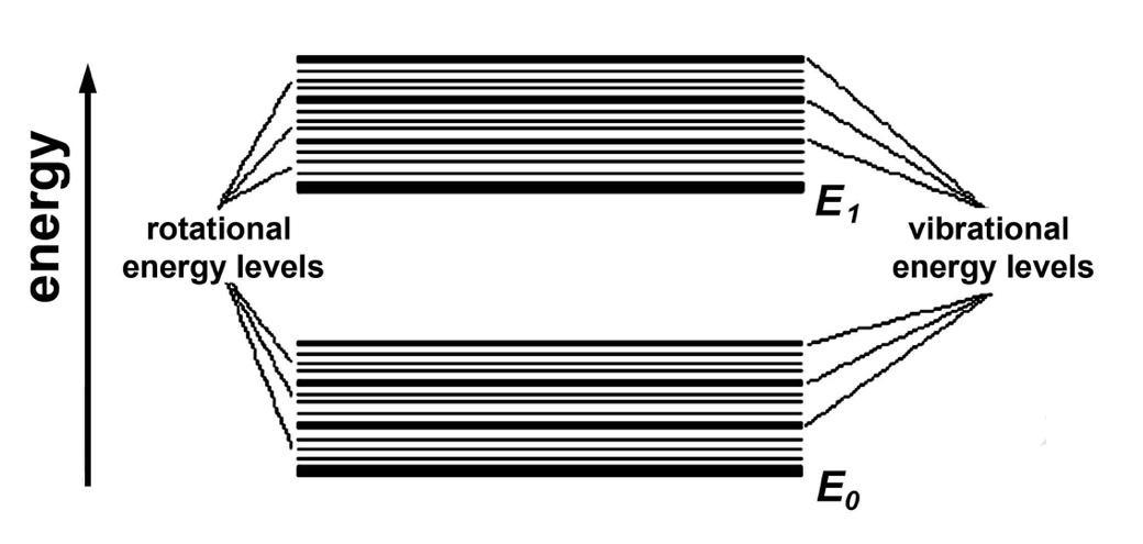
In the ground state, electrons are in a singlet state. The possible bands can be seen in Figure 22. The thick line indicates the electron energy levels, the thin lines indicate the vibrational energy levels.
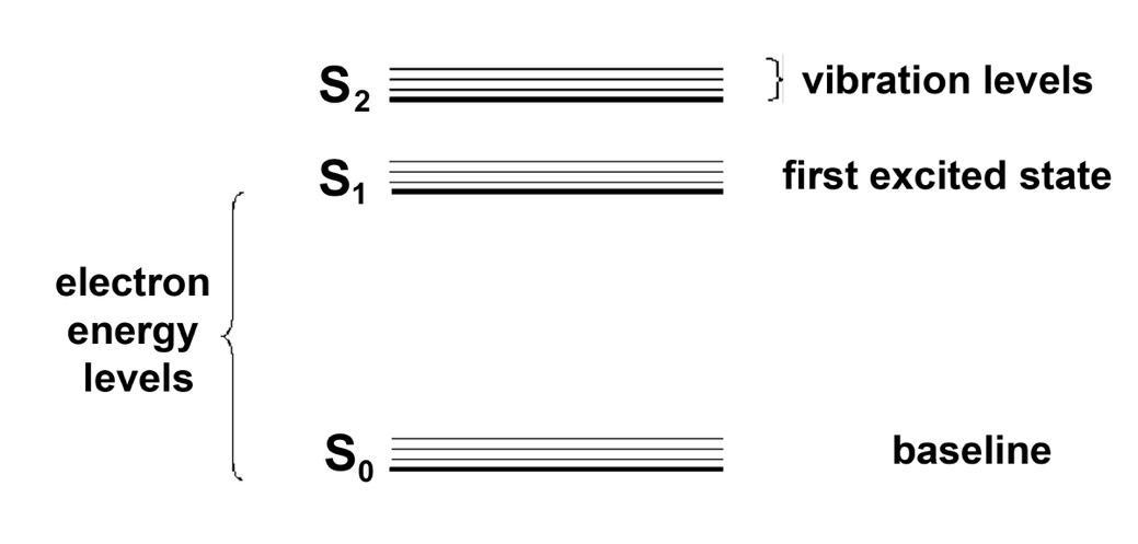
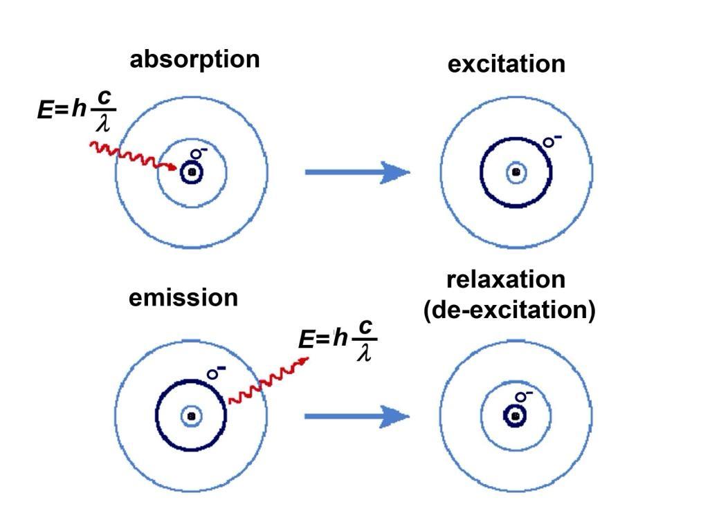
The energy transfer occurs during absorption. The energy level of the excited atom increases, theelectronsmove to a higherorbit, andthen returnto thegroundstate whentheenergy transfer ceases. Both during excitation (excitation) and relaxation (de-excitation), the state and quantum number of the electrons change. The process is illustrated in Figure 2-3.
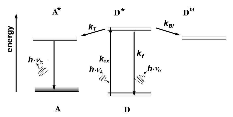
The Jablonski diagram is used to represent the energy levels and states of the excited atom. [153]. The Jablonski diagram illustrates the states of an electron orbital in a molecule and their transitions. The states are plotted vertically as a function of energy, horizontally as a function of spin multiplicity, with the singular state denoted by S and the triplet state denoted by T. Radiation may occur during the state transition, but thermal energy may also be produced instead of photon emission, which is of course a loss. Non-radiative transitions are shown by the wavy arrows, while radiative transitions are shown by the straight arrows. The vibrational ground states of each electronic state are shown by thick lines, and higher vibrational states by thinner lines. A radiative transition involves absorption if the transition occurs to a higher energylevel,orphotonemissioninthereversecase.Non-radiativetransitionscanoccurthrough a number of different mechanisms. The transition of an excited state to a lower vibrational level involves the dissipation of energy to the surroundings, so this cannot occur in an isolated molecule. Another form of non-radiative transition is internal conversion, which occurs when the vibrational state of an electronically excited state couples to the vibrational state of a lower electronic state. The third type is the so-called “intersystem crossing”, when the transition occurs with different spin multiplicities. For molecules with large spin-orbit coupling, the intersystem crossing is more important than for molecules with small spin-orbit coupling. The principle of the Jablonski diagram is shown in Figure 2-4. [153]
In Figure 2-5, the fluorescence phenomenon is depicted on a Jablonski diagram by showing the spin states.
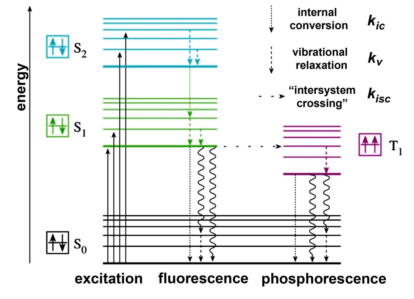
Figure 2-5. Representation of fluorescence and phosphorescence on a Jablonski diagram
2.3.3.2. Fluorescence
Luminescence can also be triggered by light as an energy carrier. This is called photoluminescence or fluorescence. The literature also calls the phenomenon secondary radiation. When the molecules of the fluorescent substance absorb light of a given energy, they
enter a higher energy state, then return to their resting state, but in the process they release some of the absorbed energy in the form of light. Some of the energy is lost during the process (about 20%), the emitted light has a lower energy and a longer wavelength than the exciting light. The processisalso calledfrequencyconversionorwavelengthconversion.Whenthelightexcitation ceases, the fluorescence also ceases. The phenomenon is explained in Figure 2-6.
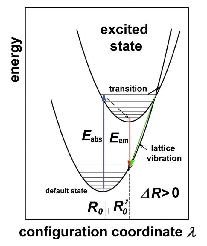
This is of great importance in white light LEDs, where an LED emitting blue or UV wavelengths as a primary is either emitted by the phosphor powder placed in close proximity to it or by the secondary emitting material applied to the surface in the form of a layer, located further away, emitting yellow (i.e. longer wavelength) fluorescent light, the resultant of the two lights is white.
In Figure 2-6, we can see that the energy Eabs of the primary emitter (blue LED) excites the secondary emitter, which emits energy of the magnitude Eem in the yellow wavelength range. Due to the shift in the wavelength range, part of the energy vibrates the atoms, which causes heat loss, and does not excite waves in the visible spectrum.
The loss energy is proportional to the wavelength shift according to the following relationship:
This shows that the loss is smaller, the larger the wavelength shift, so better results can be achieved with a primary light source emitting in the ultraviolet range than with a blue LED. Secondary radiation does not necessarily occur with only one material. Some materials (the socalled anti-Stokes phosphors) absorb the energy of several photons and emit them as a single photon, but the reverse also happens, that a single high-energy photon (e.g. from UV-C radiation) excites several photons of lower energy, even in a stepwise manner (photon cascade), e.g. in the green and red wavelength range. Research is ongoing, behind the appearance of a
LED with a higher lumen/W luminous efficiency on the market is a new abb, higher quantum efficiency phosphor can be used. With correctly selected materials, the energy loss can be kept below 10%, but it is still worth using it, since with the primary emitter we can only obtain white light by the R-G-B color mixing method, which in turn poses serious obstacles when achieving correct color reproduction. It is therefore no coincidence that white LEDs manufactured for lighting purposes use the principle of secondary radiation.
In the fluorescence phenomenon, the molecule or the part of a molecule that is responsible for absorbing light and acts as an emitter in the system is called a chromophore. Fluorescence occurs in four steps. First, the fluorophore molecule (i.e. the molecule or part of a molecule responsible for emitting light) absorbs a photon from the chromophore, enters an "excited" state due to the energy of the absorbed photon, then loses its excitation energy due to molecular collisions, and finally the fluorophore in the excited state returns to its ground state while emitting a photon. The conditions for fluorescence are that there is an "excitable" electron in the outer electron shell of fluorescent substances, and the energy of the "exciting" photon is comparable to the energy difference between the ground state and the excited state of the electron in question. The lifetime of the excited state is 10–9 s (1 ns). During this time, the fluorophore enters into molecular interactions with its environment, which is why it loses its energy. The energy of the emitted photon is therefore always lower and its wavelength is longer than that of the exciting photon. Fluorescence involves a singlet-singlet state transition. We will not discuss the non-radiative state transition in this book, as our goal is to demonstrate the generation of cold light. However, it should be mentioned, as it must be mitigated as a lossy state transition. This mechanism is called Förster resonance energy transfer (abbreviated: FRET) after the German physicist Theodor Förster. Förster resonance energy transfer, after the English Förster resonance energy transfer; is a mechanism that describes the transfer of energy between chromophores. It is sometimes also called fluorescence resonance energy transfer, resonant energy transfer (RET) or electronic energy transfer (EET).
A donor chromophore, in its initial excited electronic state, can transfer energy to the acceptor chromophorethroughnon-radiativedipole-dipolecoupling(thetwochromophoresaretypically 10 nm apart).
The phenomenon of luminescence is used for many purposes in technology. Its traditional field is spectroscopy, even in living matter, where the efficiency of light generation is desirable to be high for the sake of observability. In LED lighting technology, efficiency is of paramount importance, therefore developers are putting great effort into finding suitable materials and phosphors. The phenomenon of fluorescence and phosphorescence has long been utilized by discharge lamps; it is created by electronic state transitions between discrete atomic levels, and the radiation produced has a discrete line spectrum.
From the perspective of white LEDs for lighting purposes, electroluminescence is of greater importance, on which the operation of the light-emitting diode for lighting purposes is based, and although this is also created by excited and relaxed electrons in the process taking place inside the semiconductor crystal, the energy bands occur at the energy levels between the valence and conduction bands, due to the crossing of the forbidden band, it is an almost monochromatic, continuous-spectrum primary radiation, therefore it is explained with the usual relationships for semiconductors. Some electroluminescent materials:
• Zinc sulfide powder doped with manganese
• Zinc sulfide powder doped with copper or silver
• Thin film zinc sulfide, doped with manganese
• Thorium, yttrium, zirconium
• Natural diamond, doped with boron
• Semiconductors such as InP, GaAs, GaN
• Organic semiconductors
Of these, the latter two semiconductor materials are used in LED and OLED technology, while the former are secondary emitting fluorescent materials, which are popular materials for fluorescent tubes and LEDs.
Fluorescent materials are secondary emitting materials, which emit light ofa longerwavelength when exposed to light, and are the materials for white LEDs. Research is also ongoing in this field, and so far four groups of materials are known:
• silicates
• NYAG materials
• GAL materials
• nitrides
2.3.3.3. Phosphorescence
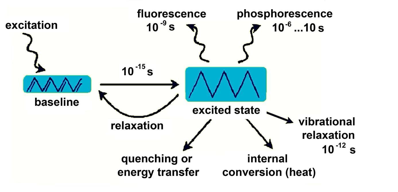
If the secondary light persists (even for minutes) after the light that caused the fluorescence is turned off, then we are talking about phosphorescence. This phenomenon was previously exploited in long-lasting cathode ray tubes, which were the devices of the analog storage oscilloscope. The process of photoluminescence is illustrated in Figure 2-7.
2.4. Optical laws
2.4.1. Refraction
Light propagates unhindered in a vacuum, in a straight line, but – under terrestrial conditions –
italsopropagatesingases,liquidsandotherlight-conductingsolids,butwithlossandaccording to given laws it can change direction, refract, which depends on the wavelength (this is why we see the sky as blue, for example). The physical reason for refraction is that light travels more slowly in a medium than in a vacuum. This is not due to some kind of mechanical resistance, but because the alternating electric field forces the electron shell of the material to vibrate. As we know, vibrating charges emit radiation (with the same frequency as their forced vibration). It can be seen by calculations that the sum of the incoming radiation and the radiation emitted by the vibrating atoms of the medium (the product of the rotating vectors representing the vibrations) in the space after the medium has the same vibration as the incoming radiation, but suffers a phase delay proportional to the thickness of the medium. We perceive this phase delay as if the light had traveled more slowly in the medium. Geometric optics is based on the phenomena of refraction, reflection and transmission, which deals with the laws of the light beam in light-transmitting media and at their boundaries. The first two are characterized by the fact that the direction of the light beam changes at the interface. (A light ray is actually an idealized concept, since if it has no extension, it is not visible, so it is more appropriate to speak of a light beam, which can be understood as a set of light rays traveling together.A light beam can be converging, diverging, and parallel. To explain optical laws, we consider a light beam to be a set of parallel light rays.)
Consider a light ray that, as described above, propagates in a straight line until it reaches the boundary of a body or a different medium. If the surface is reflective, the light ray is reflected. Reflection from a smooth surface is specular, and from a rough surface it is diffuse. The angle of incidence of the light beam with the normal (perpendicular) of the surface at the point of incidenceis calledthe angleofincidence, andthereflected angleis calledtheangleofreflection.
Any medium is optically characterized by its refractive index. The absolute refractive index of a medium is determined by the ratio of the speed of light in the medium to the speed of light in a vacuum:
where c1 is the speed of light in the medium and c0 is the speed of light in a vacuum.
As we have seen, light travels slower in a medium than in a vacuum. Since the frequency of light cannot change, its speed decreases, so the wavelength in the medium shortens. In physics, the refractive index can be expressed using the data of the incident light and the medium:
where ω is the incident light, ω0 is the natural circular frequency of the atoms in the medium, N is the number of atoms in a unit volume of the medium, 0 is the dielectric constant, e and m are the charge and mass of the electron.
In any medium, we also define the optical path length L, which is the path d traveled by the light in the medium, multiplied by the refractive index n of the medium. The value obtained in this way gives the distance that light would travel in a vacuum in the same amount of time as it takes to travel the distance d in the medium in question:
The refractive index (which is also its name) shows the angular deviation of the light ray reaching the boundary of the medium. The law is described by the Snellius-Descartes law:
i.e. the refractive index n is proportional to the ratio of the sines of the angles of incidence measured from the surface normals at the interface of two media, and is wavelength-dependent for most materials. In this simple case, we assume that light enters a denser medium from a vacuum (or from air with essentially the same refractive index), so n is a number greater than 1, and the refractive index of air (vacuum) is 1. Light not only changes direction during the change of medium, but also changes speed, i.e. wavelength. The law is of great use when designing diffusers for LED lighting fixtures. The relationships are shown in Figure 2-8.
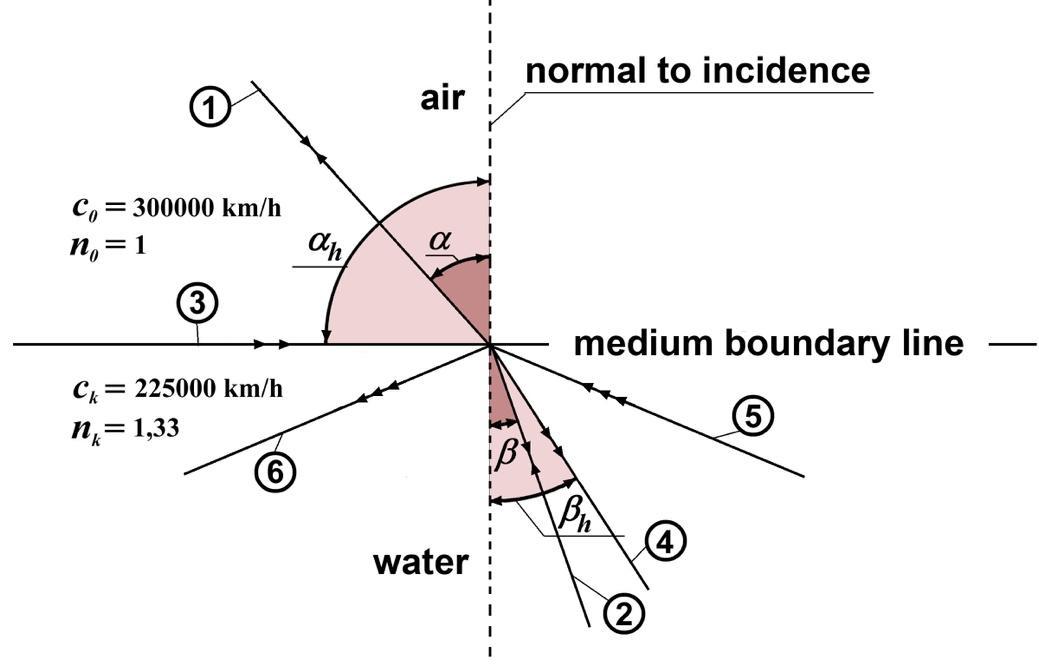
The incident light ray reaches the boundary of the medium at an angle measured from the perpendicular to the incident plane, where it is refracted, and continues its path at an angle (light ray) . If light enters a rarer medium into a denser medium, the inequality < is true, the angle of refraction will always be smaller than the angle of incidence. With a reversed beam direction, the phenomenon occurs in reverse.
Therefractiveindexoftwomediarelativeto each otheralso determines the anglesofrefraction:
So if in medium (in our case in air) the light reaches the interface at an angle , and in medium (in our case water) it travels at an angle
2.4.2. Reflection of light, transmission of light
The angle of incidence can be increased up to a maximum of 90 ° ( is the limiting angle of
incidence), then the angle of refraction increases to the limiting angle h (see ray ), and based on the law sin 90°= 1, the following relationship can be written:
Then the outgoing light ray "rubs" the surface of the medium. By further increasing the angle of , the light can no longer exit the medium, but in this case it undergoes total reflection at the interface (). Fiber optics exploit this law of nature to trap light, which LED technology uses for decorative purposes at most, but in panels, driven by LED light strips, total internal reflection is the basic principle of operation of lighting panels, supplemented by the fact that the phenomenon of diffusion in the panel material is also used. (LCD displays, monitor panels, etc.)
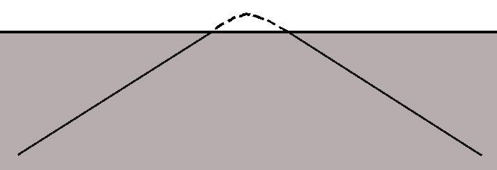
Amore accurate physical explanation of total internal reflection is that light actually penetrates the boundary medium at a small depth (one or two wavelengths away), otherwise it would be a contradiction that total internal reflection depends on the refractive index of the medium into which the light does not even enter. During surface penetration, it gradually returns to the starting medium, whilethereflectedrayis slightlyshiftedbecauseit also travels ashortdistance in it (Goos-Hänchen phenomenon). The conditions are shown in Figure 2-9.
2.4.3. Reflection, transmission
Mediums can both reflect and transmit radiation. This is measured by the reflection coefficient and the transmission coefficient. The reflection coefficient is the ratio of the incident and the back-radiated powers:
and the transmission coefficient:
Thereflection and transmission coefficients dependonthewavelengthof thelight andthe angle of incidence and reflection, i.e. ρ=ρ( , , ) or τ=τ( , , ).
The total reflection and transmission coefficients indicate that the incident light ray is completely reflected or transmitted through the material.
2.4.4. Fresnel reflection
Aspecial case when the angle of incidence is zero, i.e. the light is incident perpendicular to the mediumboundaryandis partiallyreflectedfromit.Itwasexperimentally foundthatthefraction of the total energy reflected depends on the refractive index n of the material, which is called Fresnel reflection after its inventor. The relationships are shown in Figure 2-10.
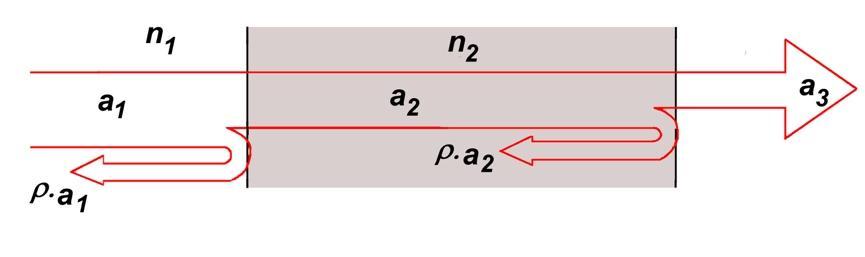
A light ray with amplitude a1 arriving from a medium with refractive index n1 travels at a medium boundary with refractive index n2 with amplitude a2 reduced by reflection factor ρ, and then, upon exiting the medium, is reflected again with amplitude ρ·a2, and the resulting exit amplitude is
and the reflection factor depends on the difference in refractive indices on both sides of the boundary. Its value is given by the following expression:
2.4.5. Light scattering (indicatrix)
According to the above equation, ρ is negative if the wave travels from a medium with a lower refractive index to a medium with a higher refractive index. The negative sign means a 180° phase shift for the reflected wave.
In reality, this also happens with a large part of theso-called regular light beam, but a small part, the so-called diffuse light beam, is scattered on the surface.Thus, the factors are also composed of two components:
The ratio of the two components is determined by the scattering indicatrix. Figures 2-11 show the scattering mechanism for the reflective and transparent cases.
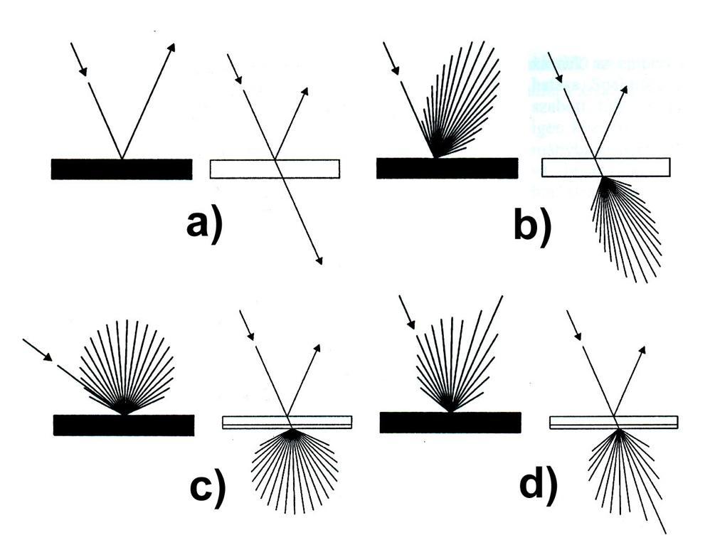
Figure 2-11. Scattering indicatrix in the case of reflection and transmission a) directed, b) directed scattered, c) scattered, d) mixed
2.4.6. Reflection, transmission, opacity, density
The scattering of light cannot be explained by geometric optics, its operation is described by wave optics. The same applies to the event occurring at the boundary of two media. The reflection coefficients ofsomenon-transparent materials andpaintedsurfaces aregiveninTable 2-2.
Table 2-2. Reflectance coefficient of opaque materials
Inthe case oflight-transmitting materials, wedistinguish betweentransparent, semi-transparent and diffuse materials. The characteristic of a transparent material is that most of the light passes without changing direction and only a small part is scattered. A semi-transparent material (frosted glass sheet) transmits light to a large extent, but the scattering is significant. Diffuse materials (e.g. milk glass) are characterized by the fact that the light is scattered, the original light direction does not dominate.
In the case of transparent materials, the reflection and transmission coefficients are also important. The data of some materials are contained in Table 2-3.
Table 2-3. Reflection and transmission coefficients of transparent materials
There are also materials that are semi-transparent-semi-reflective, for which both phenomena exist in some proportion. These also have many applications in LED lighting technology.
We utilize reflection when designing reflective surfaces, and the transmission factor can be important when designing prismatic surfaces, where we want to increase the narrow beam of an LED even in the entire spherical range.
In practice, we calculate the light transmission or light reflection ability of a material, as a percentage. Thus, for light transmission, the transmission factor is:
and for reflection, the reflection factor is:
where T and R are dimensionless ratios, with values between 0 and 1. It is also customary to calculate their reciprocals, the opacity O, or with its logarithm, the density D:
Some values are summarized in Table 2-4:
Table 2-4. Opacity and density as a function of light transmission and reflection
2.4.7.
Retroreflection can be considered a special case of reflection, which takes on a new meaning in LED lighting technology.Areflective surface is often needed that reflects the incident light rays mainly in the direction of incidence. For example, if we integrate small light-transmitting spheres or prisms into the reflective surface, the incident light rays are reflected in parallel. This is the principle of the “bead screen” used for projection, but it is also excellent for scattering the light of the LED light source (reducing glare). The phenomenon is shown in Figure 2-12.
Based on the definitions, we summarize the known laws of radiation that are utilized by LED lighting technology. The laws of radiation propagation are of course also true in photometry, so the radiated power is equivalent to the corresponding luminous flux.
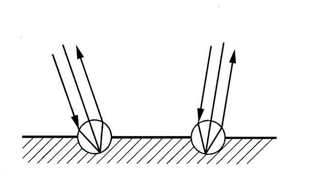
Figure 2-12. Retroreflection with embedded spheres
2.4.8. Planck's radiation law
Planck's radiation law is mainly used in thermal radiation (see Chapter 12). Thermal radiation is the longest wavelength range of electromagnetic radiation. In addition to the radiation of thermal energy, there is a significant amount of thermal energy lost during energy transformations, which must be radiated to the surrounding space. The specific power radiated by an absolutely black body depends on both temperature and wavelength. This is described by the following relationship for the spectral radiation density:
where c1=2·π·h·c2=3.742·10–6 W·m2 is Planck's first radiation constant, and c2=h·c/k=1.439·10–2 m·K is Planck's second radiation constant.Thespectral radiation is shown in the diagram in Figure 2-13, parameterized by temperature, as a function of wavelength.
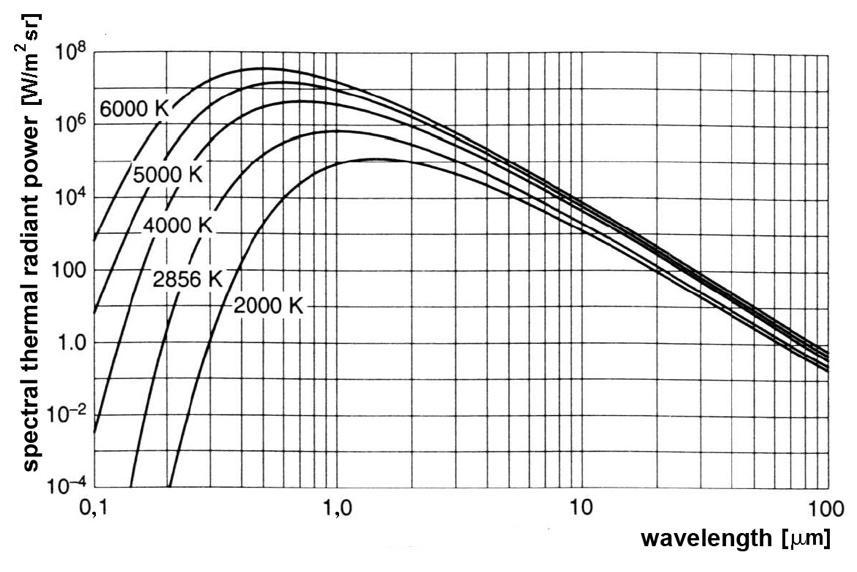
Figure 2-13. Thermal radiation as a function of wavelength
2.4.9. Wien's radiation law
Inpractice, �� ��2 ���� ≫1,whichleads toasimplificationofequation(2-18).Thisis Wien's radiation law:
The specific radiated power (Mλ) of an absolutely black body as a function of wavelength, parameterized by temperature, is given by the characteristic diagram, which we saw earlier in Figure 1-4.
An absolutely black body or absolutely black radiator is an ideal body that absorbs all radiation incident on it, i.e. does not show wavelength selectivity. = 1, so its emissivity is unity, and the spectral distribution of its emitted thermal radiation is described by Planck's law. It is of greater importance for thermal radiators (incandescent lamps), in the book this law is used more for heating elements and. heat radiation of heat sinks.
2.4.10. Wien's shift law
Wien's shift law gives a relationship between the wavelength corresponding to the maximum of the radiation of a black body and the temperature:
where bs =2.898·10–3 m·K, Wien's constant. From this it can be seen that with increasing temperature the wavelength corresponding to the maximum emitted radiation density shifts in a decreasing direction, i.e. towards higher frequencies. In practice, it confirms the empirical fact that the more heated the material, the whiter it shines, i.e. towards the blue.
2.4.11. Stefan-Boltzmann radiation law
The Stefan-Boltzmann radiation law gives the radiation power per unit area of a black body summed over all wavelengths:
4 (2-21) where s=5.67·10–8 W·m–2·K–4 is the Stefan-Boltzmann constant
2.4.12. Radiometric fundamental law
If we consider the relationship between a radiating and an irradiated surface, then the radiometric fundamental law is the authoritative one, which gives the radiation power ΔΔPs that a body radiating on a surface dAs with a radiation density Φs under a radiation angle βs from
another, radiates at an angle of incidence βe onto a surface element of size dAe at a distance r. The surface normals are denoted by dAs·coss and dAe·cose:
2.4.13. Square distance law
The square distance law appliestotheentireradiationspectrum.Weexaminehowtheluminous flux of a point light source marked Q, or surface A1, changes with increasing distance. An explanation is provided in Figure 2-14.
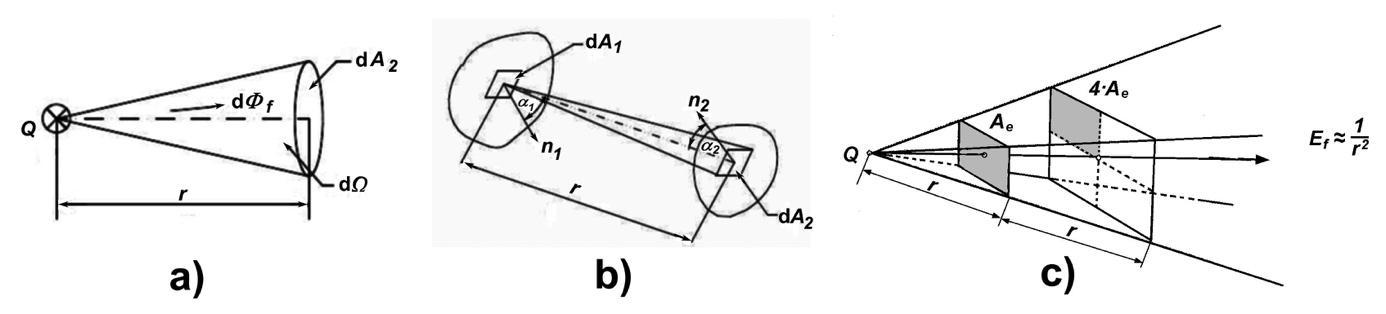
Figure 2-14. Illustrating the square distance law
In figure a) the luminous flux d f in differential size illuminates the part dA2 of the surface A2 at a solid angle d: by definition
and the illumination of the surface d
i.e. it is apparently inversely proportional to the square of the distance.
In the general case, the luminous flux makes an angle 1 with the normal of the illuminating surface A1, and the illuminated surface A2 makes an angle 2 with the light beam, so in general form, according to Figure b), the distance law is:
and in Figure c), we can state for the radiated power that the radiated specific power perceived by a surface Ae is inversely proportional to the square of the distance r between the emitter and the surface Ae:
2.4.14. Lambert's law
For a light source whose surface element has a luminous intensity or radiant intensity that is
independent of direction, and the intensity of the radiation is examined at an angle βs from the perpendicular (normal) direction, Lambert's law applies:
where I0 denotes the radiant intensity in the direction βs=0°. If the radiant intensity Φs is independent of the direction of observation, we speak of a Lambert radiator or a Lambert diffuser. The relationships are explained in Figure 2-15.
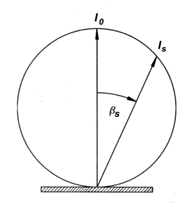
Figure 2-15. The Lambert radiator
The law is not only valid for active light sources, it is also used for isotropic surfaces with a unit transmission or reflection coefficient.
2.4.15. Kirchhoff's radiation law
The ratio of the radiated specific power to the absorption coefficient is constant, independent of the properties of the body, depends only on the wavelength and temperature, and its magnitude is equal to the specific power radiated by a black body. This is stated by Kirchhoff's radiation law:
This means that at a fixed wavelength a body radiates more strongly, the more strongly it absorbs. This is used, for example, in heat sinks, because when painted black, it radiates heat better than when painted white or metallic (αs=εs).
Radiating surfaces can be classified based on their emissivity εs, which is used in refrigeration technology. According to this, we distinguish between black, gray and selective radiators. In Fig. 2-16., we can see the wavelength dependence of the emissivity and spectral specific power of the three radiator categories. For gray radiators, is wavelength-independent, while for black radiators, it is 1.
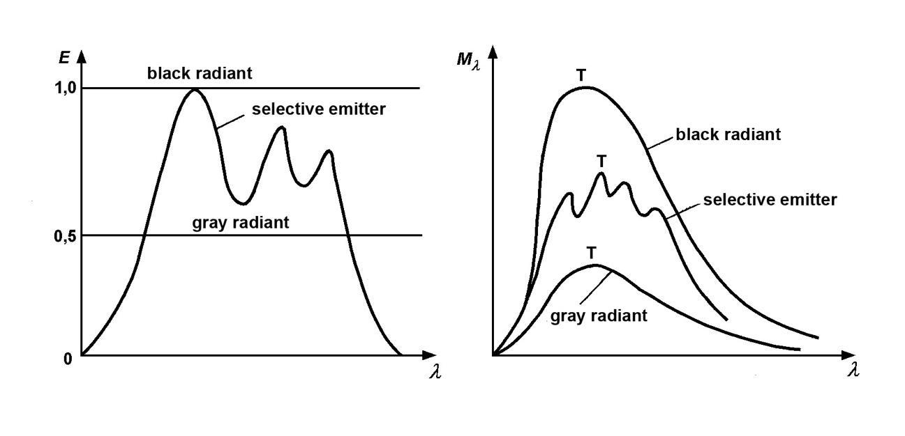
Figure 2-16. Emissivity and spectral specific power as a function of wavelength
The range of values of the emissivity of the three radiator categories is given in Table 2-5
Table 2-5. Emissivity factors of a radiator radiant body emission factor
2.5.1. Wavelength, colors
The visible light range falls within the wavelength range of 300…800 nm. Colors can be assigned to each wavelength, which our eyes can distinguish – due to a special physiological effect (see Chapter 3.3).
The concept of color can be defined according to several aspects:
• perception – psychological phenomenon
• stimulus – psychophysical phenomenon
• characteristic of optical radiation – physics
• characteristic of light – one of the dimensions of color description
In LED lighting technology, the concept of color is mainly understood as optical radiation – to meet measurement needs, but due to visual perception, the psychological and psychophysical approach is also important, andwhenevaluatingartisticworks, color dynamics, colorsaturation, pastel colors, etc. provide the aspects.
The light transmission and reflection of the surface of bodies are wavelength-dependent, so the εsfactordetermined foramaterial,e.g.only applies tolightingwithaspecificcolortemperature. This is also used the other way around, the light-reflecting or light-transmitting effect of a colored surface also affects the spectral composition of the ambient lighting (e.g., a red carpet lends a warm light to the room). The surfaces of bodies can therefore be classified into two large groups: the group of non-colored and colored surfaces (of course, the transition is continuous in terms ofcolorsaturation).Colorless surfaces reflect andtransmit lightto thesame extent at all wavelengths, while colored surfaces do so depending on the wavelength (color). The relationships are illustrated in Figure 2-17.
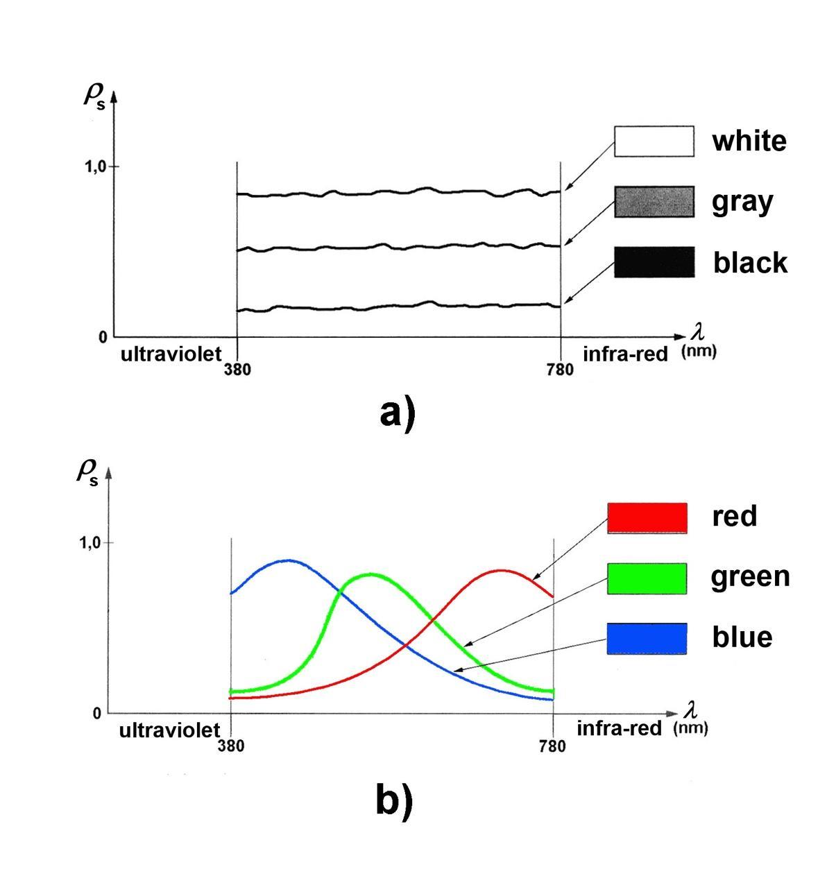
Figure 2-17. Reflection factor: a) for colorless surfaces, b) for colored surfaces
According to the law, the color of a surface illuminated by light of a given composition is influenced by the reflection and transmission factors. Figure 2-18. we can see the color distribution of a transreflective surface for wavelength-dependent reflection and transmission factors βs(λ) and τs(λ):
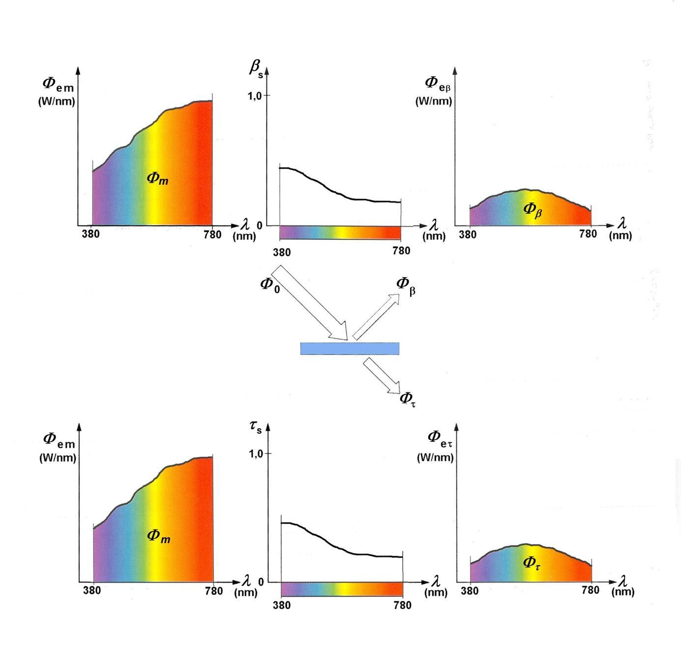
Figure 2-18. The color of the surface of a transreflective body is wavelength-dependent (source: [154])
The same can be said for the color of the surface of bodies, which is influenced by the spectral composition of the illuminating light. The relationships are shown in Figure 2-19.
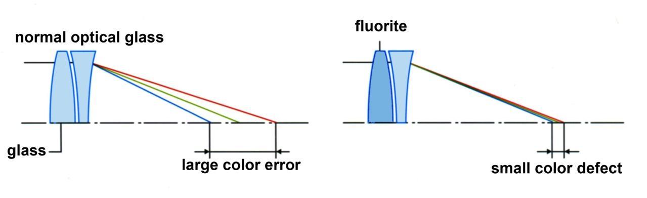
In practical lighting technology, the color of objects is more likely to be reflected, but light transmission is also important, which is also wavelength-dependent. Different types of glass and plasticswith goodoptical properties arealso used in lightingequipment. Using theexample of a Canon telephoto lens, we will show that chromatic aberration can occur during light transmission due to the wavelength-dependent refraction of the lens glass material. (see Figure 2-20 )
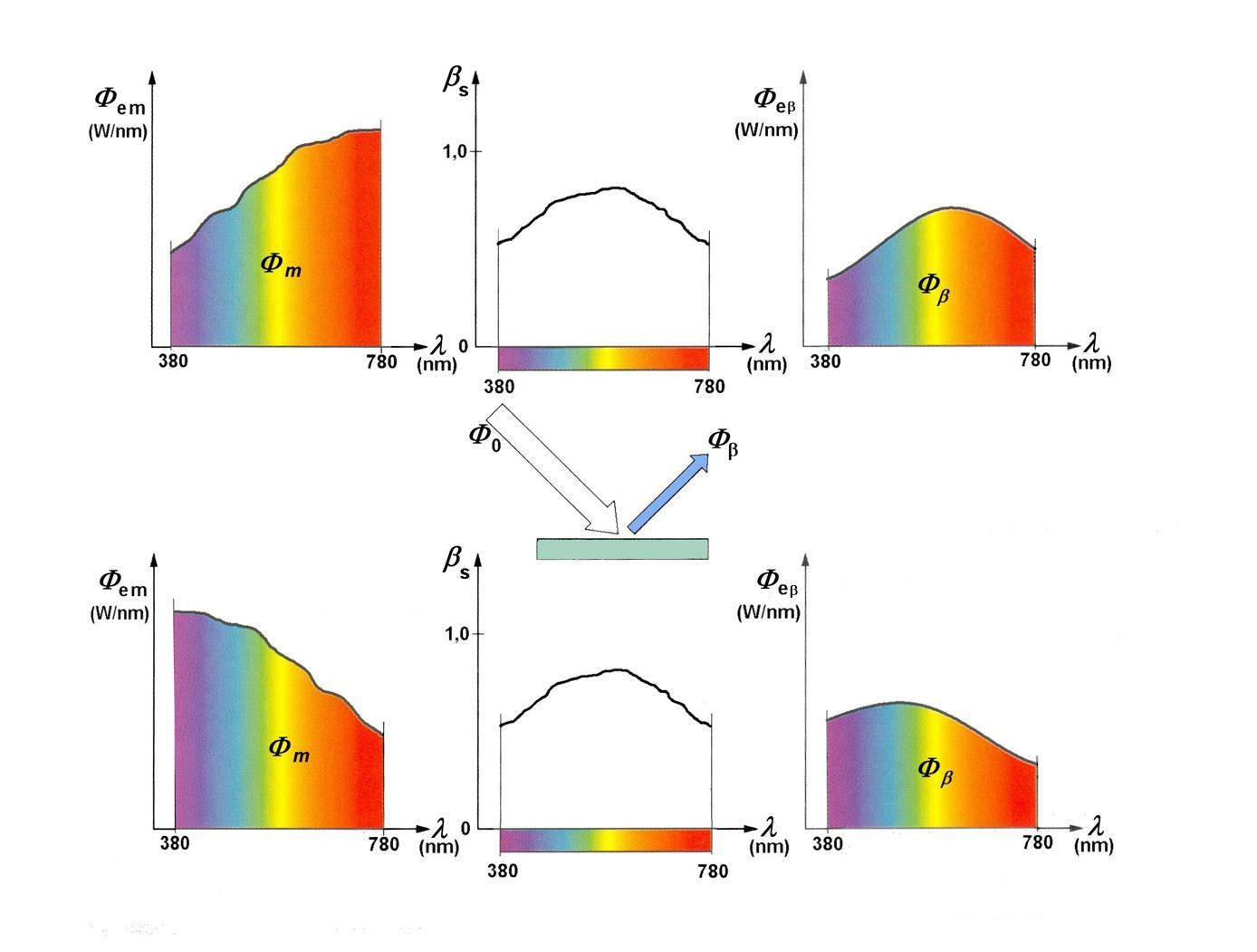
Figure 2-19. The dependence of the color of the surface on the illuminating light (source: [154])
That is why the lens is usually composed of several elements, so that the convex and concave lens aberrations compensate for each other, but in the presented solution, a change in material brings reliable results, and the use of fluorite gives excellent results. Of course, the spectrum of the light source is fundamental, the fluorite lens was developed for sunlight, the illumination chromatic aberration of an LED light source can be successfully corrected with a different material or by the design of the lens. This is desirable, for example, in floodlight technology.
These relationships are of great importance in LED lighting technology, because the spectral componentsofthelightsourcecandistortthecolorofobjects.Colormeasurementisnotsimple, because the “scientifically determined” color, i.e. the spectral distribution of wavelength and colorcontent,does not provideaclearvisual experience,sinceour colorvisionis not linearand, moreover, is slightly different for each person. During the development of science, man's endeavor has been to categorize colors in some way. The human eye is not suitable for absolute color determination, but for determining relative differences. It is therefore advisable to set up a collection of color samples and compare everything to it. Several such collections have been created, perhaps the most famous (and most authoritative) is the Pantone color scale, developed mainlyforprintingapplications.Butforthis,weexaminevisibilityandcolormixingprocedures, based on the literature. Here we undertake to briefly introduce only a few concepts.
Physics perceives light as electromagnetic radiation, which has a wavelength and energy (λ and Φf). During vision, we use the concept of luminous flux for the radiation power that appears in our consciousness, the unit of which is lumen (lm).
According to the teachings of physics, luminous flux is the integral of the part of the physical radiation power corrected by the visibility function with respect to wavelength:
where Km is aconstant, its valueis 680lm/W, whichalso means thatlight produced with electric current has a maximum, theoretically 100% efficiency of 680 lumens per watt. In practice, for LEDs, an efficiency of 100…120 lm/W is common, which is now 150…300 lm/W efficiency has achieved, there is still plenty of room for further research and development.
Thecolorsensitivity ofourvisionisdeterminedbythreetypesofcones ontheretina,red,green, and blue (in English, Red, Green, and Blue, i.e. R, G, and B). Our color vision is based on the so-called trichromatic color system. These primary colors, as monochromatic colors, do not occur in practice, but any color can be mixed from the three primary colors – according to Grassmann's law – according to the ratio of the components. This is also called the additive method, because the mixed color is created by adding the color components, although only the color stimuli themselves are important for the result, not their spectral composition, and the law also states that the color of the mixture also changes during the continuous change of the intensity of any color stimulus. If all three components are present in the correct ratio, we get the color white. The relationships are shown in Figure 2-21 b).
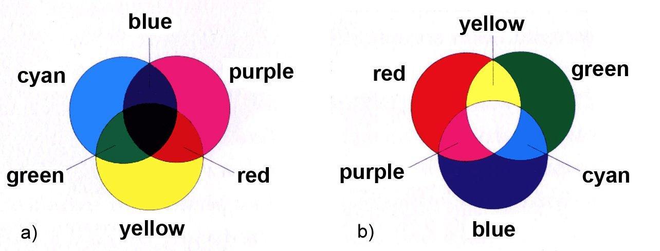
If we do not work with colored lights, but evaluate with lights reflected from the surface of bodies, then we can do this with color filtering, for which the subtractive (i.e. subtractive)
method is best recommended. The basic colors of the subtractive method are magenta, cyan, and yellow. The two methods are compatible with each other, through their mixed colors. Color perception is defined by color models. Our eyes are not equally sensitive to colors.
Colorvisionisbasedonthecombinationofrelativestimulusdifferences,so lightswithdifferent spectral energy distributions result in the same color stimulus. This is metamerism. Metameric colors are colors that appear to be the same, but their spectral energy composition is different. The identity applies to several colors. A complete atlas of visible colors can be compiled from similar (metamer) colors. In this atlas, most of the colors can be produced by mixing three independent (immiscible) monochrome colors and can be cataloged based on the ratio of the three colors. According to our current knowledge, the three colors, called primary colors, are the 700 nm red (R), 546.1 nm yellow (Y), and 435.8 nm blue (B), which cause the strongest color stimulus. However, since the spectral sensitivity distribution of the three color-sensing cones overlaps, there are no three representative wavelengths whose mixtures can determine all color shades. A mixture of two colors always results in a less saturated color, and the added third primary color also increases the white content.
Four laws apply to this trichromatic color production: symmetry, transitivity, proportionality, and additivity. These are used by color designers and color aesthetes in shaping our everyday products and visual experience. The laws are discussed in detail in the literature.
2.5.3. Color systems, color spaces
Color vision is a concept related to humans. Just as no two people are the same, color vision is also subjective, each color is associated with a wavelength range, with no fixed boundaries. Apart from color blind or colorblind people, people with healthy eyes would also mix colors in different proportions, e.g. to display the green of a leaf. What we call a hue is actually a slight shift in the wavelength range. However, humans have always strived to accurately measure and define colors. There have been many attempts to do this throughout history.
Color can be represented by its three components, and by analogy with the three spatial dimensions, we speak of a color space, which is a spatial representation of a virtual threedimensional multitude of color stimuli. A color therefore represents a single point in a virtual spatial coordinate system. If only the color information is interesting, then we speak of a gamut, and it can also be represented two-dimensionally, on a plane, if the intensity of the light also matters, then a spatial representation is necessary. Throughout history, with the development of science, several color space theories have been born.
The spectrum of light can therefore be linked to the cognitive content of the color stimulus in three dimensions, these are hue, saturation and brightness (otherwise: luminance). What do these concepts mean, and how are they used in LED lighting technology?
absorption, 16 brightness, 48 circadian effect, 101 color rendering, 59 color temperature, 24
DALI, 277 diffraction, 25
DMX system, 377 electrical pumping, 661 Electroluminescence, 26 electromagnetic radiation, 12 FED, 577 fluorescence, 28 glare, 94 heat pipe, 190 hue, 48 infrared heaters, 826 interference, 16 KNX, 367
LCD, 578
LiFi communication, 539 light reflection, 38 luminous intensity, 50 microLED, 586 OLED, 585
optical pumping, 664 PDP, 575 PFC, 286 phosphorescence, 23 photoluminescence, 28 photometric, 24 photosynthesis, 409 photovoltaic effect, 793 PIR, 384 PIR sensor, 384 plasma laser, 674 polarization, 25 power factor correction, 286 radiant density, 24 radiated energy, 25 Radiated energy, 295 radiometric, 40 reflection, 12 refraction, 32 saturation, 48 solid angle, 24 TIM, 189 transmission, 32 VFD, 574
Light shapes our world—from the glow of a simple LED to the precision of a laser beam and the immense power of the sun. LEDs, Lasers, and Sunlight – Principles, Design, and Real-World Applications of Modern Photonics is your comprehensive guide to understanding, designing, and applying modern light technologies.
This book takes you on a journey from the fundamentals of photonics— covering the nature of light, optical laws, and color theory—to real-world engineering with today’s most important light sources. You’ll explore how LEDs work, how to design efficient lighting systems, and how to tackle practical challenges such as thermal management, power supply design, and optical performance.
Beyond illumination, the book opens doors to specialized applications: horticultural lighting for plant growth, infrared and ultraviolet technologies, modern display systems from LCD to MicroLED, and the fascinating world of lasers—from their physics to their use in medicine, industry, and communication. It also connects light engineering to sustainability through solar energy and thermal radiation.
Written with a strong practical focus, this book bridges theory and application. Whether you are an engineer, student, or advanced hobbyist, you’ll gain the tools to turn concepts into working solutions—from selecting components to building complete systems.
If you want to understand light not just as a phenomenon, but as a powerful engineering tool, this book will illuminate the way.
Miklós Lambert was born in Budapest, Hungary, in 1940. He earned a Master’s degree in electronics engineering from the Budapest University of Technology, later specializing in digital engineering. He spent 23 years at the Ganz Danubius Shipyard designing automation systems for ships and cranes, securing seven patents. After 1989, he turned to technical publishing, authoring over 17 books on electronics, some of which have been translated into German. He served for 23 years as editor-in-chief of Elektronet, founded the National Electronics Society of Hungary, and remains active as an author focusing on semiconductor emitters and sensor technologies.
Elektor International Media www.elektor.com