Elektor Magazine is published 8 times a year by Elektor International Media b.v. PO Box 11, 6114 ZG Susteren, The Netherlands Phone: +31 46 4389444 www.elektor.com | www.elektormagazine.com
Content Director: C. J. Abate
Editor-in-Chief: Jens Nickel
For all your questions service@elektor.com
Subscription rates: As of December 1, 2025, the print membership (Gold) is €144.95 per year for a one-year subscription. And the digital membership (Green) is €99.95 for a one-year subscription and €169.95 for a two-year subscription.
Become a Member www.elektormagazine.com/membership
The circuits described in this magazine are for domestic and educational use only. All drawings, photographs, printed circuit board layouts, programmed integrated circuits, digital data carriers, and article texts published in our books and magazines (other than third-party advertisements) are copyright Elektor International Media b.v. and may not be reproduced or transmitted in any form or by any means, including photocopying, scanning and recording, in whole or in part without prior written permission from the Publisher. Such written permission must also be obtained before any part of this publication is stored in a retrieval system of any nature. Patent protection may exist in respect of circuits, devices, components etc. described in this magazine. The Publisher does not accept responsibility for failing to identify such patent(s) or other protection. The Publisher disclaims any responsibility for the safe and proper function of reader-assembled projects based upon or from schematics, descriptions or information published in or in relation with Elektor magazine. For our full terms and conditions, please refer to our website.
Print
Senefelder Misset, Mercuriusstraat 35, 7006 RK Doetinchem, The Netherlands
Jens Nickel
International Editor-in-Chief, Elektor Magazine
A Good Idea
Sixty-five years ago, Dutch electronics enthusiast Bob van der Horst had an idea: instead of acquiring knowledge from dry textbooks and datasheets, electronics engineers could explore new fields of knowledge through hands-on projects that are enjoyable to build and genuinely useful in the end.
He set up his first magazine editorial office in his home, and because he also wanted to support the community with printed circuit boards, prototypes were diligently etched in the bathroom. The rest is history: The founder of Elektor soon recognized the potential of the large German market, and later English and French editions were added.
If you are interested in the history of our magazine and electronics in general, we highly recommend our 60th-anniversary special. In it, we explored each decade and reported on the most important electronics developments
of the era, as well as legendary projects — for example, a DIY oscilloscope that helped users save a considerable amount of money (www.elektormagazine.com/60years).
Of course, we also want to celebrate our 65th anniversary in style (page 12)!
We remain faithful to our founder’s great idea in this issue as well: my colleague, Saad, has developed a board that allows you to experiment with various wireless technologies while learning a great deal in the process (page 6); a surprising Wi-Fi-based application can be found on page 16. And our external authors have once again contributed a wide range of exciting projects! <
BU ZZZ Around
The growth of the Elektor TV YouTube channel tells me one thing: technical curiosity is alive and well. The secret behind 126,000 subscribers isn’t production tricks or algorithm hacks. It’s consistently publishing content that makes engineers think, learn, and occasionally say, “I need to try that!”
C. J. Abate — Chief of Content & Communications
Excited for electronica Fast Forward and looking forward to connecting with innovative startups. If you would like to join us, please don’t hesitate to reach out!
Morgan de Saint Jorre — Sales Manager
The Team
International Editor-in-Chief: Jens Nickel | Content Director: C. J. Abate | International Editorial Staff: Hans Adams, Asma Adhimi, Roberto Armani, Eric Bogers, Rolf Gerstendorf (RG), Ton Giesberts, Saad Imtiaz, Alina Neacsu, Dr. Thomas Scherer, Jörg Starkmuth, Clemens Valens, Brian Tristam Williams | Regular Contributors: David Ashton, Stuart Cording, Tam Hanna, Ilse Joostens, Prof. Dr. Martin Ossmann, Alfred Rosenkränzer | Graphic Design & Prepress: Harmen Heida, Sylvia Sopamena, Patrick Wielders | Publisher: Erik Jansen | Technical Questions: editor@elektor.com
Elektor at
Disrupting Electronics Since 1961
6 MultiRF Dev Board
A Platform for Evaluating Short- and Long-Range Wireless Protocols
16 Wi-Fi-Based Person Detection on an ESP32 When Your Router Becomes a Motion Sensor
24 Wireless Scales Four Small Scales = One Big Scale
46 Ecologging
A Modular Environmental IoT Station for Field Research
72 Redox Meter Monitor Water Quality with an ESP32
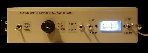
79 Instrumentation Amplifier For Physics and Engineering Experiments
86 Active Differential Audio Filters For Professional Crossovers and More
96 Telegram-Controlled Water Heater Interface Module A Solution Based on an ESP32 and Arduino Software
110 Alarm Signal Injector Plus Power Tools for Finding Broken Wires
Instrumentation Amplifier For Physics and Engineering Experiments
Walter, the Compact IoT Module
44 electronica Fast Forward 2026 Inviting Startups and Industry Partners
54 Wireless Connectivity in Medical Applications Always on the Pulse with Bluetooth LE
64 Increasing Agricultural Efficiency With AI Modeling and Sensors
BONUS CONTENT
Check out the free IoT & Sensors bonus edition of Elektor Mag!
> Modern Sensors
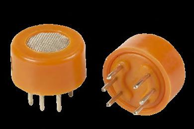
> Peculiar Parts: Gas and VOC Sensors
> Secure Communication with RSA and AES
> Infographics: IoT & Sensors
Next Edition
Elektor Magazine Circuit Special 2026
In the tradition of our Summer Circuits, the next edition will be filled with dozens of DIY projects, retro circuits, tips and tricks, and much more! Circuit Special 2026 will be published around August 12, 2026
Elektor Magazine September & October 2026
As usual, we’ll have an exciting mix of projects, circuits, fundamentals, and tips and tricks for electronics engineers and makers. Our focus will be Wireless & Communication.
> ESP32 Rocket Drone
> Compact Audio DSP
> Internet Radio to AM Converter
> Designing Space Electronics
> AM Transmitter
> Teaching a Robot Arm to See and Move
Elektor Magazine’s September & October 2026 edition will be published around September 9, 2026. Arrival of printed copies for Elektor Gold members is dependent on shipping times.
ektorlab • Elektorlab
MultiRF Dev Board
A Platform for Evaluating Short- and Long-Range Wireless Protocols
By Saad Imtiaz (Elektor)
This article presents a development board designed for prototyping, development and research of different wireless technologies. It integrates six RF communication options: Wi-Fi, ESP-NOW, BLE, LoRa, and two proprietary protocols in the 2.4-GHz and 433MHz ranges. To make the board even more versatile, a GPS module, an SD card socket and expansion connectors for sensors and the like were integrated, too.
When working with wireless systems, most design decisions are made long before the final product exists. Range, reliability, latency, and coexistence with other radios are often estimated from datasheets or reference designs. In practice, these parameters depend heavily on layout, antennas, firmware timing, and real-world environments.
The motivation behind this project was twofold. First, I needed a dedicated LoRa testing platform to evaluate range and packet
reliability under different conditions. Second, I wanted a single development board that could host and compare multiple wireless protocols side by side, without constantly swapping modules or redesigning hardware. Commercial RF test tools exist, but they are either protocol-specific or too abstracted for hands-on firmware experimentation.
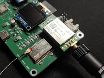
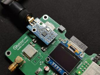
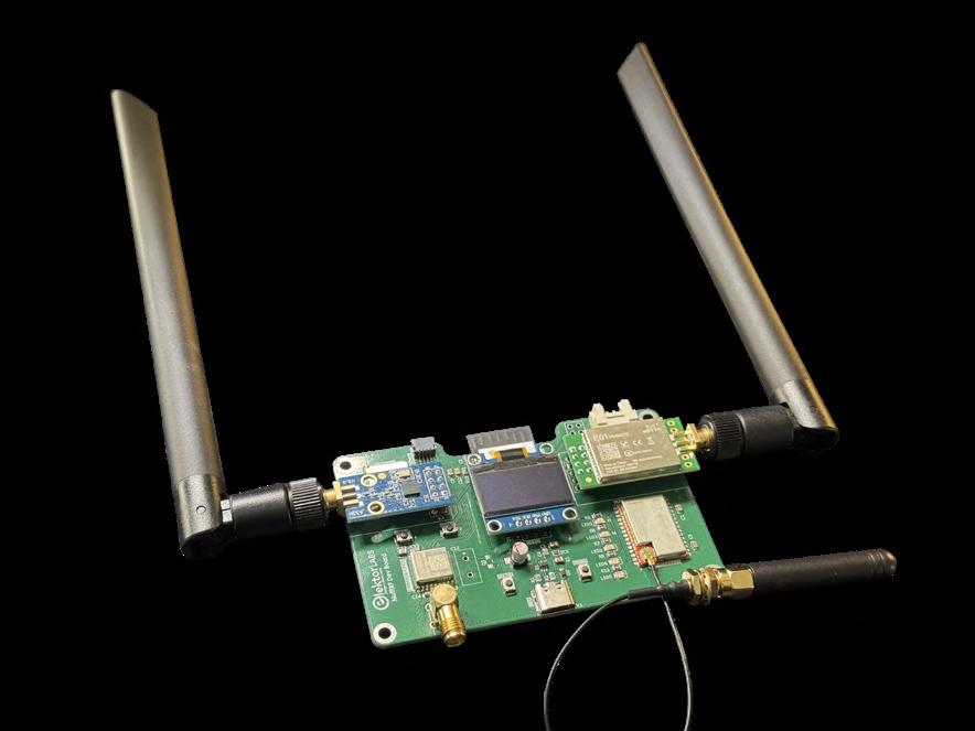
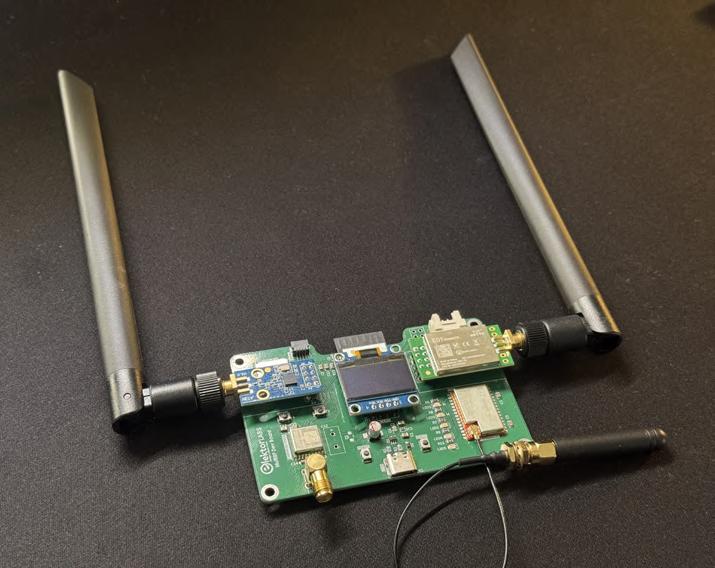
The result is the MultiRF Dev Board (Figure 1): a stacked wireless development platform intended for engineers and makers who want
to test communication links, compare protocols, and prototype wireless systems quickly. By integrating multiple radio technologies on a single controlled hardware platform, it becomes much easier to evaluate trade-offs such as range versus data rate, latency versus power consumption, and robustness versus complexity, without constantly redesigning the hardware.
System Architecture
The system architecture of the MultiRF Dev Board is centered around an ESP32S3-WROOM-1 module from Espressif. The integrated ESP32-S3 dual-core processor acts as the main controller and communication hub, as shown in the block diagram (Figure 2). Whereas Wi-Fi, ESP-NOW, and BLE are handled by the WROOM module itself, LoRa and two proprietary 2.4 GHz and 433 MHz protocols are made available by external transceiver modules.
All wireless modules and the other peripherals are connected directly to the ESP32
Figure 1: The MultiRF Dev Board.
Figure 2: The block diagram.
Wireless Technologies Integrated
The board integrates six wireless technologies in total: Wi-Fi, Bluetooth LE, ESP-NOW (via ESP32-S3), LoRa (868 MHz), nRF24L01P (2.4 GHz), and CC1101 (sub-GHz FSK/ OOK). Each serves a different engineering purpose.
> Wi-Fi offers high data throughput and direct IP connectivity, making it ideal for gateways and data logging. The trade-off is higher power consumption and shorter practical range compared to sub-GHz systems.
> Bluetooth LE (BLE) is optimized for low power and mobile device integration. It is well suited for configuration, provisioning, and short-range telemetry, but it is not intended for long-distance communication.
> ESP-NOW provides low-latency peer-to-peer communication between ESP devices without requiring a router. It is efficient and simple, but limited to Espressif ecosystems.
> LoRa (868 MHz) enables long-range communication with very low data rates and strong link budgets. It is ideal for sensor networks and outdoor deployments, but not suitable for high-throughput applications.
> nRF24 (2.4 GHz) offers low-latency, short-range communication with moderate data rates and low power consumption. It is simple and efficient, but range is limited compared to sub-GHz systems.
> CC1101 (sub-GHz FSK/OOK) provides flexible modulation options and good range at moderate data rates. It is excellent for proprietary protocols and experimentation, but requires more configuration effort compared to higherlevel stacks like LoRaWAN.
Each of these technologies represents a different point in the wireless design space. Having them on one board allows direct comparison under identical hardware conditions.
For readers interested in a deeper technical discussion of wireless protocols, modulation schemes, range calculations, and link budgets, I recommend referring to my earlier background article on wireless communication technologies, where these protocols are talked about in detail [1].
using standard digital interfaces. The board is powered through USB Type-C, and the 5-V input is regulated down to 3.3 V using the Toshiba TCR15AG33 LDO [2]. Since all devices operate at 3.3 V, the entire system shares a single voltage domain, which simplifies design and eliminates the need for level shifting.
Two wireless modules are connected via UART: the E77-900M22S LoRa module [3] and the EWM108-GN05 GPS module [4] by Ebyte [5]. UART is suitable here because both devices operate naturally with continuous serial data streams. The GPS continuously outputs NMEA sentences to the ESP32, enabling real-time position logging and timing reference. The LoRa module, on the other hand, can be controlled and monitored through its serial interface, making configuration and debugging straightforward.
The 2.4-GHz nRF24L01P module (Ebyte E01-2G4M27D) [6] and the 433-MHz CC1101 module (Ebyte E07-M1101D) [7] are connected over a shared SPI bus. The E01-2G4M27D is based on the Nordic Semiconductor nRF24L01+ transceiver, a widely used low-power 2.4-GHz GFSK radio known for its low latency and simple packet-based communication model. The E07-M1101D integrates the Texas Instruments CC1101 transceiver, a highly configurable sub-GHz device supporting FSK, GFSK, and OOK modulation schemes.
Each device has its own chip-select line, allowing the ESP32-S3 to communicate with one radio at a time without bus conflicts. SPI is used here because these transceivers require higher-speed register access and payload transfer compared to UART-based devices. The microSD card is also connected via SPI,
enabling efficient data logging during range and performance testing.
An OLED display is connected over I²C for status monitoring, and push buttons provide simple user interaction. Overall, the architecture follows a clear and practical structure: the ESP32-S3 manages multiple radios using UART and SPI interfaces, logs data to SD, displays status locally, and can bridge everything over Wi-Fi. This modular approach keeps the system flexible while maintaining clean and understandable hardware organization.
Schematic Diagram
The brain of the MultiRF board is the ESP32S3-WROOM-1 (MOD2), which coordinates all communication, data logging, and user interaction, as shown in the schematic (Figure 3). The ESP32-S3 handles Wi-Fi, ESP-NOW and BLE internally, while externally managing the LoRa, nRF24, CC1101, GPS, OLED, and microSD interfaces. Its GPIOs are distributed to support SPI, UART, and I²C without signal conflicts, keeping the architecture clean and modular.
Power is derived from USB-C and regulated down to 3.3 V using IC1 (TCR15AG33) this regulator can supply up to 1.5 A with ultra-low dropout voltage and high ripple rejection (typ. 95 dB at 1 kHz). It also integrates overcurrent protection, thermal shutdown, under-voltage lockout, soft-start, and inrush current control. The recommended 4.7-µF input and output capacitors and 1.0-µF bias capacitor are implemented in the schematic, ensuring stable operation even during RF transmission bursts where current demand can increase rapidly. This is important because LoRa and sub-GHz transmissions can cause fast load transients.
The long-range radio is the E77-900M22S (MOD1) LoRa module, connected primarily over UART. It includes dedicated status LEDs for TX, RX, and JOIN, which provide real-time feedback during LoRaWAN association and packet transmission. These hardware indicators are very useful during testing, especially when evaluating network join success or link reliability without a serial monitor.
The 2.4-GHz short-range communication is handled by the nRF24L01P module
By C. J. Abate (Elektor)
From vacuum tubes to AI, from garage workbenches to cutting-edge labs, Elektor has spent 65 years at the heart of electronics innovation. Celebrate with us as we revisit the projects, people, and ideas that changed engineering.
In 1961, a new electronics magazine was launched in The Netherlands with a simple but ambitious mission: to help engineers, electronics enthusiasts, and students learn, build, and share technology. Sixty-five years later, Elektor has become much more than a magazine. It is a global platform for electronics engineering, a trusted
source of technical learning, and a thriving community of passionate people who love technology. This year, and well into 2027, we are proud to celebrate Elektor’s 65th anniversary.
Over the past six and a half decades, Elektor has documented — and often anticipated
— many of the most important developments in electronics. From analog circuits and radio experimentation to microprocessors, embedded systems, wireless connectivity, artificial intelligence, and the Internet of Things, we’ve been there every step of the way.
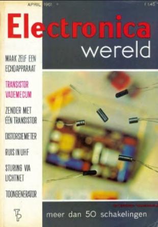
In 1961, Elektor featured a tone generator, a transistor guide, a distortion meter, and more.
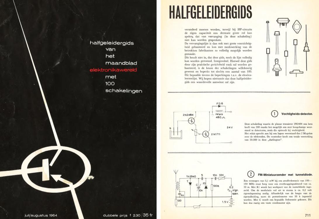
In 1964, Elektor debuted “Halfgeleidergids.” Today, we continue the tradition with Circuit Specials.
Technology has changed dramatically since 1961, but our mission remains remarkably consistent: to inspire people to create with technology and provide the practical knowledge needed to turn ideas into reality. Along the way, countless projects have been built on workbenches around the world using ideas first shared in Elektor. Countless engineers began their careers by building an Elektor project. Many entrepreneurs launched companies based on skills learned through our articles, books, and educational resources. And many lifelong friendships and professional relationships have been formed through our community.
Most importantly, none of this would have been possible without you. Whether you’ve been reading Elektor since the 1960s or discovered us through a recent video, livestream, social media post, or educational resource, you are part of the story. Our readers, members, authors, contributors, partners, and employees have collectively shaped what Elektor is today.
As we celebrate this milestone, we’re excited to look back on our history — and even more excited to look ahead.
Special Anniversary Content
Over the next year, we’ll be taking a deep dive into the rich history of Elektor and the people, projects, and ideas that helped shape it. Throughout our magazines, websites, newsletters, videos, and livestreams, we will
Back in 1961 ...
> Bob W. van der Horst launches Elektronica Wereld.
> First ICs move from lab prototypes to commercial adoption.
> Khrushchev and Kennedy meet at the Vienna Summit.
> Benfica defeats Barcelona in the European Cup.
> The Apartment wins the Best Picture.
> Average cost of a new car in the U.S.: $2,850.
> Dutch motorists pay ~0.65 Dutch guilders per liter of gas.
> Turin hosts the Italia ’61 Exposition.
> Rudolf Mössbauer of W. Germany wins the Nobel Prize in Physics.
> French filmmaker Jean-Luc Godard releases A Woman Is a Woman.
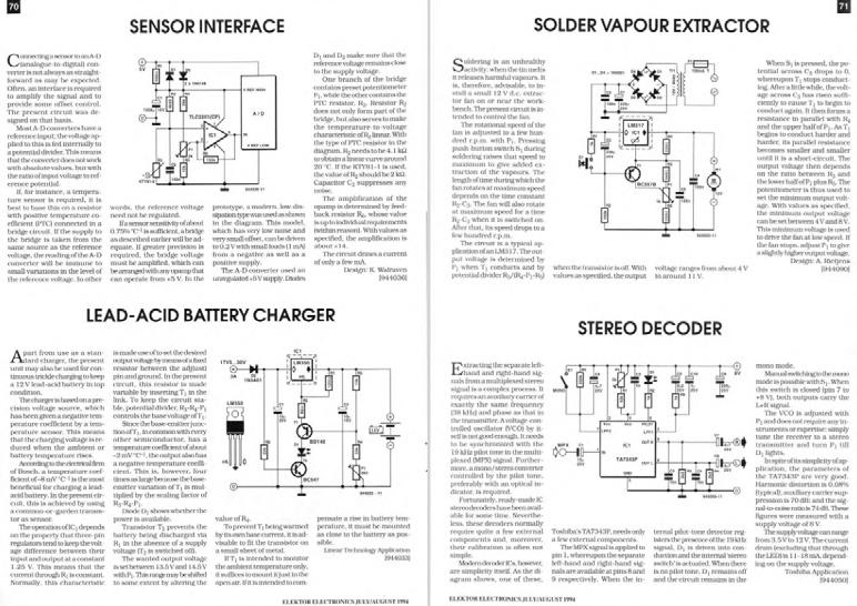
Here are interesting projects from July/August 1994: a sensor interface, a lead-acid battery charger, a solder vapor extractor, and a stereo decoder.
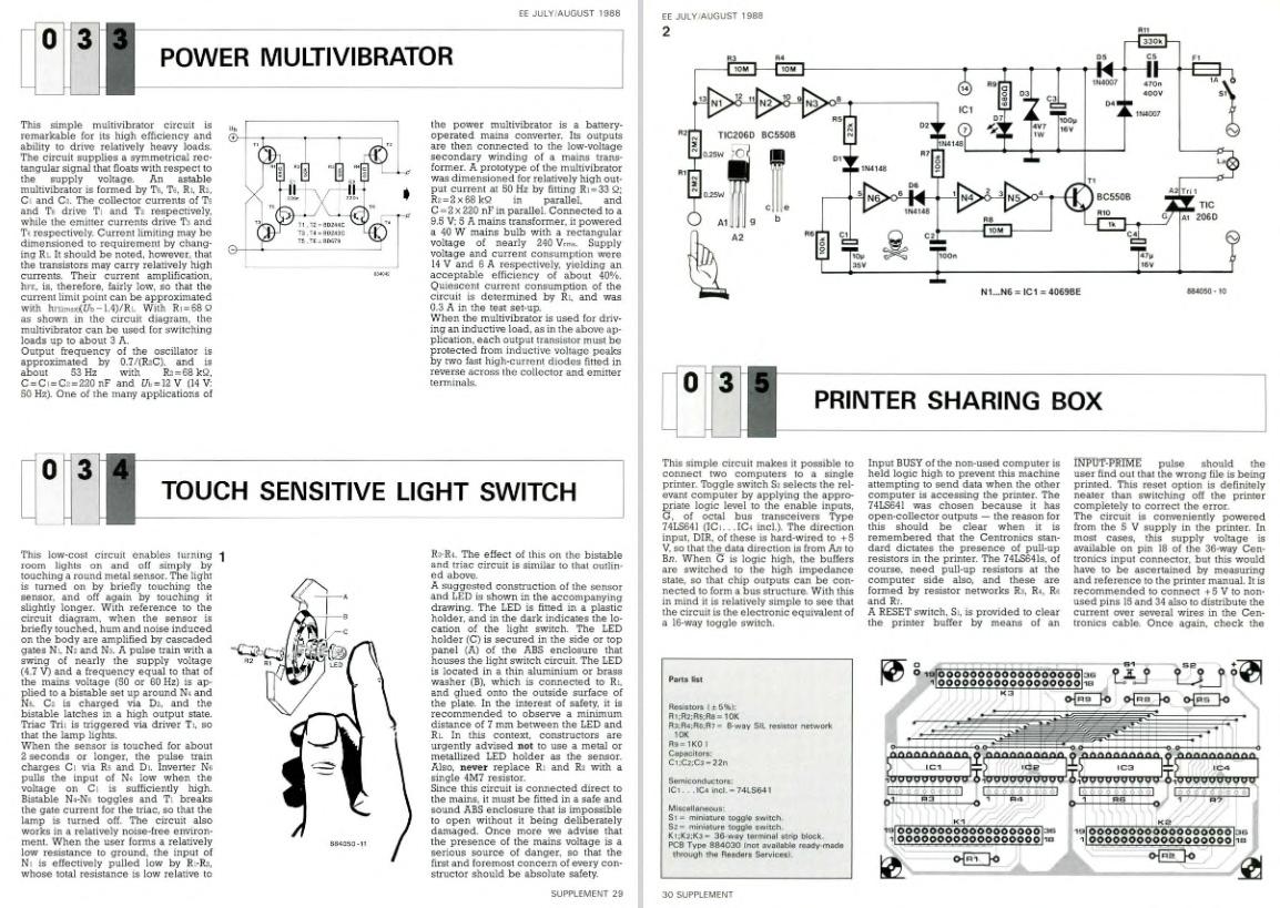
The Elektor Junior Computer in 1980. Projects from 1988! Elektor published a power multivibrator, a touch-sensitive light switch, and a printer sharing box.
Wi-Fi-Based Person Detection on an ESP32
When Your Router Becomes a Motion Sensor
By Saad Imtiaz (Elektor)
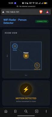
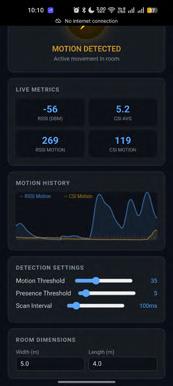
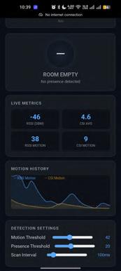
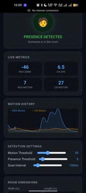
This article walks through the design of a single-ESP32 person detector that uses only Wi-Fi signal disturbance — with no cameras, PIR, or radar modules — to tell whether a room is empty, occupied, or someone is actively moving. The system pairs an ESP32-S3 with any standard 2.4 GHz router and applies a multistage variance pipeline to both RSSI and channel state information (CSI). The result is a real-time web dashboard that updates at 10 Hz over WebSocket, served directly from the ESP32. Along the way, we look at what CSI actually is, why the new IEEE 802.11bf standard matters, and how a few well-chosen DSP stages turn a noisy radio measurement into a stable detection signal.
I stumbled across a video where a security researcher walked through how Wi-Fi routers can be turned into passive surveillance tools, capable of detecting people moving inside a room without any camera, microphone, or wearable on the person being tracked. A follow-up search led me to a project that demonstrated the same effect on a hobbygrade ESP32 setup. The claim was striking enough that I wanted to see how well it actually held up when I tried to build it myself, on my hardware and network.
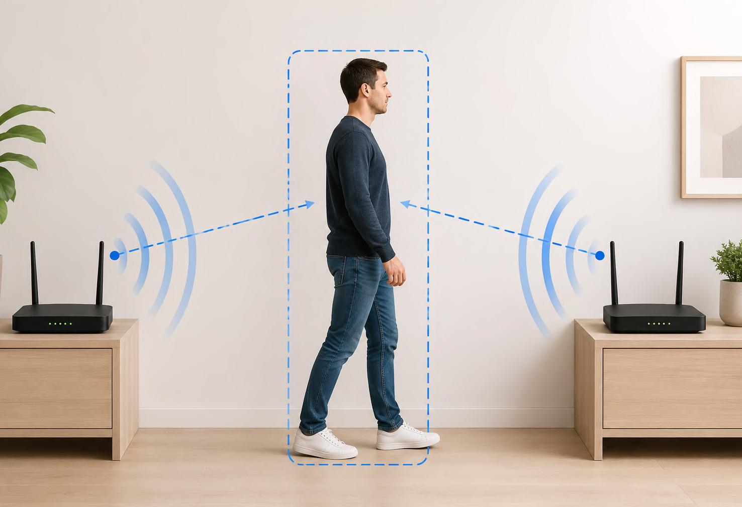
The mechanism, once you look at it, is really simple. A human body is roughly 60% water, and water absorbs and reflects 2.4 GHz radio waves rather effectively, which happens to be exactly the band most consumer Wi-Fi operates in. Every Wi-Fi frame the router transmits reaches the receiver over multiple paths at once: a direct line-of-sight path and several reflected paths bouncing off walls, furniture, and bodies in the room. When someone moves through that space, the geometry of those paths changes. Some paths get blocked, others get strengthened, and the combined signal at the receiver fluctuates in a pattern that an empty room simply does not produce. A receiver that samples this disturbance often enough and processes it carefully can tell whether the room is empty, occupied, or actively in motion, without ever having to “see” the person in any conventional sense.
This is also why the same capability is genuinely concerning when it sits outside the user’s control. A malicious actor with privileged access
Image generated with ChatGPT
to a Wi-Fi router (or, in more advanced setups, a device sniffing on the same channel as the target network) can, in principle, infer when a building is occupied, count roughly how many people are inside, and identify activity patterns over time. There is no LED to indicate it is happening, no camera lens for someone to spot, and 2.4 GHz signals pass through most interior walls. Researchers have been publishing on this class of attack for more than a decade, and the new IEEE 802.11bf sensing standard finalized in 2024 has only sharpened the discussion around how this kind of capability should be exposed responsibly.
On the other side, the same technique is interesting for hobbyists. When you are the one running the receiver on your own network, those signal disturbances become a free presence sensor that you can layer on top of hardware you already own. A hallway light (that currently would rely on a PIR module) can be triggered from an ESP32 already sitting on the network, with no extra sensing module to mount. A battery-powered temperature/humidity node, the kind many of us already run on Home Assistant, can be extended with a few hundred lines of firmware to also report whether the room is occupied. The same node that has been quietly reporting “22°C, 48% RH” for the last year can start reporting “presence detected” without changing a single component on the PCB. The detection is not as crisp as a dedicated PIR or mmWave sensor (we will get to the limitations later), but for plenty of practical applications, it is good enough, and it costs nothing extra.
In this article, I’ll walk through how the system measures those disturbances, how the firmware turns the raw signal into a stable detection output, and what the code actually looks like on an ESP32-S3. Along the way, we’ll look at channel state information (CSI), the IEEE 802.11bf
What is IEEE 802.11bf?
Until recently, using Wi-Fi for sensing lived outside the standard. That changed in 2024, when the IEEE approved 802.11bf, the first Wi-Fi amendment dedicated specifically to sensing. The full standard was published as 802.11bf-2025.
It defines how compliant devices exchange the measurements needed for sensing, how access points and clients coordinate the sensing session, and how those measurements integrate with existing 802.11 frames without breaking communication. It targets the same license-exempt bands that current Wi-Fi already uses (1 GHz to 7.125 GHz) and extends to millimeter-wave frequencies above 45 GHz.
The hobby-grade trick this article uses (extracting CSI from an ESP32) is the same primitive that the next generation of routers will expose officially. The IEEE expects 802.11bf-enabled devices to support presence detection, fall detection, breathing-rate monitoring, gesture recognition, and intrusion alerts. This project is a prototype of that future, built with parts on a desk today.
standard, and a few digital signal processing patterns that are worth keeping in your toolbox even outside this specific project.
The Hardware
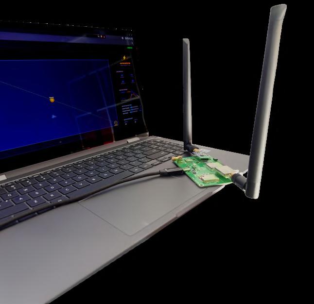
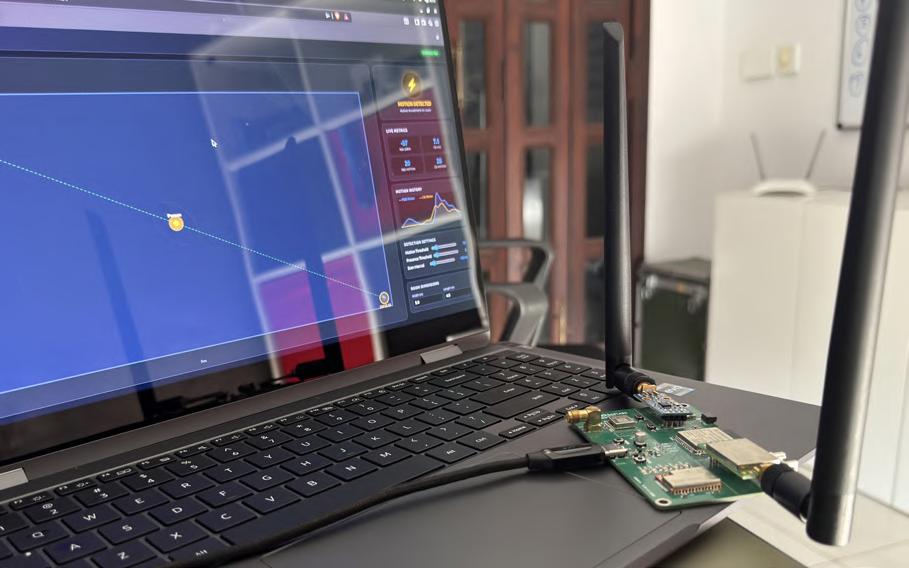
The hardware list is short: one ESP32-S3-WROOM-1, a standard 2.4 GHz Wi-Fi router already in the room, and nothing else. For this project, I used the ESP32-S3 on the Multi RF Dev Board [1], one of my recent projects that integrates six RF technologies onto a single board (Figure 1). The overall data flow is summarized in Figure 2. The cost of adding presence detection to an existing node is effectively zero.
The real challenge is not capturing just a Wi-Fi disturbance, since every Wi-Fi device does that constantly, but distinguishing a meaningful disturbance from the natural noise floor of an indoor radio link, which already fluctuates by several decibels on its own. A walking person and a microwave oven on the floor below can produce signal swings of similar magnitude over a single second. The solution is a dual-source approach: the ESP32 reads two completely different views of the same signal and runs both through the same change-detection pipeline.
and CSI. Both feed the signal processor, whose output goes to a web server and serial debug.
Figure 1: The ESP32-S3 on the Multi RF Dev Board, router in the background, and the live web dashboard on the laptop screen.
Figure 2: System block diagram. The router and ESP32-S3 form a Wi-Fi link that the firmware reads as both RSSI
Walter the Compact IoT Module
ESP32-S3
SoC, LTE-M/NB-IoT 5G Modem, and GNSS Receiver
By Dr. Claus Kühnel (Switzerland)
The Belgian company DPTechnics BV offers a range of IoT building blocks, including a remarkable board called Walter. The controller board is an “Open-Source Multifunction IoT System-on-Module” that combines an ESP32-S3 microcontroller with an LTE-M/NB-IoT modem and a GNSS receiver. This article shows how easily measurement data from connected sensors can be visualized.
Various wireless technologies are available today for IoT applications. All major suppliers provide LoRaWAN or LTE-M/NB-IoT modules, and the user or the application decides which technology will be used.
When low power consumption, long range, small data volume, and broad independence from existing infrastructure are important, LoRaWAN offers certain advantages. However, a gateway to the Internet is required in order to reach a LoRaWAN network server (LNS).
Assuming coverage by a mobile network, LTE offers higher data throughput and mobility. Both LTE-M (Cat-M1) and NB-IoT (Narrowband IoT) are cellular standards from the LTE family and were developed specifically for the Internet of Things. However, they differ in several key respects. LTE-M offers higher data rates, real-time communication, mobility, and roaming, and even voice transmission is possible. NB-IoT, on the other hand, has much lower energy consumption and, as a result, longer battery life, as well as high building penetration.
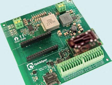
Under the QuickSpot brand, the Belgian company DPTechnics BV offers a range of IoT building blocks intended to support users in product development. This includes a remarkable product called Walter, an “Open-Source Multifunction IoT System-on-Module” (SoM) that
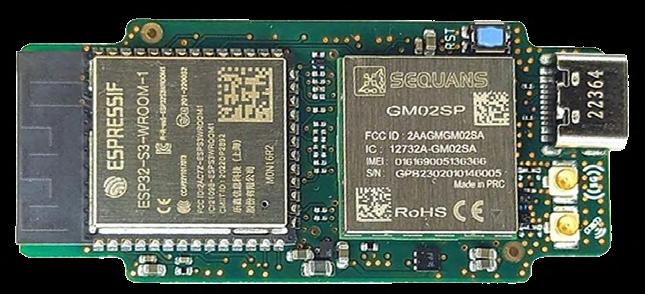
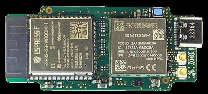
combines an ESP32-S3 microcontroller with a Sequans GM02SP LTE-M/NB-IoT modem and a GNSS receiver. The board supports various wireless options such as Wi-Fi, Bluetooth, LTE-M, NB-IoT, and GPS, and was designed for easy integration into IoT projects. The module is fully certified (CE, FCC, IC, UKCA, RCM) and is supplied with open-source software libraries for platforms such as Arduino, MicroPython, and ESP-IDF.
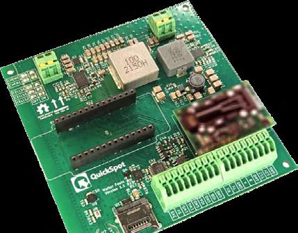
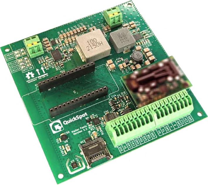
The “Walter Feels” carrier board provides additional interfaces and sensors, making rapid prototyping and development much easier.
Walter Controller Board
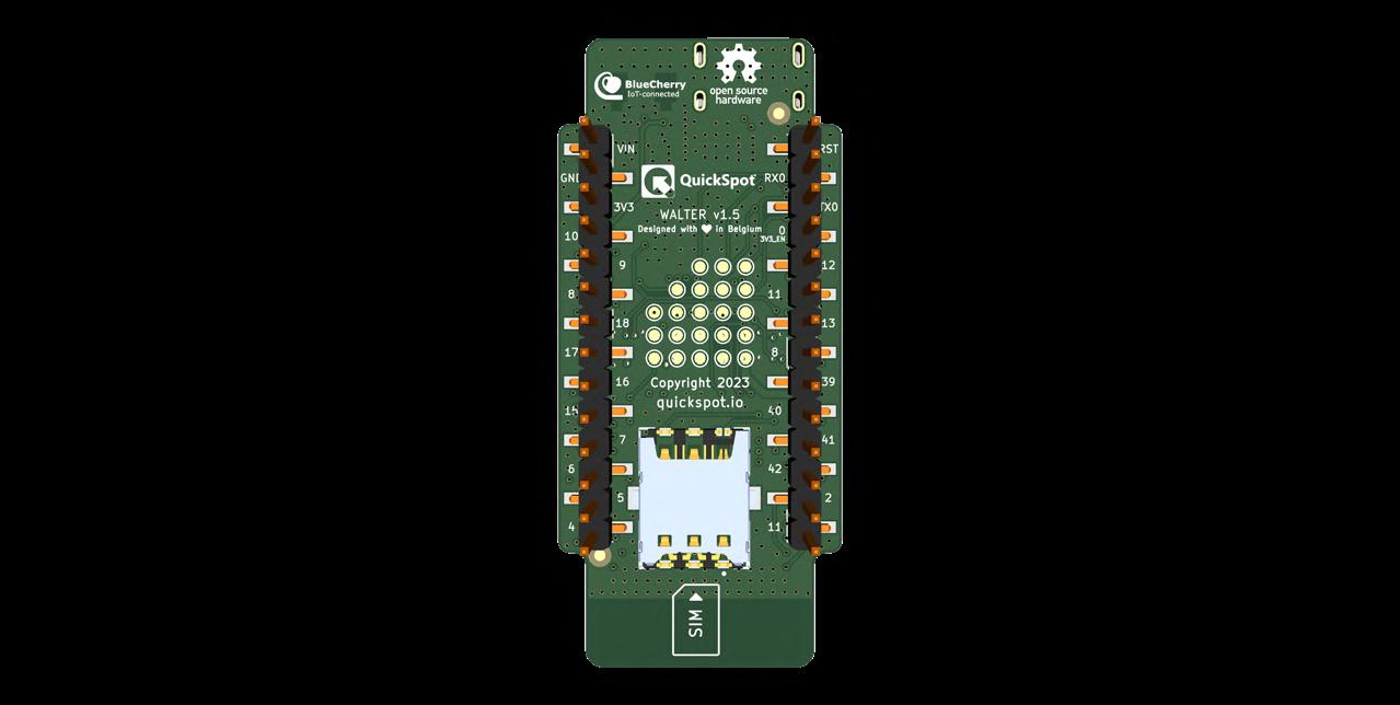
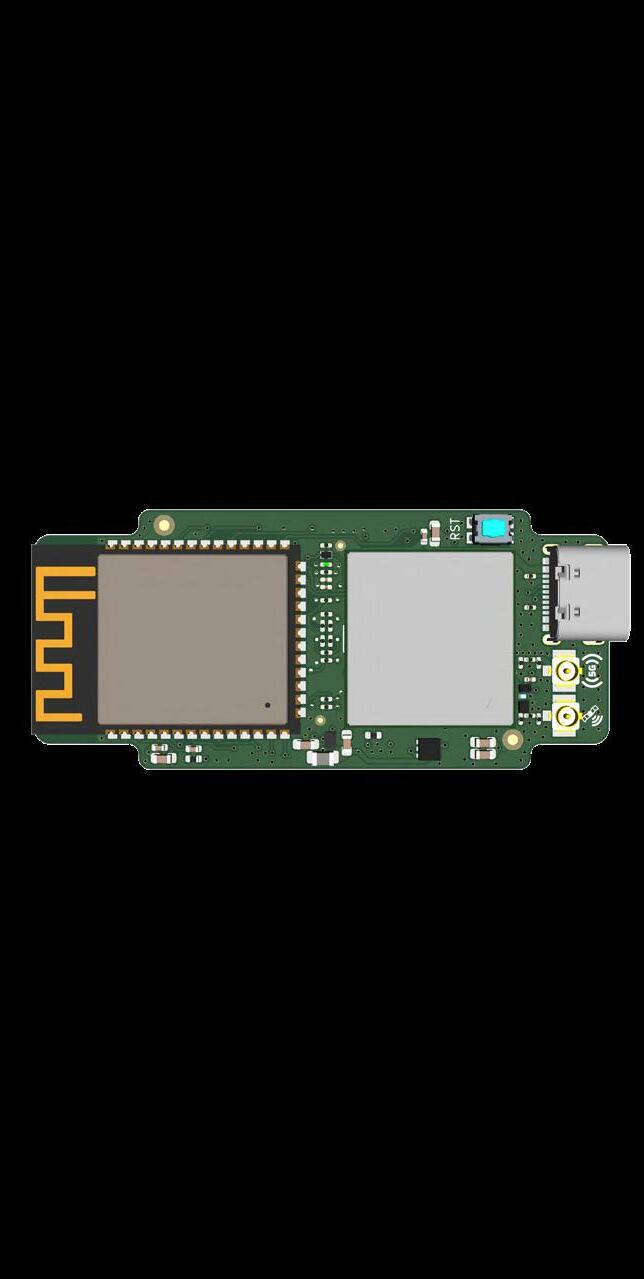
Despite the two modules, the ESP32-WROOM-1 and the GM02SP module, the board remains very compact, with a very small form factor of just 55 mm × 24.8 mm (Figure 1). The controller module based on the ESP32-S3 makes it possible to route any I/O function to any desired I/O pin, enabling free design of a baseboard. As can be seen in Figure 2, the board is pin- and footprint-compatible with the GPy from Pycom (unfortunately discontinued, but still available). Existing Pycom expansion modules can therefore still be used with Walter for prototyping, and conversely, in an existing Pycom application, a GPy can easily be replaced by a Walter board. The Walter board is equipped with:
> ESP32-S3-WROOM-1-N16R2 microcontroller with Xtensa dual-core 32-bit LX7 CPU, 16-MB quad-SPI flash memory, and 2-MB quad-SPI PSRAM
Figure 1: Despite the two fairly large SoC modules, the Walter board has compact dimensions (all images, unless created by the author, courtesy of DPTechnics BV).
> 802.11 b/g/n Wi-Fi 4 with 150 Mbit/s and Bluetooth 5 Low Energy with 2 Mbit/s, integrated trace antennas
> Sequans GM02SP 5G modem: dual-mode LTE-M / NB-IoT (NB1, NB2), 3GPP LTE Release 14 (upgradeable to Release 17), integrated LNA and SAW filters for GNSS reception, GNSS with GPS and Galileo constellations, RF connectors (u.FL) for GNSS and 5G antennas
> Nano-SIM card holder
Walter has several communication interfaces. If you want to use LTE, an LTE antenna must be connected, otherwise the RF front end of the modem may be irreversibly damaged. The following antennas
> LTE: Taoglas FXUB63.07.0150C (from various distributors, among others: [4])
> 24 freely available GPIOs; UART, SPI, I2C, CAN, I2S, and SD (on any I/O pin); ADC, DAC, and PWM available in the ESP32-S3; software-controlled 3.3-V output; USB Type-C connector for program upload and debugging; onboard reset button.
You can find the current board schematic at [1].
Walter Feels Baseboard
The open-source baseboard called “Walter Feels,” shown in Figure 3, stands out because of its practical peripheral features:
> Versatile power supply options through a wide operating voltage range (2.5…26 VDC) with MPPT input for power supply via a solar cell and/or various battery technologies (LiFePO4, Li-Ion, lead-acid).
> Onboard sensors for temperature, humidity, air pressure, 6DoF IMU, and connections for external sensors such as the Sensirion SCD30 CO2 sensor, which is not populated in the standard configuration.
> Numerous interfaces, including RS232, RS485, SDI-12, CAN bus, and various outputs (3.3 V, 5 V, 12 V) for flexible connection options.
> I2C battery and power supply management.
> Support for MicroSD cards.
> Compatible with the Takachi PFF13-4-13W enclosure [2] for easy integration.
You can find the schematic of the Feels baseboard at [3].
> GNSS: Taoglas FXP611.07.0092C (from various distributors, among others: [5])
The board works only with passive GNSS antennas, because no phantom power is available at the GNSS antenna connector. LNA and SAW filters are present on the module. If you want to use only the ESP32-S3’s Wi-Fi and Bluetooth connection, no external antenna is required, because those two antennas are integrated on the module.
For power supply, a standard USB Type-C cable from your PC, a USB power supply, or a power bank can be used, but it is also possible to
Figure 2: Pinout of the Walter board.
Figure 3: The Walter Feels application board. The CO2 sensor is not populated in the standard configuration.
Ecologging A Modular Environmental IoT Station for Field Research
By Pierre Bordenave and Philippe Chaumeil (France)
A low-cost, modular Aduinobased platform can collect air, soil, and water data with research-level reliability. Built around stackable shields, solar power, and flexible 4G or LoRa links, the system is designed to be practical, repairable, and scalable for real field use.
Acquiring environmental data is essential in personal, industrial, and research settings alike. Reliable, low-cost access to large volumes of data remains a constant challenge. The “Autonomous Sensor Node V2.0” article in Elektor [1] addressed this issue.
Research-grade meteorological systems from suppliers such as Campbell Scientific, LI-COR, or OTT can cost around €8,000, while cheaper alternatives are often difficult to repair or adapt once a sensor or communication module fails. The ECOLOGGING station was developed to bridge that gap: a complete, modular, and scalable environmental monitoring system with a good data quality/cost ratio, built from replaceable parts and open enough for users to modify, repair, and extend themselves.
The ECOLOGGING Approach
ECOLOGGING Instrumented Stations use stackable shield modules for simple, scalable integration and support the acquisition of
environmental data from air, soil, and water with a level of reliability suitable for research. The stations are designed to be modular, robust, and repairable. Their construction relies on standard connections, making field installation practical and durable. Because manufacturers already offer a wide variety of shields (Arduino) and HATs (Raspberry Pi), there is often no need for soldering or for designing custom circuits and PCBs, which keeps the system accessible even to beginners.
The Arduino platform was a natural choice because of its accessibility, long-term availability, and large user community, all of which make the system easier for a broad audience to adopt.
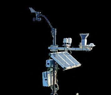
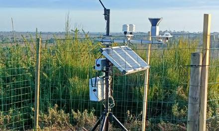
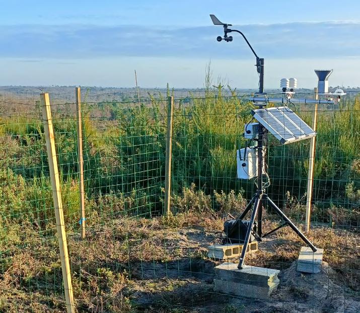
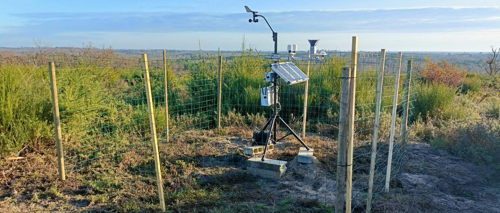
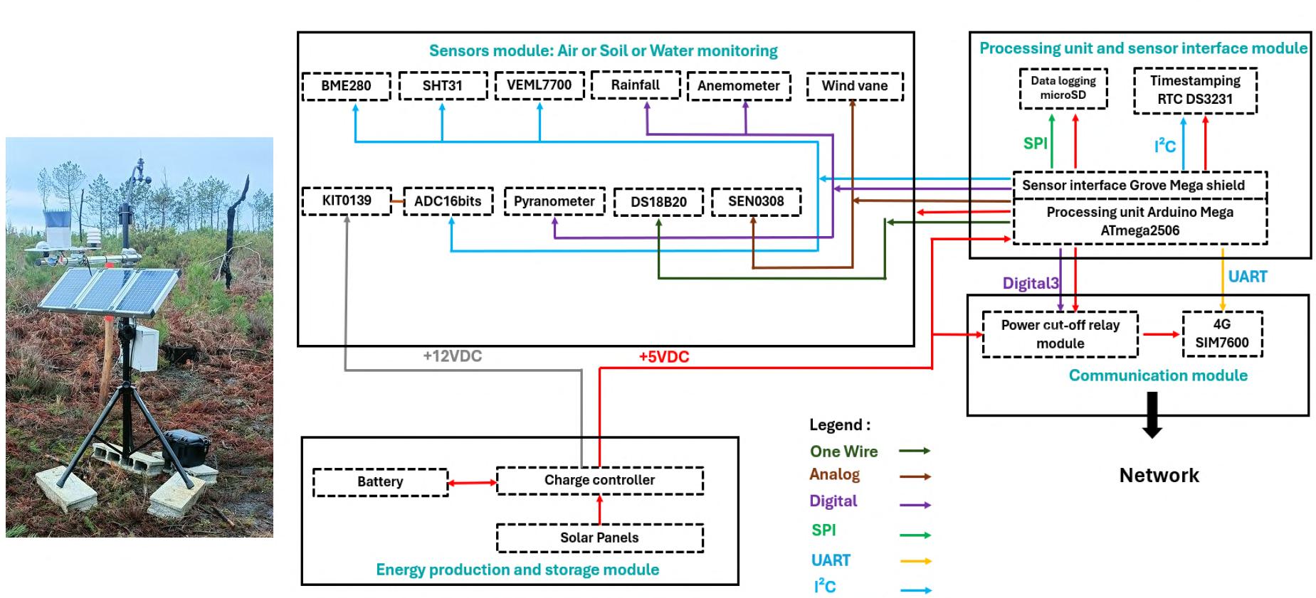
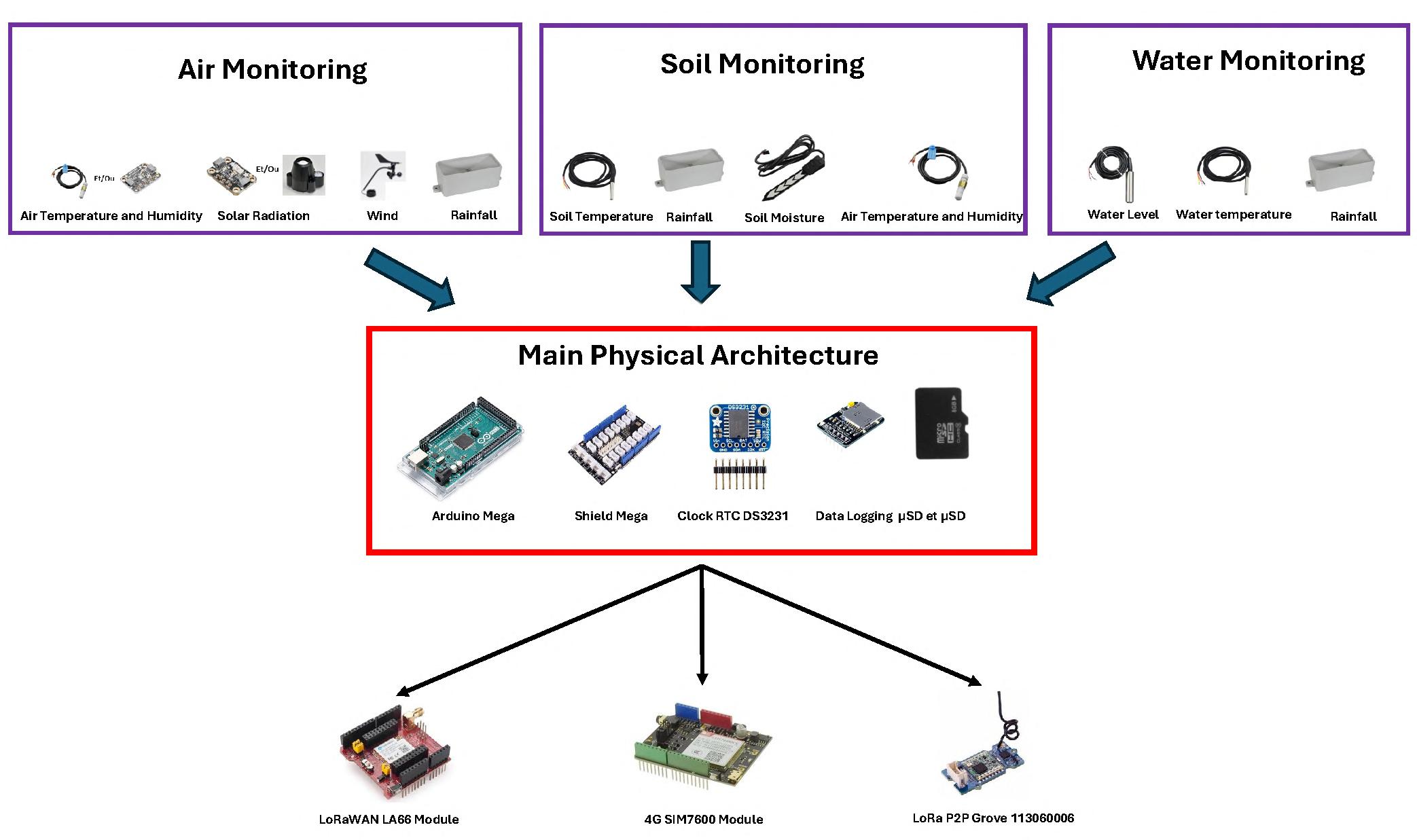
The project’s main challenges included properly sizing the power system to ensure station autonomy, selecting high-quality sensors, ensuring reliable data acquisition and storage, and designing a common hardware architecture suitable for different station configurations, including the processing unit and interface modules. Figure 1 shows the project deployed in the field, as well as the data flow diagram. Figure 2 provides an overview of the sensors, boards and modules.
Another challenge was providing communication capabilities to reduce the need for on-site maintenance. Although IoT hardware is now widely available, integrating existing Arduino shields still raises several practical issues.
Energy Generation and Storage Module
To ensure energy autonomy, the IoT stations were powered by 10 W photovoltaic panels. Their compact size makes it possible to adjust
the number of panels according to the application and local environmental conditions. Two or three panels are connected to a charge controller and battery pack. Numerous configurations were tested, covering wiring methods (individual, series, or parallel), controller options, and battery types.
For Li-ion batteries, the SunFlower DFR0535 controller [2] was used. This module supports only 3.7 VDC batteries, accepts up to 12 VDC / 20 W from solar panels, is compact, and provides multiple output voltages: 3.3 VDC, 5 VDC, 9 VDC, and 12 VDC.
For lead-acid batteries, the SOL10U3 controller [3] with 12 VDC batteries and multiple solar panels, was used. Its current consumption is 6 mA, and it provides 12 VDC and 5 VDC outputs.
These tests made it possible to optimize system performance and reliability under varying conditions. In Table 1, you see the battery types versus operating time, while Table 2 shows operating time versus sensor station type.
To validate autonomy under real operating conditions, the weather sensor stations collected data every 20 s and transmitted hourly averages over 4G. The other stations recorded data every minute and transmitted half-hour averages.
The selected configuration used the SOL10U3 controller, which proved better-suited to field conditions. It can handle higher-capacity batteries, supports heavier loads more reliably, and allows the use of higher-capacity solar panels.
The ECOLOGGING Instrumented Weather Station and its data flow.
Figure 1:
Figure 2: ECOLOGGING boards, sensors and modules.
By Pascal Rondane (France)
Control a water heater remotely using a Telegram interface and an ESP32-based module. Switch it on or off and monitor its status from a smartphone, without needing a full home automation system. Simple hardware and Arduinobased software make it an easy way to reduce energy use when hot water is only needed occasionally.
I designed this module for a friend’s daughter, a student who wanted to be able to turn off her water heater when she was away for several days, as her budget is very tight. For example, if she leaves for a week, she can turn it back on the day before she returns (if the water heater operates during off-peak hours at night) to ensure she has hot water upon arrival.
The water heater accounts for a significant portion of a household’s energy consumption. Even in standby mode, it consumes energy to maintain a constant water temperature. In a vacation home, this energy expense is unnecessary, which is where this setup proves useful. She requested a simple solution that does not require a home automation server. Therefore, I adapted an electronic module that I use to control my alarm system.
My control module allows the water heater to be turned on and off remotely via the Telegram interface. It also sends an acknowledgement message of the command. This setup can also be used for other applications, such as starting a sump pump.
The Hardware
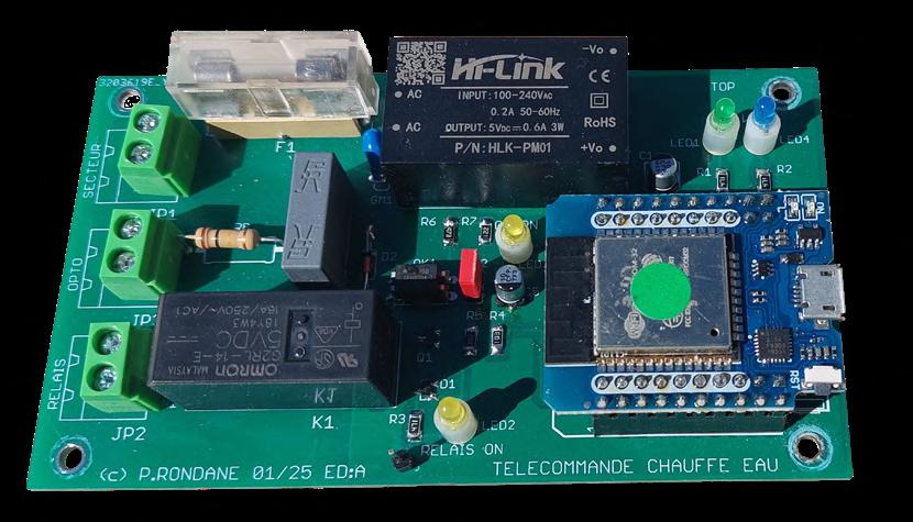
The control electronic board is relatively simple and uses 1206 SMD and through-hole components, making it easy to assemble and reproduce. The interface is supplied by 230-V mains power, which is converted to 5 V by an HI-LINK module; the green LED1 indicates the presence of this voltage. The unit is controlled by an ESP32, and the blue LED2 lights up to indicate a successful connection to the Wi-Fi router. The complete assembled board is shown in Figure 1, where the main components, including the ESP32 module, power supply, and relay, can be clearly identified.
The complete circuit diagram of the interface is shown in Figure 2. This schematic provides an overview of the power supply, ESP32 control section, relay driver, and mains detection circuitry. The water heater is controlled on/off by relay K1. The yellow LED3 indicates its operating status. The relay is wired in normally closed (NC) mode, which ensures that the water heater continues to operate in the event of a system failure.
Figure 1: Telegram water heater interface control board.