books books
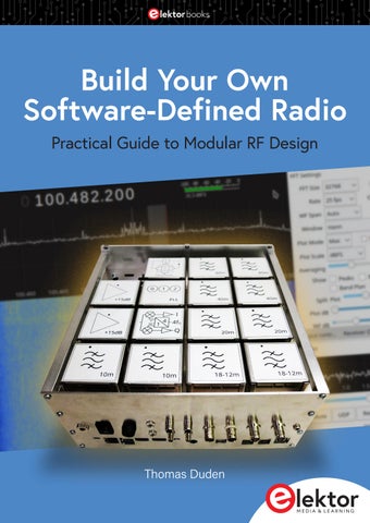
Build Your Own Software-Defined Radio Practical Guide to Modular RF Design
Thomas Duden
Build Your Own Software-Defined Radio
Practical Guide to Modular RF Design
● Thomas Duden
Build Your Own Software-Defined Radio
● This is an Elektor Publication. Elektor is the media brand of Elektor International Media B.V.
PO Box 11, NL-6114-ZG Susteren, The Netherlands Phone: +31 46 4389444
● All rights reserved. No part of this book may be reproduced in any material form, including photocopying, or
storing in any medium by electronic means and whether or not transiently or incidentally to some other use of this publication, without the written permission of the copyright holder except in accordance with the provisions of the Copyright Designs and Patents Act 1988 or under the terms of a licence issued by the Copyright Licencing Agency Ltd., 90 Tottenham Court Road, London, England W1P 9HE. Applications for the copyright holder’s permission to reproduce any part of the publication should be addressed to the publishers.
● Declaration The author, editor, and publisher have used their best efforts in ensuring the correctness of the information contained in this book. They do not assume, and hereby disclaim, any liability to any party for any loss or damage caused by errors or omissions in this book, whether such errors or omissions result from negligence, accident or any other cause. All the programs given in the book are Copyright of the Author and Elektor International Media. These programs may only be used for educational purposes. Written permission from the Author or Elektor must be obtained before any of these programs can be used for commercial purposes.
● I SBN 978-3-89576-710-4 eBook ● © Copyright 2026 Elektor International Media www.elektor.com
Editor: Glaucileine Vieira
Elektor is the world's leading source of essential technical information and electronics products for pro engineers, electronics designers, and the companies seeking to engage them. Each day, our international team develops and delivers high-quality content - via a variety of media channels (including magazines, video, digital media, and social media) in several languages - relating to electronics design and DIY electronics. www.elektormagazine.com
●2
Contents
Contents Chapter 1 • Introduction ���������������������������������������������������������������������������������������������7 Chapter 2 • Mechanics �����������������������������������������������������������������������������������������������9 2.1 The RF Brick Template ���������������������������������������������������������������������������������������� 9 2.2 The Chassis �����������������������������������������������������������������������������������������������������14 2.3 The 19 Inch Module Carrier �������������������������������������������������������������������������������16 2.4 Concluding Remarks �����������������������������������������������������������������������������������������19 Chapter 3 • Bridges ���������������������������������������������������������������������������������������������������21 3.1 The USB Isolator Bridge �����������������������������������������������������������������������������������21 3.2 I2C Level Shifter Bridge ������������������������������������������������������������������������������������25 3.3 The I²C Power Switch Bridge �����������������������������������������������������������������������������27 3.3 Examples of the Use of Bridges �������������������������������������������������������������������������31 Chapter 4 • Signal Chains with RF Bricks �����������������������������������������������������������������33 4.1 The Antenna ���������������������������������������������������������������������������������������������������33 4.1.1 What the antenna does not receive, no amplifier can pick up from the noise ���������34 4.1.2 An antenna belongs outside ���������������������������������������������������������������������������34 4.1.3 Lightning and surge protection is essential �������������������������������������������������������34 4.1.4 An Antenna has frequency-dependent properties �����������������������������������������������34 4.1.5 The Symmetrical feed line avoids common mode interference �����������������������������35 4.1.6 Signal cosmetics �������������������������������������������������������������������������������������������36 4.2 The Band Filter Brick �����������������������������������������������������������������������������������������36 4.2.1 Excursus: working with the NanoVNA ���������������������������������������������������������������38 4.2.1.1 Installing the NanoVNA software on the host �������������������������������������������������40 4.2.1.2 Calibration of the NanoVNA �������������������������������������������������������������������������42 4.2.2 Calculating filter data yourself �������������������������������������������������������������������������44 4.2.3 Structure of an example filter �������������������������������������������������������������������������52 4.2.3.1 Winding the toroidal coil according to the table �����������������������������������������������53 4.2.3.2 Measuring the inductance, adjusting the number of turns �������������������������������53 4.2.3.3 Set up the first resonant circuit, measure resonant frequency �������������������������53 4.2.3.4 Set up the second resonance circuit and measure the resonance point �������������55 4.2.3.5 Set up and adjustment of the resonant parallel circuit (not tapped) �����������������56
●3
Build Your Own Software-Defined Radio
4.2.3.6 Set up and adjust the tapped parallel circuit ��������������������������������������������������59 4.2.3.7 Compensating for the pole ���������������������������������������������������������������������������60 4.3 The Preamplifier Brick ���������������������������������������������������������������������������������������63 4.4 The PLL Brick ���������������������������������������������������������������������������������������������������66 4.5 The Lima Demodulator Brick �����������������������������������������������������������������������������70 4.6 The Integrated Double Demodulator �������������������������������������������������������������������73 4.7 The Direct Conversion Signal Chain ��������������������������������������������������������������������75 4.8 The Multiband Direct Conversion RX �������������������������������������������������������������������78 4.9 The 45MHz Narrow Band Brick ���������������������������������������������������������������������������83 4.9.1 The double superhet signal chain ���������������������������������������������������������������������84 Chapter 5 • Bricks for RF Measurements �����������������������������������������������������������������86 5.1 Test Signals – One Single Spectral Line ���������������������������������������������������������������86 5.2 Test Signals - Two Spectral Lines �����������������������������������������������������������������������87 5.2.1 The Low Distortion Generator Brick �����������������������������������������������������������������88 5.2.2 The Wheatstone-bridge power combiner �����������������������������������������������������������90 5.3 Test Signals — Noise �����������������������������������������������������������������������������������������94 5.3.1 5 Hz Bandwidth cut from the center, please �����������������������������������������������������94 5.3.2 The noise power ratio (NPR) ���������������������������������������������������������������������������95 5.3.3 The notch filter brick �������������������������������������������������������������������������������������96 5.3.4 Alternatives to NPR measurement with the notch filter ������������������������������������� 104 5.3.5 What information do the different approaches provide? ����������������������������������� 105 5.3.6 The noise generator brick ����������������������������������������������������������������������������� 105 5.3.7 The broadband amplifier brick with MMICs ����������������������������������������������������� 112 5.3.8 The noise bridge ����������������������������������������������������������������������������������������� 115 Chapter 6 • Useful Accessories �������������������������������������������������������������������������������118 6.1 The ATU-100 Antenna Tuner ��������������������������������������������������������������������������� 118 6.1.1 Changing the firmware of the ATU-100 ����������������������������������������������������������� 120 6.1.2 The Mechanical Model ����������������������������������������������������������������������������������� 122 6.2 The X-Phase QRM Eliminator ��������������������������������������������������������������������������� 123 6.2.1 Compensating the QRM ������������������������������������������������������������������������������� 123 6.2.2 Reverse polarity protection and fuse protection ����������������������������������������������� 125
●4
Contents
6.2.3 Assembly ��������������������������������������������������������������������������������������������������� 126 6.2.4 Operating the X-Phase QRM Eliminator ����������������������������������������������������������� 127 Chapter 7 • Cables and Wires ���������������������������������������������������������������������������������128 Chapter 8 • Sound Cards ���������������������������������������������������������������������������������������130 8.1 The Internal Sound Card ��������������������������������������������������������������������������������� 130 8.2 USB Stick with 24-Bit Sound Card (CM6533) ����������������������������������������������������� 131 8.3 Asus Xonar U7 MKII ��������������������������������������������������������������������������������������� 132 8.4 Behringer U-PHORIA UMC404HD ��������������������������������������������������������������������� 134 8.5 Conclusion ����������������������������������������������������������������������������������������������������� 137 Chapter 9 •PC Host Software ���������������������������������������������������������������������������������138 9.1 SoapySDR ����������������������������������������������������������������������������������������������������� 138 9.1.1 Tweaking the SoapyAudio module ����������������������������������������������������������������� 140 9.1.2 Adapt SoapyAudio to the new rtaudio7 ����������������������������������������������������������� 146 9.2 GQRX ����������������������������������������������������������������������������������������������������������� 154 9.2.1 Integrated tuning with gqrx-hamlib ��������������������������������������������������������������� 160 9.2.2 Compile GQRX yourself ��������������������������������������������������������������������������������� 164 9.2.3 Adding additional functionality to GQRX ��������������������������������������������������������� 170 9.2.4 tweak gqrx-hamlib ��������������������������������������������������������������������������������������� 173 9.2.5 Increase the bandwidth of PulseAudio ����������������������������������������������������������� 177 9.3 CubicSDR ����������������������������������������������������������������������������������������������������� 180 9.4 SDRPP ����������������������������������������������������������������������������������������������������������� 188 9.5 Summary ����������������������������������������������������������������������������������������������������� 191 Chapter 10 • GnuRadio �������������������������������������������������������������������������������������������193 10.1 Control the SDR Hardware with GnuRadio ������������������������������������������������������� 193 10.1.1 Create the Python Arduino control block ������������������������������������������������������� 194 10.2 Installing the First GUI Elements ������������������������������������������������������������������� 203 10.2.1 FrequencySink and Waterfall Sink ��������������������������������������������������������������� 203 10.2.2 Controlling the frequency display with messages ������������������������������������������� 208 10.2.3 Using the frequency selector ����������������������������������������������������������������������� 211 10.3 SSB Demodulation ��������������������������������������������������������������������������������������� 212 10.3.1 The Weaver scheme ����������������������������������������������������������������������������������� 213
●5
Build Your Own Software-Defined Radio
10.3.2 GUI Gain Controls ������������������������������������������������������������������������������������� 217 10.3.3 Improved Weaver scheme ��������������������������������������������������������������������������� 218 10.3.4 Optimized messaging ��������������������������������������������������������������������������������� 220 10.3.5 Adjustable filter bandwidth ������������������������������������������������������������������������� 222 10.4 Control More Hardware Options via the Arduino ����������������������������������������������� 223 10.4.1 Expanding the TS850-CAT interface in the Arduino ����������������������������������������� 223 10.4.2 Extending the serial control block ���������������������������������������������������������������� 226 10.5 Once Again: Optimize the Messaging �������������������������������������������������������������� 228 10.6 Cleaning Up the GUI ������������������������������������������������������������������������������������� 230 10.7 Summary and Outlook ����������������������������������������������������������������������������������� 231 Chapter 11 • “SDR” with FPGAs �����������������������������������������������������������������������������232 11.1 VHDL ����������������������������������������������������������������������������������������������������������� 232 11.2 Select FPGA and IDE ������������������������������������������������������������������������������������� 233 11.3 Select the Data Converter ����������������������������������������������������������������������������� 234 11.4 Learn How to Use Scilab ������������������������������������������������������������������������������� 235 11.4.1 Install Scilab ��������������������������������������������������������������������������������������������� 235 11.5 Installing the FPGA Toolchain ������������������������������������������������������������������������� 236 11.5.1 Install the latest Intel® Quartus version ������������������������������������������������������� 236 11.5.2 Starting the help system ����������������������������������������������������������������������������� 239 11.5.3 Install the Arrow programmer ��������������������������������������������������������������������� 241 11.6 Bringing the FPGA to life ������������������������������������������������������������������������������� 242 11.6.1 Setting up the FPGA shield ������������������������������������������������������������������������� 242 11.6.2 Hello World – make an LED flash ����������������������������������������������������������������� 245 11.6.2.1 Configure the project ������������������������������������������������������������������������������� 245 11.6.2.2 Create a block diagram from standard functions ����������������������������������������� 247 11.6.2.3 Define the timing constraints ������������������������������������������������������������������� 261 11.6.2.4 Synthesizing the design ��������������������������������������������������������������������������� 262 11.6.2.5 Using the pin planner ������������������������������������������������������������������������������� 263 11.6.2.6 Finalizing the synthesis ��������������������������������������������������������������������������� 265 11.6.2.7 Loading the design into the FPGA temporarily ��������������������������������������������� 266 11.6.2.7 Loading the design permanently into the FPGA ������������������������������������������� 268
●6
Contents
Chapter 12 • Developing Blocks for PC-Independent FPGA Receivers with SSB/CW Filters ���������������������������������������������������������������������������������������������������������������������270 12.1 The Delta Sigma DAC ����������������������������������������������������������������������������������� 270 12.1.1 Simplified principle of operation ������������������������������������������������������������������� 270 12.1.2 Translation into VHDL ��������������������������������������������������������������������������������� 271 12.1.3 Define the DAC block ��������������������������������������������������������������������������������� 272 12.2 A Simple Sine Wave Generator ����������������������������������������������������������������������� 275 12.2.1 Realization - CORDIC or value table ? ����������������������������������������������������������� 275 12.2.2 Translation into VHDL code ������������������������������������������������������������������������� 278 12.2.3 Create the sine generator block ������������������������������������������������������������������� 279 12.2.4 Testing the sine wave generator block with the DAC ��������������������������������������� 279 12.3 The Differential Amplifier Brick ����������������������������������������������������������������������� 280 12.4 The 24-bit ADC ��������������������������������������������������������������������������������������������� 282 12.4.1 Setting up the 24-bit ADC brick ������������������������������������������������������������������� 282 12.4.2 Reading out the ADC with VHDL ������������������������������������������������������������������� 284 12.5 A Signal Chain for SSB Demodulation ������������������������������������������������������������� 287 12.5.1 Quadrature Sampling ��������������������������������������������������������������������������������� 288 12.5.2 The first FIR low-pass filter ������������������������������������������������������������������������� 290 12.5.3 The Weaver mixer ������������������������������������������������������������������������������������� 296 12.5.4 The second FIR low-pass filter ��������������������������������������������������������������������� 298 12.5.5 Assembling the signal chain ����������������������������������������������������������������������� 299 12.6 The GnuRadio Flowgraph ������������������������������������������������������������������������������� 300 12.7 Optimizations ����������������������������������������������������������������������������������������������� 301 12.7.1 The Anti-Aliasing Filter ������������������������������������������������������������������������������� 302 12.7.2 Inserting a peak value detector ������������������������������������������������������������������� 305 12.7.3 Matching the narrowband signal chain brick to the system impedance ������������� 306 12.7.4 Quadruple oversampling with the LTC2380 ��������������������������������������������������� 309 12.7.5 Tenfold oversampling with the LTC2380 ������������������������������������������������������� 312 12.7.6 Analyzing the effect of oversampling ����������������������������������������������������������� 315 12.7.7 Interpreting the Weaver signal chain as an oversampling filter ����������������������� 318 Chapter 13 • Outlook ���������������������������������������������������������������������������������������������319 Chapter 14 • Sources ���������������������������������������������������������������������������������������������320
●7
Build Your Own Software-Defined Radio
●8
Chapter 1 • Introduction
Chapter 1 • Introduction Today, it seems no longer possible to employ RF technology without Software Defined Radio (SDR). The elegant abbreviation suggests that communications technology has now also converged into a pure software problem that can be easily mastered with a few mouse clicks. To facilitate an easy start with SDR, there is now an almost unmanageable variety of USB plug-in modules and kits on the market. With its tireless ambition, the Linux community has managed to provide libraries for controlling many of the numerous products—a feat that would otherwise be achieved only by large software companies. Connecting a piece of wire or a telescope antenna to the SMA socket of the newly purchased device is easy, as is the selection of the module from the combo box of a ready-made SDR application. For someone who wants to start analyzing signals immediately (e.g., weather radio sensors from the neighborhood, radio signals from airplanes, satellites, etc.), this procedure is maximally efficient and appropriate. Whether a high sensitivity of the receiver can also be achieved in this way, however, depends on many details. With the purchase of the device, a deeper understanding of the signal chain and its weaknesses is delegated to the developers. When using complex host software, you are also faced with a black box, even though these programs have very sophisticated GUI elements that allow a lot of control. All the sub-disciplines – RF technology, electronic circuit design, and digital signal processing, are tough nuts to crack. The easy start with readily fabricated technology can tempt you to become a consumer, or at best, a critical user of the technology. Then, in the face of the high hurdles, it is not unlikely that you will give up your own ambitions. That would be a pity! If you were always the kind of child who had to unscrew everything, you will find the path taken in this book logical, which starts with the hardware: We are developing a modular concept in which the SDR circuit is broken down into its components. A common complication is the mechanically solid and shielded construction; you cannot simply operate a sensitive RF device as a bare circuit board on a desk, at least not in the long run. For this reason, each module has its own metal housing, which is available at low cost as a mass-produced item. For advertising purposes, the building blocks will be called “RF-Bricks”, in reference to the useful interlocking plastic bricks from some major toy manufacturers. A chassis plate, which carries the footprint of the RF bricks in a regular grid, can serve as a base plate for clearly arranged experiments. If the chassis plate is integrated into a 19inch module carrier, the setup can be easily scaled up. Furthermore, the module carrier can seamlessly fit into a standardized 19-inch rack mountable frame, which saves a lot of sheet
●9
Build Your Own Software-Defined Radio
metal work for an enclosure. We process the specific requirements for each RF brick step by step. Then, the modules will be assembled to form a signal chain via their standardized interfaces. The result is a flexible and expandable concept whose complete design data is available in the online material. In this way, you are able to materialize your own ideas. Combine them with other, already well-functioning building blocks at your liking! Components that have proven their functionality remain in your arsenal for further experiments. Some of them are already independently working, small devices that could also be permanently integrated into other setups. Once the signal chain has been created, the connection to existing SDR software (in this book for reception) will be resolved. An Arduino Mega is available on our chassis for this purpose. With the corresponding sketches, it mimics a TS-850 and can therefore be addressed directly from most SDR programs via the hamlib / CAT interface. We compile some of the popular SDR host applications ourselves. The procedures described are intended to encourage you to work with source code. Initially, we only modify the applications to add minor features, e.g., for the frequency control of the SDR hardware, when this appears necessary. Next, GnuRadio will be used. It doesn’t provide you with a very fancy GUI, but it enables a lot of control over the inner workings of the SDR program. This allows us to try out different ideas for demodulators and to understand them better. With a little Python, you are also able to control the frequency of our SDR hardware from within the host program. Finally, we take a brief look at FPGA programming. This topic is so mighty that it will only be explained here using some basic examples. A sensitive monoband receiver is described, which you can easily expand to work with other frequencies and modes. In the end, you will have all the individual parts of a functional entry-level model SDR in your hands. With this, you can embark on your personal journey and extend the technology as you see fit. You could also use the bricks to add more RF gain and frequency selectivity to your purchased SDR. If this results in further RF bricks, this could be a basis for your own publication. Don’t keep it to yourself!
● 10
Chapter 2 • Mechanics
Chapter 2 • Mechanics 2.1 The RF Brick Template Small breakout or evaluation boards are popular for the introduction of new components. These only contain a few components required to operate the advertised new device, as well as some connectors. For the modular SDR concept, we can take a similar approach by mapping each block on our block diagram into an RF brick. This greatly simplifies the PCB design. We choose a standard TEKO 371 sheet steel housing for an RF brick. A template board fits into it, which contains SMA sockets at predefined positions, as well as a double-row pinhead connector. The SMA sockets point vertically downwards. This may not be good enough for some people working with microwaves. For these applications, sockets aligned with the board surface are preferred, and even their center pins are cut in half to avoid bumpy transitions to the adjacent stripline tracks.
Figure 2.1: Left: CAD model of the TEKO 371 housing with holes, not all of them are necessary for every brick. Right: a photo with an example brick In this book, we want to focus on frequencies up to 200 MHz when passing signals between modules in the chassis. This should also be possible “around the corner” without any problems. SMA socket orientation is not a principal restriction. If you want to process GHzfast signals, you can still do this within a single brick and construct a front end with a lower IF. You should also not be discouraged from experimenting. Simply try out whether the orthogonal SMA connector arrangement causes any problems in your specific application.
● 11
Build Your Own Software-Defined Radio
Figure 2.2: Template board (KiCad) If you are designing a new brick, start the PCB design in KiCad by adding the template board to the design. SMA sockets that are not required are then deleted. Sometimes the bricks are passive, in which case the pin header, which is otherwise used to supply operating voltage and control signals, can also be omitted. It takes a little practice to insert the template board and the associated circuit diagram symbols in such a way that the annotation between the two works correctly afterwards: In KiCad, first add the circuit board to the design board (“File | Add board”). Then copy the circuit diagram symbols from the template circuit diagram to the current circuit diagram. Go back to the circuit board view. Use the “Tools | Update schematic from board” tool to restore the annotation between the schematic symbols and the PCB. Experienced RF technicians see the use of a pin header as a wide-open door for RF interference. Ideally, the operating voltage should be supplied with feed-through capacitors. There are three reasons why they are not used here: They are not at all easy for hobbyists to obtain, and their use is also not practical for fast logic signals. The last reason refers to mechanical requirements: As the final connections, the wires of the feed-through capacitors which are inserted through from below would have to be soldered into the circuit board eyelets. This rigid connection is in mechanical competition with the fastening screws. Thus, the capacitor could experience mechanical stress and break when the fastening screws are tightened. If you still don’t like the pinhead connector or your application speaks against the compromise, all design data is available for modification in the online material. When drilling the holes into the bottom of the TEKO 371 housing, you should not mark out the holes with a ruler or calipers, as the housings themselves have significant tolerances. It is easier to place the desired brick circuit board centered onto the outside of the case bottom as a template (possibly fix it with adhesive tape). Then, transfer the necessary hole positions from the board to the case using a thin permanent marker pen. But be careful: The brick circuit boards are not always equipped with symmetrical socket arrays. Please
● 12
Chapter 2 • Mechanics
make sure that you can really see the bottom of the board when marking. This will ensure that the board is oriented exactly as it will be installed later inside. Otherwise, the hole arrangement will come out mirrored.
Figure 2.3: Transferring the drill holes with a fiber-tip pen Once you can see the position of the holes as pen marks on the housing bottom, center punch these positions. To do this, you can either use a classic center punch or you can use a pointed countersink tool in your drill press and drill it slightly into the housing. Support the inside of the housing with a wooden block and do not hammer or press too hard! The housings initially react quite softly to the pressure and could quickly become dented. Once the holes have been mechanically marked, drill a small pilot hole (e.g. D = 2 mm). Sheet steel is unforgiving: Once the drill has found a target close, but offset to the marking, it slightly deforms and goes the wrong way. A special starter drill has a stiffer design and does not go astray so easily - a sensible investment!
Figure 2.4: From left to right: Manufacturing steps for the holes according to the text After drilling the pilot holes, enlarge the four mounting holes to D = 3.2 mm. The drill bit
● 13
Build Your Own Software-Defined Radio
should be sharp to produce spiral chips (otherwise, it scratches, the housing gets hot, and you get a thick burr). Start to drill quickly, then the hole stays round more easily. With too little pressure, the drill will start to dance and produce an unsightly triangle shape. After properly starting, continue working with lighter pressure so that the chip remains thin and controllable. Hold the housing firmly. If the drill bit pushes through the bottom too quickly, the housing tends to pull up on the drill bit (remove your fingers!); this result will also not look presentable. Always use a hold-down device or a machine vice to avoid injury. In the next step, widen the holes for the SMA connectors, at first with D = 4 mm (spiral drill) and then with D = 8 mm (step drill). Lubricate the step drill well, as this will keep it sharp and limit the heating of the housing. Carefully deburr all drilled holes. The large holes are deburred most easily with the step drill. Sheet steel and its chips are sharp-edged, as are the drill bits. Avoid injury at all costs!
Figure 2.5: Section transferred from the chassis with a marker pen For the rectangular cut-out, bolt the drilled housing onto the chassis using the four fixing screws (M3). Carefully align the holes for the SMA connectors with those in the chassis. Then copy the rectangular cut-out from the chassis onto the housing using the marker pen.
● 14
Chapter 2 • Mechanics
Figure 2.6: Making the cut-out, initially with drilled holes Drill a row of small holes into the marked rectangle with the drill press (again: mark mechanically, drill ... ). Then extend the row of holes to the rectangle using a set of small key files. Test the position and size with the fully assembled brick board and a pin header connector. The plug for the pin header connector should pass through easily. Take the opportunity to check whether the rectangular cut-out in the chassis is cleanly freed from the corner radii and has no unevenness that would cause the pin header connector plug to jam. A small key file will also help here. As you can see, it is not possible to get to the result without some manual work. In the described way, it should be possible to achieve the required accuracy without too much difficulty.
Figure 2.7: Finished brick housing When installing the brick board in the housing, please use M3 x 12 screws. Two M3 nuts
● 15
Build Your Own Software-Defined Radio
per screw (DIN EN 24032, together approx. 4.8 mm high) have proven to be suitable as spacers between the housing and the circuit boards. The nuts are cheaper in a bulk pack than spacers.
2.2 The Chassis If the standardized footprint of the RF brick template is applied to a sheet of metal in a grid, the result is a chassis that can be used flexibly. Manufacturing such a sheet manually is very difficult, due to the required accuracy. It is easier to have the sheet metal laser cut or milled by a service provider, using the design data contained in the online material (e.g., in the form of an exported DXF file). Even then, some reworking remains, such as the corners and surfaces of the cut-outs for the pin header connectors, which should be freed from edge radii and any roughness. You must also make sure that the material thickness of the chassis panel allows the SMA connectors to be tightened. If the sheet metal is too thick, the flare nuts of the connectors may hit the edges of the holes. To remedy this, you can add strong chamfers to the holes using a countersink tool. Alternatively, you could also consider using SMA sockets with a longer thread. However, these are not as common as the usual short design and are therefore probably more expensive. When choosing the sheet thickness, you should also consider what bending options you have available (with the chassis, the front and rear should be bent at a 90° angle). A sheet thickness of 2 mm is already quite unruly with aluminum; it is better to choose 1.5 mm for this. If the sheet metal is supplied by a service provider, it may be worth asking what the two additional bends for the chassis would cost. The chassis can be stiffened with two solid profiles in the lower corners. First, bend the sheet metal and only then measure how long the struts need to be made — bending always has tolerances, but the struts should fit exactly later.
Figure 2.8: FreeCAD model with struts If you don’t like bending sheet metal, you can also mill the chassis from a flat sheet. The
● 16
Chapter 2 • Mechanics
front and rear panels could then also be bolted to the chassis using four struts. Although this setup is more complex, you would have the option of replacing the front and rear panels individually, if necessary. The subsequent machining of additional cut-outs and holes is also easier if you can lay the dismantled panels flat. There are a few additional specifications for the chassis: as a controller for the chassis, an Arduino Mega does not seem to be a bad choice. A small display in the front panel helps with debugging. Plenty of connecting elements on the rear panel will save you having to drill additional holes in the long term. Optimize the positions of the sockets on the rear panel to avoid collisions with the SMA sockets of the bricks (as well as the plugs and cables protruding from them later).
Figure 2.9: FreeCAD model from below with Arduino Mega and display For the assembly of the chassis, bricks as well as bridges (small additional boards in the same grid size as the bricks) need to be bolted on. Also, the wiring harness should be fixed properly. A small kit consisting of inexpensive standard elements is useful for this, which is best ordered right away: This includes M3 x 12 cylinder head screws (e.g., 200 pieces), a considerable number of M3 nuts (a box of 1000 is enough for the start) and a number of M3 threaded spacers of various lengths (5 and 10, 20 and 25 mm). Small anchors for cable ties could be attached to the tops of spacers to fix the wiring harness in place. Short M3 x 6 countersunk screws for the anchor plates are also useful. These materials are not lost to you or posterity, but can be reused many times over, unless you decide to install a chassis (or parts thereof) in a more permanent appliance. As you have the data for the chassis available in the online material as FreeCAD files, you can also easily produce variants yourself (e.g., wider or smaller pieces). Please do not rely on the dimensional accuracy of the provided FreeCAD parts and dimensions. Be sure to
● 17
Build Your Own Software-Defined Radio
check whether your versions of BNC sockets, displays, pin header connectors, and other components fit the current design before you send out the order for production. Reworking is no problem with a set of key files, but can often be avoided.
Figure 2-10 Manufactured chassis equipped with some bricks
2.3 The 19 Inch Module Carrier The RF Bricks chassis from the previous chapter is useful for many experiments. Due to the shielded design of the modules, you can also operate, e.g., a receiver with reasonably high sensitivity towards EMI. In the long run, however, you may wish to also assemble more permanent setups with the RF-Bricks. Then, utilizing the 19-inch system provides useful options: The 19-inch module carrier described in this section consists of only four panels: The chassis top and bottom (for more packing density of the bricks), as well as the front and rear panels. No bending is necessary, but you will need eight identical struts made of 10 x 10 mm aluminum profile, with central M3 holes in the ends.
● 18
Chapter 2 • Mechanics
Figure 2.11: Module carrier 49 TE from the front
Figure 2.12: Module carrier 49 TE from below
● 19
Build Your Own Software-Defined Radio
Figure 2.13: Module carrier 49 TE from behind The design data for the components can be found in the online material. Feel free to change the front panel or insert other sockets on the rear panel. However, be sure to check the dimensions in your specific application to avoid unexpected collisions. The upper chassis contains 3D models for Jetson Nano, Arduino Mega, and Raspberry Pi; there should be no shortage of options for later experiments. You can also vary this arrangement. Simply leave out things you don’t need. With FreeCAD, the associative creation of mounting holes and cut-outs is no problem. When buying the Arduino Mega, please make sure that it has exactly the same PCB shape as the original. There are inexpensive variants with considerable differences in the mechanical layout, which would therefore not fit into the chassis right away. You can insert and bolt the 19-inch module carrier into a standard rack mountable frame. There are inexpensive frames. With these, it is questionable whether the anodized aluminum casing represents a sensible shield at all, due to the poor contact of the construction elements. However, due to our RF Brick concept, a shielded frame would not even be strictly essential. More expensive frames have contact strips (be careful, sharp edges, always use assembly gloves!) and interlocking, folded joints. Such variants alone have a considerable shielding effect when assembled properly. Whatever you decide to use (even if it is a recycled treasure from the electronic waste container), the 19-inch module carrier will likely fit into the standard grid of the frame front. The rear panel, however, protrudes freely between the frame module rails. Providing Z-rails and precisely fitting standardized connectors here would invoke just too much planning, and would also reduce the flexibility for future experiments. As an additional advantage when using a 19-inch frame, you are also able to easily add commercially available power supply units or other useful assemblies to improve the reception quality, e.g., an ATU100 antenna tuner or an X-Phase QRM Eliminator.
● 20
Chapter 2 • Mechanics
Figures 2.14,15,16: 49 TE module carrier equipped with controllers Just to encourage you: Working with FreeCAD is worthwhile: The cut-outs in the rear panel coincide precisely with the position of the sockets on the controller boards. Manually, this could only be achieved with considerable effort.
Figure 2.17: 49 TE module carrier in commercial 19-inch frame
2.4 Concluding Remarks Both the chassis and module carrier provide a good basis for RF experiments. The chassis itself has no further shielding. In particular, the chassis panels of the 49 TE module carrier
● 21
Build Your Own Software-Defined Radio
are only mounted at the edges to the spacers at four points each. At very high frequencies, at which the cabinet dimensions would already account for a considerable part of the wavelength, we can no longer expect the chassis panels to be equipotential surfaces, as low as its DC resistance may appear. Professionals prefer to use welded constructions and circumferential contact strips or conductive textile seals between the components. For our simple reception experiments with short and ultra-short waves, however, the design shown here is fully adequate. Incidentally, this does not apply to the fast digital signals from the processors. These may well emit EMI up to the GHz range, and non-shielded frames are usually quickly overwhelmed by this. If you run into problems with such interference emissions, you can always plan for a better shielded frame later.
● 22
Build Your Own Software-Defined Radio
Index Symbols • 74AC74 73 • 74CBT3253 5, 6, 10, 17, 20, 23, 26, 27, 29, 30, 31, 69, 70, 75, 76, 82, 83, 128, 162, 163, 165, 166, 167, 179, 190, 196, 197, 201, 203, 206, 212, 223, 226, 227, 229, 236, 237, 245, 246, 247, 280, 290, 291, 303, 304, 323
A • AF cable 131, 132 • Arduino 5, 6, 10, 17, 20, 23, 26, 27, 29, 30, 31, 69, 70, 75, 76, 82, 83, 128, 162, 163, 165, 166, 167, 179, 190, 196, 197, 201, 203, 206, 212, 223, 226, 227, 229, 236, 237, 245, 246, 247, 280, 290, 291, 303, 304, 323 • Arduino Mega 10, 17, 20, 26, 70, 82, 163, 196, 201, 245 • ASRock 134 • ASUS Xonar U7 MKII 136 • ATMega328 84 • averaging filter 321
• CMake 145, 167, 173 • CORDIC 7, 278, 323 • CubicSDR 5, 183, 184, 185, 187, 188, 189, 190, 191
D • DAB stick 141, 142, 158, 161, 196 • DARC 323, 324 • demodulator offset 222, 223, 224, 225 • differential amplifier 127, 247, 283, 284, 285, 291 • double-hole core 127 • DXF file 16
E • Elektor SDR board 72 • EMI 18, 22, 35, 126, 133, 286 • ENR 112, 113
F
• band filter 34, 38, 53, 84, 104 • BC327-16 30 • BFO 216, 218, 225, 299, 321 • block symbol 254 • BS170 34, 72, 89 • bypass relays 37, 55, 64, 79, 81, 128
• FFT resolution 133, 182, 191, 209, 211 • FFT widgets 214 • FIR filter 238, 293, 294, 299, 302 • FreeCAD 16, 17, 20, 21, 25, 125, 129, 323 • Frequency Xlating FIR Filter 222, 223, 225 • FT114-77 125 • FTDI 23, 245
C
G
• C++ 202, 221, 222, 235, 278, 279, 280 • calibration 41, 43, 44, 45, 55, 94 • CAT interface 6, 10, 162, 196, 203, 226 • chassis 9, 10, 11, 14, 15, 16, 17, 18, 20, 21, 22, 23, 25, 29, 32, 33, 34, 53, 75, 76, 82, 83, 104, 111, 117, 126, 128, 245, 247, 284, 286, 307, 308 • Chebyshev low-pass filter 97 • CM6533 5, 134
• GnuRadio 5, 7, 10, 108, 141, 155, 168, 169, 195, 196, 197, 199, 203, 204, 206, 209, 210, 216, 217, 221, 222, 229, 230, 231, 233, 234, 299, 303, 304 • GQRX 5, 97, 106, 107, 133, 134, 135, 137, 139, 144, 155, 157, 158, 161, 162, 163, 165, 166, 167, 168, 171, 172, 173, 177, 179, 180, 181, 182, 196, 226, 234
B
● 326
Index
H
O
• HAMLIB 183 • hum 73, 74, 85, 131, 222
• Orthogonal Bus Tool 260 • oversampling 7, 237, 273, 312, 313, 314, 315, 316, 317, 318, 319, 320, 321
I • I2C Level Shifter 3, 27 • IM3 88, 93, 94, 95, 107, 323 • imaginary part 225
J • Jetson Nano 20 • Johnson noise 112 • JTAG interface 247
P • PCF8574 29, 31, 75, 76 • PLL Brick 4, 67 • PLL chip 71, 74 • PulseAudio 5, 161, 162, 180, 181, 182 • Python script 163, 166, 176, 180
Q
L
• QRM Eliminator 4, 5, 20, 37, 126, 127, 130 • QUCS 38, 45, 46, 47, 48, 51, 97, 98, 306, 307 • QUCS Studio 51
• Lightning 3, 35 • LT1028 73, 74
R
K • KiCad 12, 23, 25, 123, 129
M • MAX10 FPGA 240, 281 • MAX1000 board 237, 244, 245, 247, 248, 252, 266, 269, 283, 308, 315 • MCP2221 23 • Mini RK Calculator 46, 47, 51 • MMIC 115 • module carrier 9, 18, 20, 21, 33, 82, 125 • MPLAB IDE 123
N • NanoVNA 3, 38, 39, 41, 42, 43, 44, 45, 55, 56, 57, 59, 60 • noise figure 80, 110, 111, 112, 113, 114, 115 • noise level 87, 103, 112, 124, 133 • notch filter 4, 97, 98, 100, 101, 102, 103, 106, 107, 323 • Nyquist sampling 237, 286
• Real part 40 • rigctl 25, 162, 163, 164, 165, 179, 190, 193, 194 • rtaudio 142, 145, 148, 149, 183, 184, 185, 186, 187, 188, 191, 192 • rtl-sdr 142, 155, 156, 160, 161
S • Scilab 6, 238, 239, 242, 278, 279, 280, 281, 293, 294, 295, 323 • Si5351 323 • Smith chart 39, 40, 41, 62, 63 • SoapySDR 5, 141, 142, 144, 147, 149, 155, 191, 196 • STEP model 25 • stopband attenuation 53, 77, 79, 81, 97, 101, 102, 103, 305 • stty 163 • Symmetrical feed line 3, 36 • system impedance 7, 39, 309
● 327
Build Your Own Software-Defined Radio
T • TEKO 371 11, 12, 102 • TPS76925 285 • two-tone signal 88, 91, 94, 95, 107
U • ULN2803 29, 30, 31 • UMC404HD 5, 137, 138, 139, 140 • USB UART 201
V • VCO frequency 69, 70, 254 • VFO signal 70, 73 • VHDL 6, 7, 235, 236, 238, 244, 249, 251, 257, 274, 275, 277, 278, 280, 281, 282, 287, 289, 291, 292, 294, 299, 301, 302, 308, 312, 315, 322, 323 • Virtual Source 219, 220, 222, 232 • VM 45, 47
W • waterfall diagram 190, 196, 206, 207, 210, 211
X • X-Phase QRM Eliminator 4, 5, 20, 37, 126, 127, 130
Z • Z0 39 • ZPD 6V8 30
● 328
books books
Build Your Own Software-Defined Radio Practical Guide to Modular RF Design
Build Your Own Software-Defined Radio combines RF circuitry with hardware programming and PC-based signal processing. The book presents a modular approach to building a complete SDR system using RF Bricks, from the mechanical framework and RF modules to measurement tools, PC software, and FPGA implementations. Practical explanations guide readers through real signal paths, construction steps, and measurement routines, linking hardware and software into a flexible SDR platform. Key topics include:
> Mechanical setup: RF Brick template, chassis, and 19-inch module carrier
> Bridges: USB isolator, I²C level shifter, I²C power switch, and practical examples
> Signal-chain design with RF Bricks: antennas, band filters,
NanoVNA work, preamplifiers, PLLs, demodulators, directconversion chains, multiband options, and narrowband bricks > RF measurement Bricks: single- and dual-tone sources, NPR methods, noise generators, notch filters, broadband amplifiers, and impedance bridges > Useful accessories: ATU-100 tuner, X-Phase QRM eliminator, and firmware notes > PC host software: SoapyAudio adjustments, GQRX, SDR++, and added functionality > GnuRadio elements: control blocks, SSB demodulation, GUI components, messaging, and filter handling > FPGA-based SDR: VHDL, toolchains, ADC/DAC blocks, oversampling, and a complete SSB/CW signal chain With its modular structure and detailed working examples, this book offers a practical path to building and extending modern SDR systems.
Thomas Duden studied physics in Clausthal-Zellerfeld, where he also obtained his PhD. For his research, the experiments required the design of many instruments. These developments also included electronics (mainly stable high-voltage and current sources), programming of PCs and microcontrollers, and the calculation of electron-optical components with their aberrations. Meanwhile, the mechanical designs covered ultrahigh-vacuum systems, components for electron microscopy, and diffraction instruments, often in combination with spin-polarized electron beams. Longer work phases abroad took place at the IBM Almaden Research Center (San Jose), at Arizona State University, and at the National Center for Electron Microscopy at the Lawrence Berkeley National Laboratory. Thomas Duden obtained his ham license at age 16 and operates a consulting service for the development of scientific instruments.
Elektor International Media www.elektor.com