books books
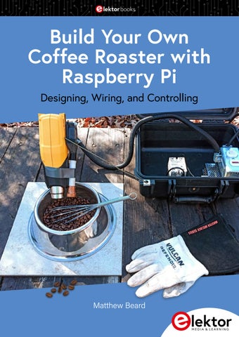
Build Your Own Coffee Roaster with Raspberry Pi Designing, Wiring, and Controlling
Matthew Beard
This document prepared COMPLETELY using opensource software in Linux Edition 1.2, 2025
If you don't have what you want, Try to create it. If it doesn't work the way you want it to, change it. And repeat.
Cyberhobbit Research & Development, 2026
● This is an Elektor Publication. Elektor is the media brand of Elektor International Media B.V.
PO Box 11, NL-6114-ZG Susteren, The Netherlands Phone: +31 46 4389444
● All rights reserved. No part of this book may be reproduced in any material form, including photocopying, or
storing in any medium by electronic means and whether or not transiently or incidentally to some other use of this publication, without the written permission of the copyright holder except in accordance with the provisions of the Copyright Designs and Patents Act 1988 or under the terms of a licence issued by the Copyright Licencing Agency Ltd., 90 Tottenham Court Road, London, England W1P 9HE. Applications for the copyright holder's permission to reproduce any part of the publication should be addressed to the publishers.
● Declaration
The author and publisher have made every effort to ensure the accuracy of the information contained in this book. They do not assume, or hereby disclaim, any liability to any party for any loss or damage caused by errors or omissions in this book, whether such errors or omissions result from negligence, accident, or any other cause. The author expresses his sincere gratitude to Arrow Electronics and Trenz Electronic for granting permission to include various tables, figures, and program codes in this book.
● I SBN 978-3-89576-711-1 eBook ● © Copyright 2026 Elektor International Media www.elektor.com
Editor: Glaucileine Vieira
Elektor is the world's leading source of essential technical information and electronics products for pro engineers, electronics designers, and the companies seeking to engage them. Each day, our international team develops and delivers high-quality content - via a variety of media channels (including magazines, video, digital media, and social media) in several languages - relating to electronics design and DIY electronics. www.elektormagazine.com
Contents Contents • Preface .......................................................................................... 5 • Preface ………………………………………………………………… • Building the Cobra Smart Roaster ............................................ 6 4. • The Powerhead ......................................................................... 8 • Building The Cobra Smartroaster……………………………………. 6. • The Power Supply .................................................................. 12 • The Heat Relay ....................................................................... 13 7. ◦ Powerhead construction……………………………………………. • The Raspberry Pi .................................................................... 14 11. ◦ Components ………………………………………………………… ◦ Low wiring ………………………………………………… • voltage Final Assembly ....................................................................... 16 16. ◦ •High voltage wiring ………………………………………………… The open Roaster Controller .................................................... 2218. • What ORC Does ..................................................................... 24 • The Open Roaster Controller ………………………………………… 22. • Installing ORC5 ...................................................................... 27 ◦ Installation ………………………………………………………… 26. • TheSetup ORC5……………………………………………………… Web Interface ....................................................... 33 31. ◦ Network • web The Tools Page………………………………………………… ........................................................................ 3632. ◦ ORC interface • Roasting Coffee with the Cobra ............................................... 38 • Roasting coffee with the Cobra • Method #1 Hand Stir in ……………………………………… a Bowl ............................................. 39 38. ◦ Handstir roasting ………………………………………………… 38. • Method #2 Repurpose a Bread Machine ............................... 44 ◦ Breadmachine roasting …………………………………………… 43. • Advanced Topics ........................................................................ 50 • Manual .......................................................................... • Advanced coffeeMode roasting topics ………………………………………5149. • Fixed Profiles .......................................................................... 5250. ◦ Manual mode ……………………………………………………… ◦ Fixed profiles ……………………………………………………… • Connecting ORC5 to Artisan Scope ....................................... 65 51. ◦ Connecting to ArtisanScope ……………………………………… • ORC System Programming .................................................... 69 64. ◦ ORC system programming ………………………………………… 68. • Parts List .................................................................................... 73 • Conclusion .................................................................................. 76 72. • Parts list ……………………………………………………………… • Questions, Answers, Ramblings .............................................. 77 • Conclusion ……………………………………………………………… • Helpful Websites and Further Reading ................................... 78 75. • Further reading ………………………………………………………… 77.
Hello, Friends. This document will walk you through building a simple coffee roaster, using various parts from online sources, hardware stores, and salvaged appliances. Despite the simple construction, the roaster can automatically follow roasting profiles, to roast your coffee exactly the way you want. You can buy small coffee roasters, of course. But they are expensive, and I would rather make something myself if I can. That way I can spread out the cost, and also have total control over what the machine does. Plus, if something I build breaks, I know I can always fix it. This machine, the “Cobra”, was built for around $120 USD and uses the same operating system I created for my larger coffee roaster. I call this system the OpenRoasterController, or ORC for short. It’s a Linuxbased program that runs within the NodeRed environment, more on that later. This software is free, with no subscription cost per month. I've formatted this as a complete operating system for the Raspberry Pi, with an easy setup method. And building the machine isn't difficult, as long as we are careful and don't get in a hurry. Follow me, I'll show you what to do.
*Pretarif prices. Cyberhobbit Research & Development is not liable for any emotional or bodily harm to person or property incurred from this information or software.
1.
Building the Cobra Smart Roaster
Early bronzeage coffee roasters, circa 10,000 B.C. (Artist rendition)
Building the Cobra Smart Roaster these printed. There are also online services that will print these files and mail them to you for an extra fee.
hen I developed the plans for this machine, my goals were to create the simplest and cheapest machine possible that would run ORC5 and roast coffee. If it wasn’t absolutely needed, It didn’t get included in the design.
These plans are written by a person living in the United States of America, so this is based on 120 V electrical service. If your local electrical voltage is different, you will have to source alternative parts that match your voltage!
For tools, you will need at least a cheap electric drill and some small drill bits, a soldering iron, some wire strippers, and some common hand tools like screwdrivers and pliers. A multimeter will also be required, as well as a way to cut some tubing. None of these tools are hard to find or expensive, and will be useful for other jobs anyway.
SAFETY As a father, this is where I would typically say, “Don’t cut yourself.” Also, don’t burn or electrocute yourself, don’t get glue in your eye, and don’t drill into the end of your finger.
There are no welding or other special tasks required, and this can easily be assembled at a kitchen table or whatever space you have. There are a couple of 3D printed plastic parts used, and if you don’t have a 3D printer, you could use local resources like a library or a makerspace to get
This project involves some 120 V wiring, and you will need about the same level of skill as it would take to repair a typical table lamp. Always make sure that your cord is unplugged while you are working on any of the wiring, high or low voltage! 6
●7
And don’t make any connections to the Raspberry Pi GPIO pins with the power on, anyway.
The whole package is housed in a sturdy plastic case, which makes transport and storage easy. I used an Apache 2800 case from HarborFreight which is a knockoff of the nicer Pelican case, but it’s perfectly fine for this project. I drilled holes in the case for mounting components, since I wasn’t concerned about maintaining any watertightness. It will still keep dust and dirt out. If you would rather use some other container, feel free to change this.
Most importantly, don’t get in a hurry. Take your time, and think about what you are doing. If it’s something you haven’t done before, watch some videos first. Building things yourself is deeply rewarding, but nobody likes getting hurt. Know where a first aid kit is, just to be on the safe side.
The Powerhead This project uses a cheap heat gun as the heat source; the one I used was a Wagner Furno 300. You can use something more expensive if you want, but be careful not to choose an “electronic” heat gun with buttons for selecting different heat settings, as these won’t work right with the heat relay. Nope, you want a “dumb” heat gun with just off, low, and high. The switch will be left on high, and the control system will give us zero to 100% heat adjustment.
The Cobra Smart Roaster folded in its carrying case ●8
7
sensor lens will still develop a film of coffee oil during use, clean it when needed with a soft cloth. 3D print the blower mount. This file is located at www.thingiverse.com/ thing:6803226. I printed this in PLA plastic at 100% infill, but ABS would be better for heat resistance.
The Cobra powerhead
It is designed for the 50x15mm blower to bolt to, and directs the air down the sensor tube. The sensor tube is a 3.5" length of 1/2" PEX tubing from the plumbing section of your local hardware store, and it should fit snugly into the blower mount.
The infrared sensor assembly gets added to the side of the heat gun. This is made using a small 3D printed housing to connect the blower to the sensor tube and fitting that holds the actual infrared sensor. The purpose of the blower is to continuously blow a low volume of air over and around the IR sensor. This is to both keep it cool, and to keep steam, smoke and chaff away from the sensor lens. It works fairly well, but the
MLX 90614 The infrared sensor itself is an MLX90614 mounted on a small PCB. This sensor will read up to 700 degrees fahrenheit (370 C).
3D Printed Blower Mount 8
●9
However, I found the wires to be a bit difficult to solder, and I also found out that typical ethernet cable has no tolerance whatsoever for high temperatures. On the second build I cut the cords off of a few cheap cordless phone power supplies, these were easier to work with, although the wires were all black.
The sensor uses four wires: 5 volts, ground, SCL, and SDA. You need to solder four wires to this PCB before it gets glued to the copper fitting.
No matter what wires you choose, take careful notes and label things so that you know what wire goes to what location on the PCB. After soldering, the four wires from the sensor PCB will run through the copper fitting and down the sensor tube.
Infrared sensor glued into copper fitting These need to be fairly small gauge and at least a foot longer than the heat gun’s power cord. Full disclosure, I’ve built this part of the project twice, since I might have completely melted down the first powerhead prototype during some early, uh, destructive limit testing. On the first build I used a secondhand common ethernet cable for this job, since these have eight wires which all have a unique color. We need six, the blower also needs power and ground.
● 10
Fitting trimmed The copper fitting is a 3/4" by 1/2" reducer adapter. The tube is trimmed so that the sensor doesn’t “see” the edge of the copper tube. Don't glue the copper fitting to the PEX tube, this will let you take the sensor apart later if you need to. 9
The Completed Infrared Sensor Unit Don’t substitute plastic for the copper fitting, it’s exposed to a large amount of heat. The Infrared sensor PCB is glued into the copper adapter with E6000 glue, this glue can be found in any hardware store and is useful for many purposes. It’s very smelly, make sure you have some ventilation. Glue the sensor into place and make sure that it stays even and flat in the tube, not crooked. Let it dry for at least 24 hours. The blower will have a short power cable. You can connect wires to this, but I removed the existing wires and just soldered longer wires into place. Make sure you know which wire is positive and negative. If everything is prepared, run the sensor wires through the blower tube and the blower mount. Bolt 10
the blower into place with two 4 mm × 30 mm bolts. Run a zip tie through the extra hole in the blower mount to secure the wires and hold the sensor together. There, your custom infrared airflow shielded heat sensor is complete. Neat, right? You can’t buy one anywhere... I mounted the sensor unit to the heat gun by using an epoxy putty made by J-B Weld. This will be permanent, so be sure about this before you commit. If you need to replace the heat gun later, you will probably have to cut a new PEX tube and rewire the sensor. I tried just using tape for simplicity, but the heat will always make the adhesive fail at an inopportune time.
● 11
On the Wagner heat gun, the tapered side of the gun naturally meant that the focus range of the heat sensor would overlap with the heat field the gun creates, a few inches in front of the barrel. This is important, so if you use a different heat gun make sure to “aim” the sensor to create this effect.
The Power Supply We need to supply our equipment with a dedicated power source. I chose a 5 V, 5 A unit, which provides more than enough current (the Pi requires at least 2.5 A). The Pi, the infrared sensor, and the sensor blower all operate on 5 V.
5 V Power Supply Infrared sensor view should overlap heated area Use some 1/2" automotive split wire loom to hold the sensor wires and the heat gun power cable together, some zipties should help keep this in place. This creates a flexible, intentional looking umbilical cable.
● 12
Before mounting anything, hook up a power cord to the power supply AC terminals. This is our first opportunity to practice our electrical safety. It’s easy, and nobody is going to get electrocuted, because we are
11
Electrical Connections for Setting the Power Supply Sticking with this habit will keep you safe while working on this project or that old vacuum cleaner with the bad switch. Ok, safety rant over. Round up a mediumduty replacement power tool cord or something similar, a 14gauge cord rated for at least 15 amps will be fine. Connect this to the power supply, black is the (L) line and white is (N) neutral. Since AC electricity alternates it will technically work backwards, but we’re gonna do it right. Green is ground. Plug the cord in, and the green LED on the power supply should light up. Carefully use that multimeter to check the voltage at the low voltage terminals. It should be 5 volts or close to it. 12
Mine was off a bit, use the adjustment screw to set it to exactly 5 volts, and unplug the cord.
The Heat Relay The solidstate relay that we will use for this project is one of those affordable modern marvels of technology that we have the luxury of being able to use. This device will allow a lowvoltage directcurrent signal from the Pi ito switch a massive alternatingcurrent load, multiple times per second.
● 13
The heat sink should come with a tube of the heat transfer paste, use it all in an even layer. The excess will squeeze out when the screws are tightened.
The Raspberry Pi
SolidState Relay As a bonus, these relays are optocouplers which means the Pi is actually just lighting up an LED to trigger the relay. Because of this, the signal is isolated and we won’t get any weird circuit feedback.
This project is based on a Raspberry Pi 3B. At the time of this writing, the most recent Pi is the model 5. However, for what we are doing, the 3B is more than enough in terms of computing power, and they are cheap at $35 bucks or so. There’s nothing wrong with using a higher powered unit though. I wouldn’t use an older Pi or a Zero for this, due to speed and memory.
These relays require a heat sink with heat transfer paste in between the heat sink and the relay. This is critical, don’t leave this out or the relay will overheat.
Relay with HeatSink ● 14
Raspberry Pi 3B in case 13
Arrangement of Parts Print or order a plastic case for the Pi, this will protect the Pi and give us a good way to mount it into our larger case. I printed mine using this design: www.thingiverse.com/ thing:922740
My only complaint with how this worked out is that the memory card is on the bottom and is nearly impossible to get to once this is bolted down. However, it’s not something that you need to access very often either.
Bolting It All Down I won’t give you exact dimensions for where to mount the components, the spacing isn’t critical. Arrange things generally as shown, so that the heat gun, heat relay and power supply nest together.
Pi mounted at front of case 14
● 15
The power switch is mounted to the side of the case and is above but not touching the power supply (We will get to that shortly). Mark where to drill your holes for mounting these parts. Mount the Pi case on the front wall of the enclosure, near the handle. Leave enough room to access the USB ports for connecting a keyboard and mouse later. There is a round pressure release knob on the front of the Apache case, this got in the way so I removed it. I used small wood screws that were short enough to not penetrate to the outside of the case. It’s only necessary to use the two top screws, since you have to take these out to access the SD card.
Final Assembly It’s time to bring this all together. The lowvoltage connections are shown on the next page. Follow the schematic for the infrared sensor (and the blower), the input for the solid state relay, and the power feed for the Pi. Red is +5 volts and black is negative or ground.
● 16
15
Typical USB Wiring
I used an old microusb cable for the Pi’s power input, make very sure you are getting the + and connections correct here. For the USB power cable only connect the red and black wires, the green and white are data wires, which we don’t need. The “SCL” and “SDA” terminal of the infrared sensor connect to the SCL and SDA pins of the Pi. The GPIO (General PurposeInputOutput) pins are where the magic really happens for the Pi. There are plenty of projects that involve turning the Pi into media players, video game emulators, etc. But it’s when you connect this little wonder to other actual pieces of hardware that things really get interesting…
books books
Build Your Own Coffee Roaster with Raspberry Pi Designing, Wiring, and Controlling
Build Your Own Coffee Roaster is a practical guide to constructing and operating the Cobra Smartroaster and its companion Open Roaster Controller (ORC). The book walks the reader through every stage of the build, from assembling the powerhead and wiring the system to installing and configuring the controller. Along the way, you’ll learn how to use the Raspberry Pi to bring precision and flexibility to your roasting process.
Matthew Beard has spent over twenty years in maintenance and process engineering, in the automotive, marine, bio-medical and specialty coffee industries. He prefers stick shifts, Linux, and anaerobic fermented coffee, preferably simultaneously.
Clear, step-by-step chapters cover:
> Powerhead construction and required components > Low- and high-voltage wiring > Installing the ORC, network setup, and using the web interface > Roasting coffee with the Cobra in different setups, including hand-stir and bread-machine roasting
> Advanced topics such as manual mode, fixed profiles, Artisan-Scope connections, and ORC system programming
A complete parts list, practical guidance throughout, and concise explanations make this book a useful reference for anyone interested in building, modifying, or understanding their own coffee-roasting system.
Elektor International Media www.elektor.com