14 minute read
Pierre-Yves Piece. Salt Rake found at Nantwich, Cheshire

from Saltcote 2019 No.7
by Ecosal-uk
Salt Rake Found on Banks of River Weaver, Nantwich, Cheshire
Kerr , Nantwich Museum
Advertisement
Sasha, Archaeologist Extraordinaire, finds ancient salt making tool
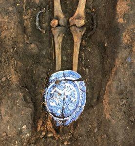
Whilst being exercised after the recent flood near the Fairfax Bridge over the River Weaver in Nantwich, Sasha, a rescue dog belonging to the Shepherd family, unearthed a fragment of decayed wood. Close inspection revealed that the crescent shaped wood had a tapered blade, a hole in the centre and had clearly been made by man.
Sasha’s minder, Dave Shepherd, was alert to the origins of the find and in discussion with local historian Andrew Lamberton determined the fragment was part of a rake once used to remove salt from the pans in which brine was being evaporated.
The rake head was probably liberated as the flooding river washed away the remains of a former wich or saltmaking house. The salt-making industry was at its height during Tudor times so the rake head could be more than 500 years old.
The rake head was transferred to Nantwich Museum where it will be conserved to eventually be displayed as part of the story of salt making in the town.
Sasha’s contribution in finding the artefact will not be forgotten.

Rake head found on the banks of the River Weaver, Nantwich.
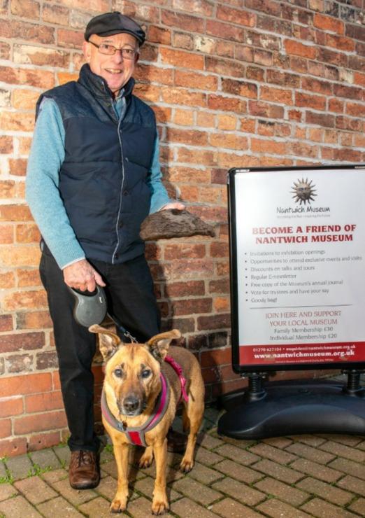

Dave Shepherd and Sasha. Photo: Nantwich Museum.
Robina McNeil, Two 12 th century wych houses in Nantwich, Cheshire. Med. Arch. 1987. Vol 27, pp40-80.
RESTORATION - Lion Salt Works Brine Pump, Marston, Northwich

Kate Harland, Senior Learning and Operations Officer, Cheshire West and Chester Council
Juan Cunliffe, spoke about his research into the Lion Salt Works brine pump at the salt conference organised by the Newcomen Society in 2018 and reported in Saltcote No.6. Restoration of the equipment erected in 1938 described by Juan has now been completed by Cheshire West and Chester and this report is edited by Andrew Fielding from display material provided by Kate Harland and Magnus Theobald.
The horizontal steam engine was the second to be installed at the site. The first was located beneath the brine tank at the north of of the site, beside the canal. The horizontal

pumping engine no longer survives but in an 1899 inventory was described as being by Craven Brothers of Manchester with a 14 inch diameter cylinder and a 28 inch stroke. The horizontal boiler still survives. It was made by Galloway & Sons and has two furnaces. The first headstock erected over a hand dug brine shaft (8 ft square and 46 yards deep,well timbered and puddled, with two sets of pump trees pumps), though still standing when the works closed in 1986, was in very poor condition and collapsed before being cleared away. The new brine borehole had to be located on land where the Thompsons had rights to wild brine pumping.

The brine tank and lattice tower date to 1894. The tank is 33ft x 22ft x 7ft and held 30,000 gallons of brine. The lattice tower is over the original brine shaft.
Lion Salt Works layout c 1900 showing four common salt/ fishery pans on the Thompsons’ land owning brine pumping rights. Shed erected to display the engine to visitors in 1980’s
Re-purposed chimney
Schematic drawing by Mike Jones

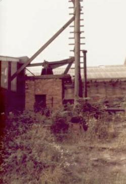
The 1938 brine borehole and nodding donkey engine (above) as found in 1989. It was built on the then derelict common salt / fishery pan No.3. The two legs of the derrick were constructed from parts of a mast, possibly the Thompson’s barge Nautilus. The steam winch used to haul coal wagons to the works on the mineral line also came from the Nautilus.
The schematic drawing (left) shows the engine, derrick and pump location on the remains of common pan No.3. The boiler house to the left was connected to the former chimney of common pans No.3 and No.4 by an underground flue.
Engine schematic

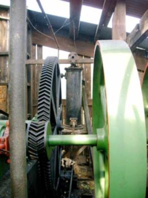
The Lion Salt Works steam engine has no manufacturer’s nameplate but has commonly been referred to as the ‘Marcus Allen’ engine due to a ‘marked up’ archive drawing dated 1910. It was installed in its present location in February 1938. It has a single ‘double acting’ cylinder and an eccentric cam operated slide-valve which controls the admission of steam to, and the exhaust of steam from, the cylinder. The piston drives the output shaft through a connecting rod and crank. The output shaft has a 23 tooth pinion and a fly wheel to smooth out speed fluctuations during every cycle. The 23 tooth pinion meshes with a 139 tooth pinion, which is mounted on the gearbox output shaft crank and is linked to the input arm of the nodding donkey. The gearbox output crank has a stroke of 42 inches and operated at between 10 and 14 revolutions per minute.
The gear teeth are cut in the form of a double helix (herringbone) so that no axial thrust is transmitted to the shafts carrying the gear wheels. The gearbox was manufactured in 1937 by Ormerod, Grierson and Co. Ltd of Radcliffe, Manchester.
A centrifugal governor controls the speed of the steam engine via the inlet steam valve.
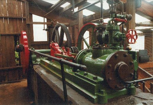
The connecting arm passes through the north wall of the engine house linking the output crank to the nodding donkey.

Gearing for ‘Brine Pump’ for Messrs Ingram Thompson & Sons, Lion Salt Works, Marston. Oct: 25/37

The Cornish type boiler was made by William Lord of Bury and is dated 1891, so was 47 years old when installed by the Thompsons for use at the Lion Salt Works. It is located in a small building attached to the side of the Manager’s office. The pipe work on the boiler front brought hot, high pressure, feed water delivered by a Cameron pump, the feed water having been warmed by exhaust steam within the engine house. The operating steam pressure of the boiler was in the range of 80-100lbs per sq inch.
The steam raised was used to power the “Marcus Allen” steam engine and the Cameron feed pump, a steam winch as well as a second engine driving a circular saw and a guillotine and punch in the Smithy. And a third engine drove a crushing mill in No.2 Warehouse.


HEAT EXCHANGER
A heat exchanger was installed to improve the thermal efficiency of the steam engine. Exhaust steam from the engine was piped through the body of a heat exchanger and cold feed water from the header tank was passed through a tube coiled within the body of the heat exchanger. The feed water became heated by the hot exhaust steam and was then piped to the boiler feed pump.
BOILER FEED PUMP
To pump water into the boiler working under steam, the boiler feed pump was required to deliver it at a pressure above the boiler operating pressure. A compact, single cylinder, vertical boiler feed pump, manufactured by John Cameron of Manchester, is installed beside the steam engine foundation block. The steam cylinder at the top drives the pump at the base as both are connected to a ‘banjo’ casting. To improve the smoothness of the pump delivery a heavy flywheel is linked to the ‘banjo’ casting by a short connecting rod and crank, which rotates within the empty space in the centre of the casting.


ELECTRIC MOTOR DRIVE
In August 1960 the electricity supply to the Lion Salt Works was reinforced by the installation of a dedicated pole mounted transformer. In 1962/3 the steam power was replaced by a 15hp 1450 rpm electric motor and double reduction vee belt system. The final vee belt pulley was mounted on a new extended steam engine output shaft.
Following the sinking of a new borehole in the north east corner of the site in 1964 and the installation of an electric submersible pump in 1965, the brine supply to the Lion Salt Works was no longer reliant on the ‘Marcus Allen’ engine and the nodding donkey. The pump rods were removed from the rising main but the electric motor continued to turn over the engine gears and the nodding donkey to entertain
visitors until the works closed in 1986.
Electric submersible pump. The last brine pump to operate at the Lion Salt Works.
In 1937 Samuel Timmins and Sons drilled a borehole 47 yards to the wet rock head. A pump and the 6 ½ inch diameter, 130 ft long rising main were suspended from the borehole top plate. Alan Thompson recorded in his diary that the new borehole commenced pumping at 11.55am on 12 April,1938. The pump was manufactured by WJ Yarwood & Sons, a Northwich firm that specialised in shipbuilding and engineering. At a typical steam-engine output crank speed of 13 revolutions per minute the brine pump output was 2,800 gallons per hour. The brine tank could hold 30,000 gallons. It is set up at a higher level than the salt pans so brine flows to them by gravity.
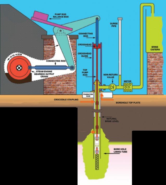
When the pump piston descends the foot clack valve closes and the entrapped brine flows through the open piston clack valve. When the piston rises the piston clack valve closes and brine is drawn into the pump barrel through the open foot clack valve. The column of brine above the piston is lifted and pumped towards the brine cistern. Weights in the pump rod balance box are equal to the weight of the pump rods and the column of brine in the rising main
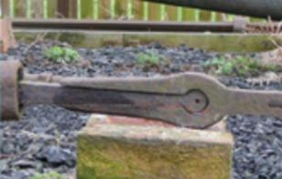
A string of pump rods connect the output arm of the nodding donkey to the brine pump. The pump rod end couplings are designed to be secured by a loose ring when joined and be easy to connect and disconnect. To lift the pump out of the borehole the string of rods is raised and clamped to enable the uppermost rod to be disconnected. This procedure is repeated until the pump has been removed from the borehole. The pump rods have crocodile couplings and are typically nine yards long. At least five rods would been used to drive the brine pump.
No brine will be pumped physically to the surface but instead will be capped with a blanked off stainless steel sleeve just below ground level to give the illusion of brine being extracted.
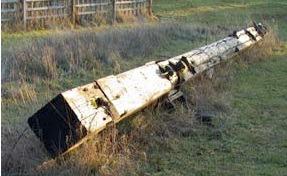
A permanent guyed bi-pod derrick was positioned above the borehole and the hand winch was used to raise and lower the pump rods for maintenance. The Thompsons’ use of second hand materials has led to the rare survival of a mast from a Weaver barge Nautilus used to make the derrick.
Piston clack valve.

Piston foot valve.
Hand winch used to lift pump rods out of the borehole using the derrick.

Borehole top plate and attached discharge fitting with pipe branch to the brine tank

Meter recording the quantity of brine extracted from the borehole.
CROSSCANONBY SALT PANS: Allonby Bay, Cumbria
Andrew Fielding: Ecosal-UK
A small research grant has been awarded to Ecosal-UK by the Association for Industrial Archaeology to re-evaluate the salt making site at Crosscanonby, Cumbria in the light of the newly exposed features. The site is well known and part of it is a protected scheduled monument and is within the Solway Coast Area of Outstanding Natural Beauty. However, the newly exposed elements are not within the protected area and are vulnerable to further erosion, as is the whole coast in this area. Our work will reinforce the need to adequately maintain the gabions inserted to protect the main site from erosion.
There have been two investigations of the site. The first was an excavation in 1985-6 by KE Bowmer and Deborah Walsh and the second, in 1995, by Dr Paul Collins, Wendy Horton and Michael Worthington by the Ironbridge Institute for Allerdale Borough Council. This was published as Ironbridge Institute Research Report No.97. The Ironbridge report identified the site as having been operated by the Lamplugh family and not the Senhouse family, though many web sites still attribute the site erroneously to the Senhouses.
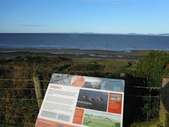
Looking down on the salt works site from Swarthy Hill, with interpretation board.
Part of our work will be to correct existing on-line descriptions and re-evaluate the site in the light of the newly uncovered structures. The salt making site at Crosscanonby, Cumbria was visited in 2012 by the UK’s Ecosal-Atlantis team.
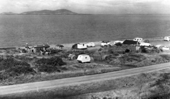
Post Card showing the site when it was used as a caravan park.
The 'well' structure and associated pipe seen then are now fully covered by sand, but two other structures previously covered over by sand have been uncovered.
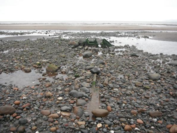
The furthest feature may be a similar structure to the 'well', though only three posts seem to survive rather than four. It is 90m further out to sea from the end of a newly exposed wooden pipe, and 118m from the gabions that protecting the salt works.
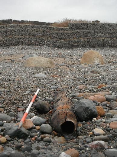
The newly exposed wooden pipe has a 4 inch bore within a 10 inch outer diameter trunk. Two areas of corrosion suggest iron banding, which has preserved original tree bark. The salt works was constructed in 1634. A lease of 1649 for Francis Barwise describes - 'two salt pans, water sumps, swath and all singular other the appurtenances thereunto belonging and appertaining..’, which may refer to the pipes running under the beach.
A Video record of the pipe was made and is uploaded to YouTube. It shows the wooden pipe freshly exposed in the inter-tidal zone below the salt works site. See video - https://youtu.be/SN92i_cePTk
AIA e-news Bulletin July 2020
AIA Research Grants https://industrialarchaeology.org/aia-awards/research-grants/
Wooden pipe exposed by storm and high tide on 13 March 2020.
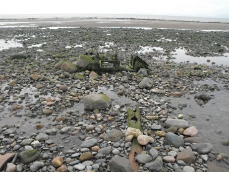
March 2012 - The ‘well’ structure and pipe when visited as part of the Ecosal Atlantis project.
October 2019 - The ‘well’ structure and pipe when visited by Ecosal-UK. The associated pipe has suffered from erosion compared to 2012.

December 2019 - The same ‘well’ structure when visited as part of a weekly monitoring of the site by Ecosal-UK. By January 2020 it was fully covered by sand.

The ‘well’ structure visited for a second time as part of the Ecosal-Atlantis project in October, 2012. Human scale provided by Katia Hueso Kortekaas, Co-Director of IPAISAL, Spain. https://ipaisal.blogspot.com/ The value of being able to visit coastal areas on a daily basis is that the subtle, and sometimes dramatic, changes to the inter-tidal area can be monitored. Sand can be moved about over a wide area between tides, and in dry and calm periods wind blown sand can move in huge quantities to build up the dune areas. Storms and gales can inflict different degrees of damage depending on the wind direction, the air pressure and whether the storm impacts during a spring or neap tidal range.
Our photographs of the main ‘well’ structure show that degree of exposure that the feature experienced over a seven year period, between 2012 and 2019, and showed that it can also be covered completely by sand within a two month period - Oct to Dec 2019.
An interpretation of the timber structure as a base for a ‘tower’ structure to carry sea water to the salt works was based on a survey carried out in 1995.
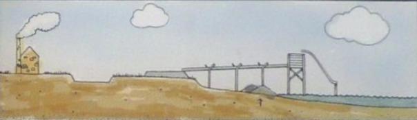

A re-interpretation of the ‘well’ structure suggesting it was part of an underground ‘sump’ for carrying sea water to the salt pans in a pipe beneath the sand. The eroded sand level is shown in yellow. This places the seventeenth century beach over 100 meters away from the working salt pans.

Proposed schematic of the ‘well’ structure suggesting it was an inspection point for a pipe carrying sea water beneath the sand from the foreshore to the salt works.