Single anterior immediate implant to replace a non restorable lateral incisor with a GEN5

Introduction
In today’s modern dental era, patients and clinicians want to decrease appointments, restore esthetics and function efficiently, and minimize complications. Placing implants into fresh extraction sockets and bone grafting the gap has been shown to preserve hard and soft tissue resulting in a natural appearance with the final abutment and restoration4 Implementing digital technology increases the comfort to the patient, decreases treatment time, adds to the predictability of the outcome and reduces stress to the operating surgeon.
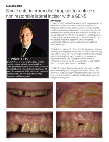
JB White, DDS
Dentist. Areas of focus: Implantology, esthetic dentistry, digital technology and work ows. Graduate of the University of Missouri-Kansas City School of Dentistry. Private Practice Las Vegas, 19 years. Founder of the White Institute and owner of Sunset Dental Lab. Post graduate educator, innovator, and academician.
The following case report describes the diagnosis, treatment planning, and surgery of a fractured, non restorable maxillary right lateral incisor. The report begins after the initial disease control aspects of the patients treatment through the implant procedure. The future plan for the patient is orthodontics and full mouth reconstruction to address the attrition, erosion, occlusion and aesthetics.
The GEN5 implant (Paragon, Las Vegas, Nevada) is a fifth generation design with an aggressive thread pattern, two millimeter anodized, machined collar that is ideal for both fresh extraction sockets and healed ridges in the anterior and posterior regions.
Initial presentation:
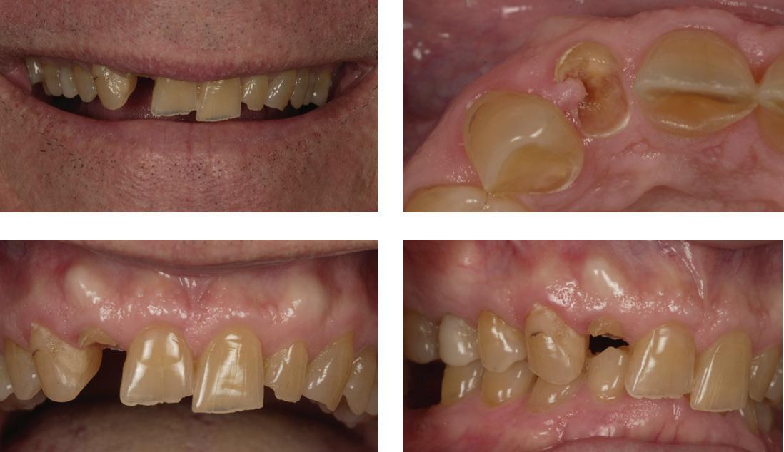
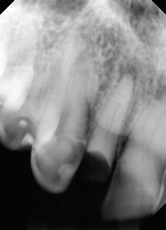
A healthy 67 year old male presents with a fractured, non-restorable lateral incisor with a chief complaint of replacing the broken tooth (Figures 1 and 2). Patient has a pathological occlusion with pathway wear, a deep bite with 110% overbite, a lack of interocclusal space and retroclined maxillary incisors. A radiograph shows a peri-apical radiolucency (Figure 11). An intraolral examination reveals adequate keratinized gingiva around the lateral incisors site and good overall oral hygiene (Figures 3 and 4).
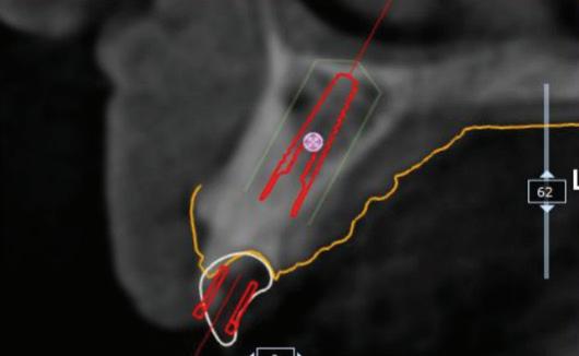
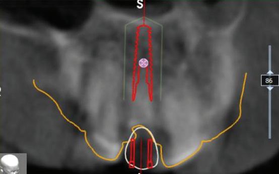
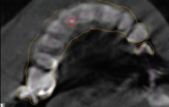
The evaluation with a Cone Beam Computed Tomography (CBCT) shows adequate cortical plate and trabecular bone to the palatal aspect of the root to be extracted (Figure 5). The lateral incisors is in a class 1 sagittal root position1. The available bone to achieve primary stability, and placing the platform adjacent to palatal wall, will result in a screw access channel exiting the facial aspect of the restoration. The screw retained final restoration will later be diverted to the cingulum area with an angled- screw channel abutment (Figures 8-10).
Treatment Planning
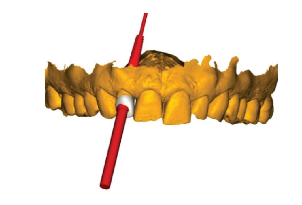
The implant was treatment planned to have the most coronal aspect of the platform 3mm below the facial gingival margin2 (Figure 5). To achieve primary stability and obtain enough threads into virgin trabecular bone and not perforate the nasal floor, a 14mm length was chosen. To achieve adequate distance between the platform of the GEN5 and the adjacent teeth, a 3.3mm diameter implant was planned (Figure 7).
Surgical Procedure
The day of the procedure, the patient was anesthetized with 4% Septocaine and the lateral incisor was atraumatically extracted. A 15 blade was used to incise the soft tissue attachment to the root and no flap was utilized as to preserve blood supply to the buccal plate (Figure 14). A spade style elevator (XO-70, X-Otome, A. Titan) was used on both the distal and mesial aspect of the root to obtain mobility and slight expansion of the socket.
Forceps (Plus Series, 150+ upper universal) were placed as far apically on the root as possible and apical force was applied with a slight rotation and the root was gently twisted clockwise and counter-clockwise as the forceps transitions to a coronal force. The root was gently removed without damaging the hard or soft tissue (Figures 12 and 13).
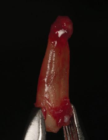
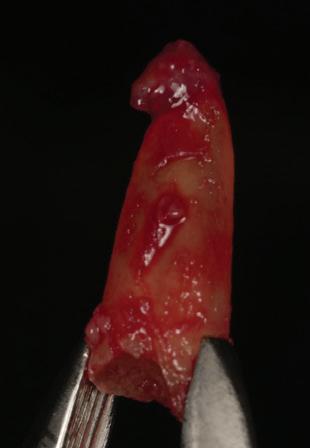
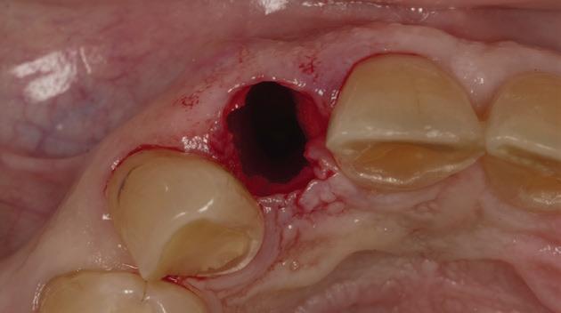
The root was observed to have a soft-tissue bundle attached to the apex upon removal. Two different curettes were used to enter the extraction socket to ensure no soft-tissue remained in the socket and to evaluate the buccal plate integrity and all bony walls. The socket was well intact in all dimensions and facial bone position was 3mm apical to the facial gingival margin3 (Figure 17)
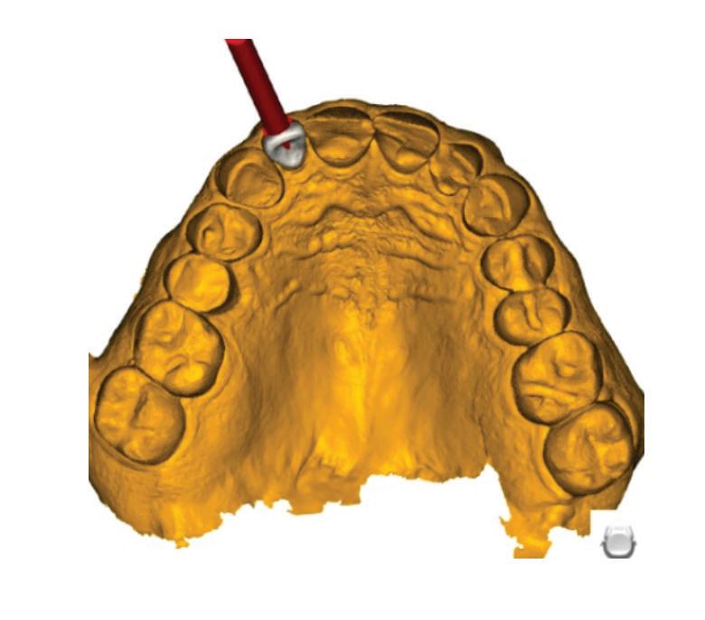
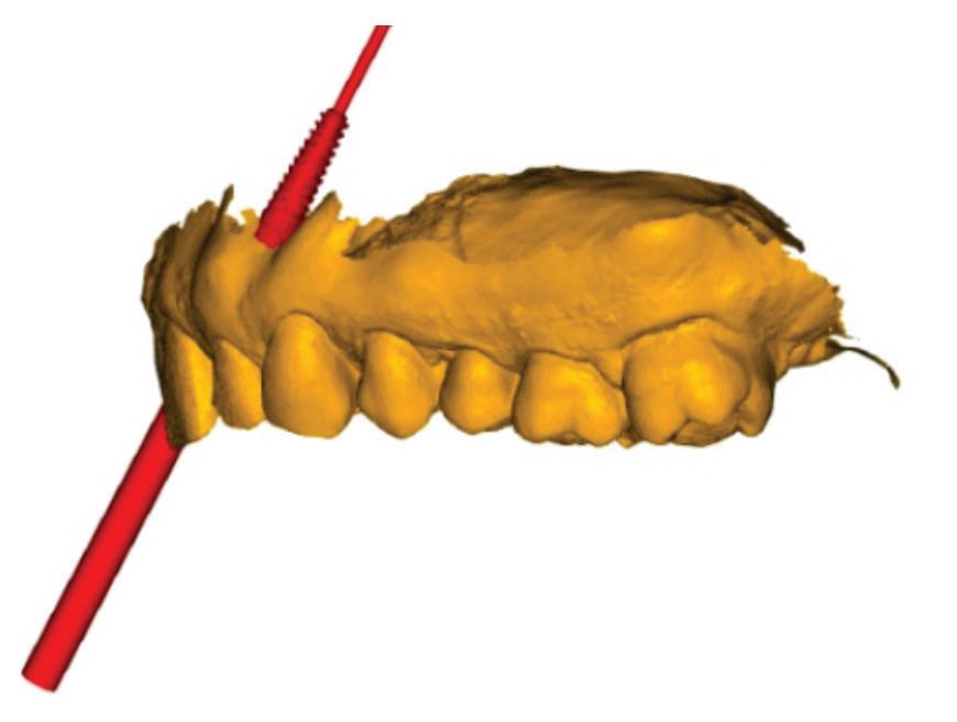
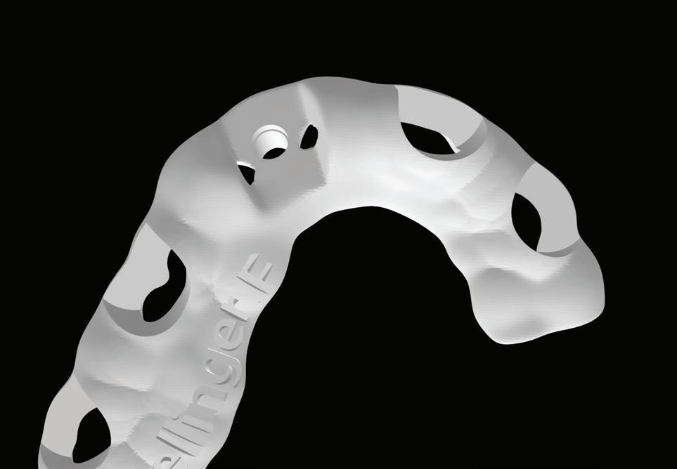
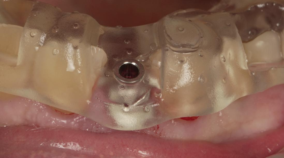
A 3D printed, tooth borne, surgical guide was designed by Implant Concierge (San Antonio, TX) by layering an intra-oral scan (Aoral Elite, Shining3D) over a CBCT scan (i-CAT) and printed on an F1 (Shining3D) printer (Figure 15). Surgical guides should always be evaluated for fit and accuracy with a complete seat with no rocking and evaluated through the cutout windows. In immediate scenarios, the guide can typically only be seated and evaluated after the extraction. In this case, even with the remaining tooth fragment being sub-gingival, it still prevented the guide from seating (Figure 16).
The osteotomy drilling sequence consisted of one drill, a 2.0/2.3mm size drill to 1mm coronal to the final apical position of the implant. The implant motor was set to 1200 rpm’s and the drill protocol consisted of an incremental drilling sequence never to exceed two millimeters without exiting the guide sleeve and allowing the saline to cool the tip of the drill and flush the threads clean. Caution was utilized at the start of the osteotomy to ensure the dense palatal bone was not causing the drill to run or lift the surgical guide off of the teeth. The drill depth was 25mm from the sleeve to final osteotomy depth.
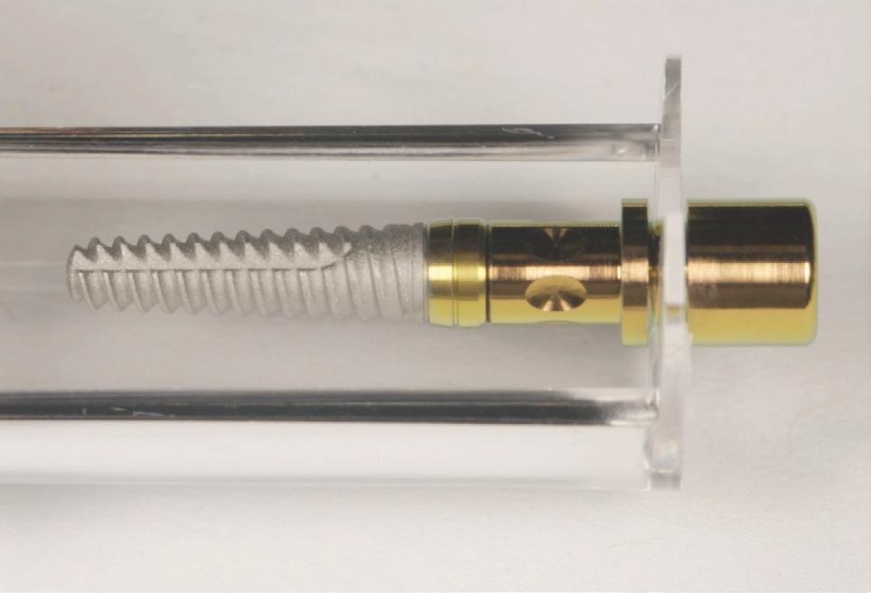
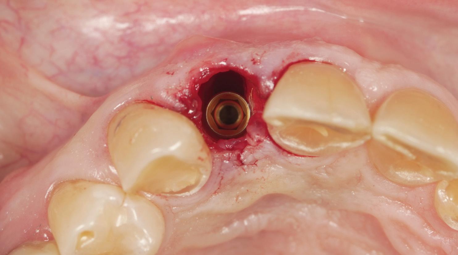
The GEN5 implant was removed from its sterile housing and initiated into the osteotomy by hand utilizing the carrier (Figure 17). After threading into the osteotomy and achieving stability, the carrier was removed by a coronal pulling motion. A bar type torque wrench was used with a 2.5mm insertion hex tool to torque the implant to final depth. A torque value of 35Ncm was achieved (Figure 18).
Prosthetic Procedure
One key aspect to the pink esthetic score architecture is to preserve the current facial gingival margin position and the inter-proximal papilla. This can be achieved by either a screw retained provisional or a custom healing abutment4. Both would have the same sub-gingival emergence profile. Due to the patient’s occlusion, inter-occlusal space and bruxism, it was decided to take a conservative approach, and utilize a custom healing abutment in this case (Figures 19 and 20).
A stock PEEK abutment was coated with adhesive (SE Bond), cured, and screwed into the implant and hand tightened. Flowable composite resin was “dragged” from the abutment to the gingiva in increments and cured to create a prosthetic socket sealing device. The custom abutment is used to hold the bone graft material and blood clot in place and prevent the soft tissue from collapsing5
It is common to try the abutment on the implant several times and modify the contour to have slight pressure on the tissue, but no blanching. It is best to error on under-contouring at this stage rather than blocking out the papilla or pushing the facial gingival margin apically. Once the desired contour is achieved, the gap between the implant and the buccal plate can be managed.
Mineralized cancellous bone is hydrated with saline or steriled water in a sterilized surgical bowl for 10-15 minutes prior to taking into the extraction socket. The bone is placed into the gap in small increments and pushed as far apically as possible adapting the material around the apex of the implant. Small increments are continually added and backfilled and the key is to not stop placing bone once you have reached the platform of the implant. The platform of the implant is 3mm below the facial gingival margin and bone material should be placed all the way to the top of the facial gingiva (Figure 21).
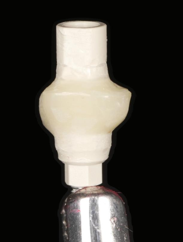
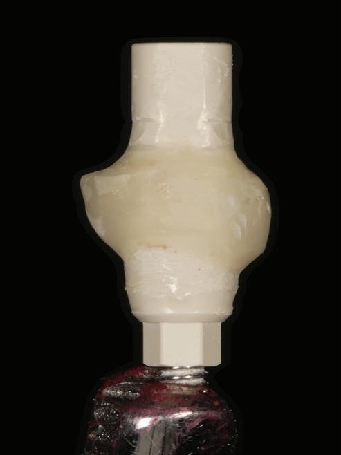
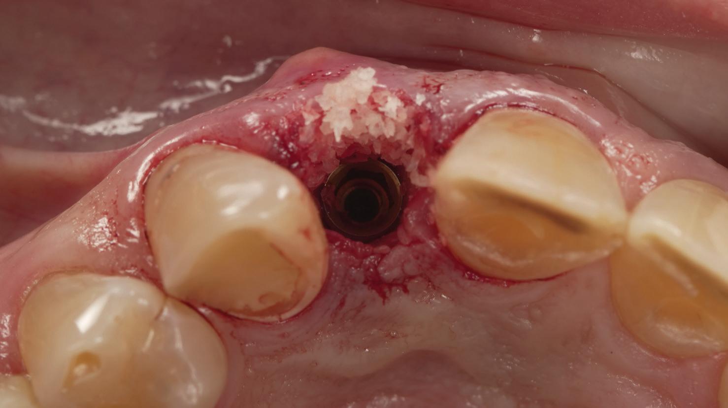
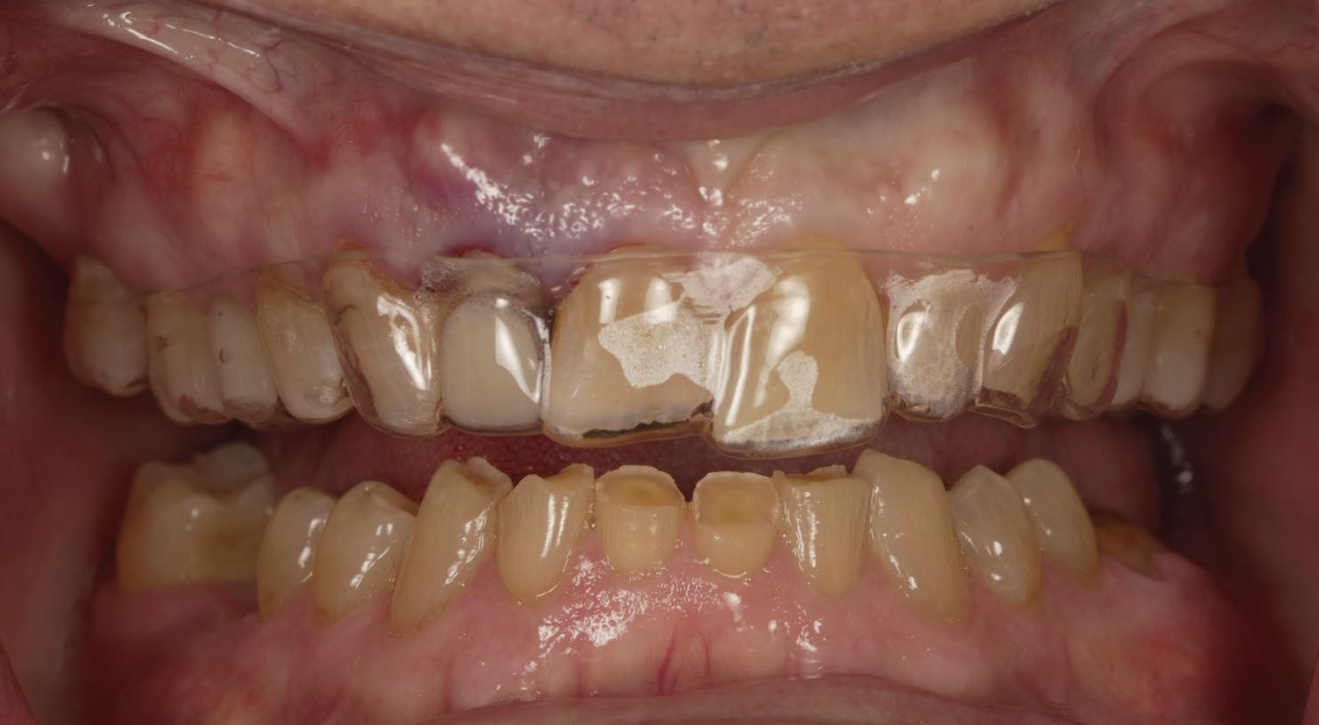
Fig. 20
This is referred to as the dual zone bone graft6. The bone zone, is from the platform of the implant apically and from the platform of the implant to the gingival margin is the tissue zone. Both the bone and tissue zones are grafted with particulate.
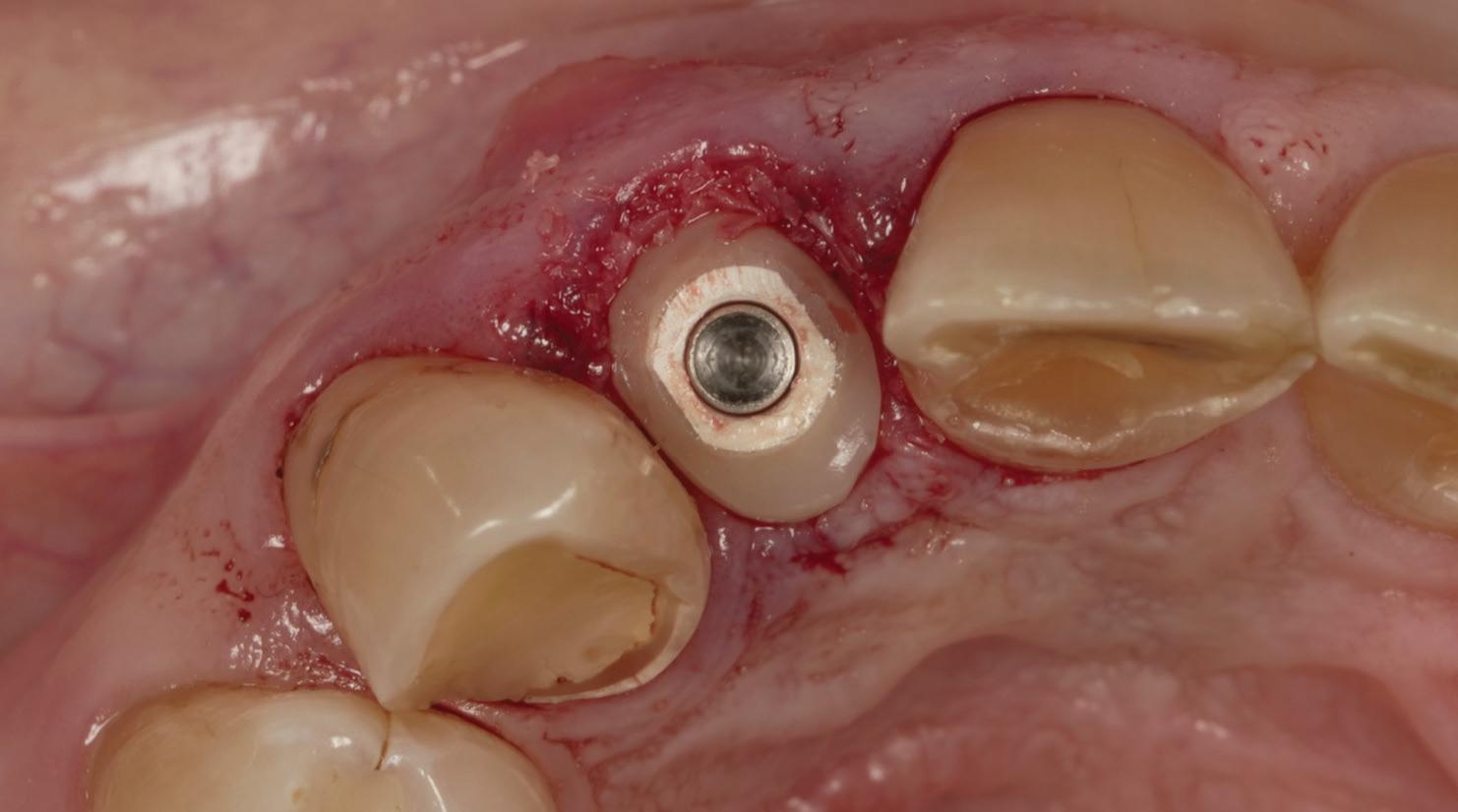
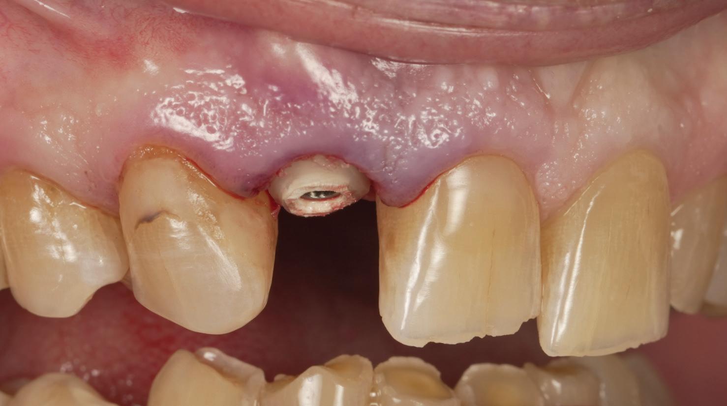
After the bone graft particulate has been filled and adapted, the socket seal (PEEK abutment) is placed on the implant platform and hand tightened into place, approximately 15Ncm. The chimney will then be trimmed down to the height of the abutment screw (Figures 22 and 23).
From the original intra-oral scan a lateral incisor was digitally designed and a model was printed on the F1 (Shining3D). Using a Mini-Star machine, a 1mm essix thermal-forming material is heated and adapted to the model. The lateral incisor is air-abraded on the intaglio with aluminum-oxide, adhesive is placed and cured, and flowable composite adapted.
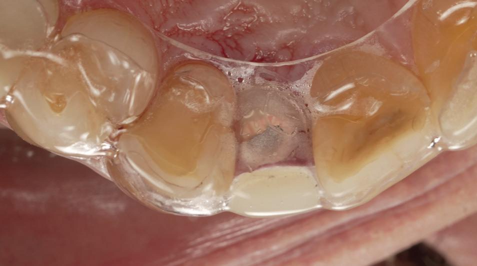
The essix appliance is tried in and evaluated for esthetics, occlusion and to ensure no pressure is being applied to the PEEK abutment or surrounding soft tissue (Figures 24 and 25). Tooth supported essix appliances are preferred over transitional partial dentures because of convenience and the ability to control pressure on soft tissue.
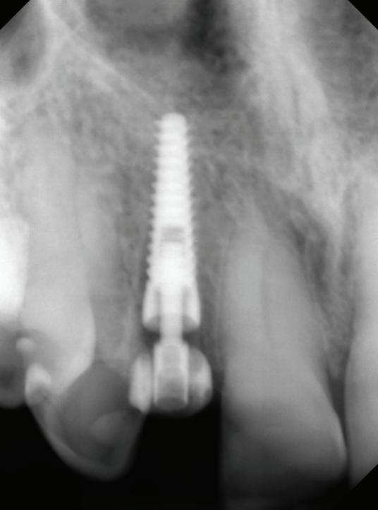
A post placement radiograph is taken to evaluate final implant position and bone graft material fill (Figure 26).
The patient is demonstrated how to seat and remove the appliance and prescribed amoxicillin and Ibuprofen and scheduled for a two week post operative evaluation.
1. Kan JY, Roe P, Rungcharassaeng K, Patel RD, Waki T, Lozada JL, Zimmerman G. Classification of sagittal root position in relation to the anterior maxillary osseous housing for immediate implant placement: a cone beam computed tomography study. Int J Oral Maxillofac Implants. 2011 Jul-Aug;26(4):873-6. PMID: 21841998.
2. Buser D, Martin W, Belser UC. Optimizing esthetics for implant restorations in the anterior maxilla: anatomic and surgical considerations. Int J Oral Maxillofac Implants. 2004;19 Suppl:43-61. PMID: 15635945.
3. Sculean A, Gruber R, Bosshardt DD. Soft tissue wound healing around teeth and dental implants. J Clin Periodontol. 2014 Apr;41 Suppl 15:S6-22. doi: 10.1111/jcpe.12206. PMID: 24641001.
4. Tarnow DP, Chu SJ, Salama MA, Stappert CF, Salama H, Garber DA, Sarnachiaro GO, Sarnachiaro E, Gotta SL, Saito H. Flapless postextraction socket implant placement in the esthetic zone: part 1. The effect of bone grafting and/or provisional restoration on facial-palatal ridge dimensional change-a retrospective cohort study. Int J Periodontics Restorative Dent. 2014 May-Jun;34(3):323-31. doi: 10.11607/prd.1821. PMID: 24804283.
5. Trimpou G, Weigl P, Krebs M, Parvini P, Nentwig GH. Rationale for esthetic tissue preservation of a fresh extraction socket by an implant treatment concept simulating a tooth replantation. Dent Traumatol. 2010 Feb;26(1):105-11. doi: 10.1111/j.1600-9657.2009.00831.x. Epub 2009 Oct 14. PMID: 19843133.
6. Chu SJ, Salama MA, Salama H, Garber DA, Saito H, Sarnachiaro GO, Tarnow DP. The dual-zone therapeutic concept of managing immediate implant placement and provisional restoration in anterior extraction sockets. Compend Contin Educ Dent. 2012 Jul-Aug;33(7):524-32, 534. PMID: 22908601.
Paragon Implant™ Company
8840 W. Russell Rd., Ste. 205
Las Vegas, NV 89148
855.NIZ.GEN5 (855.649.4365) https://paragon-implant.com/