ICYMI: IMTS RECAP INTERFACE SOFTWARE ICS SYSTEMS OCTOBER 2026
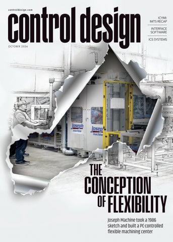
Joseph Machine took a 1986 sketch and built a PC-controlled flexible machining center 2610CD_01_Cover.indd 1
9/28/26 11:42 AM
| MX01USA |
Smart. Modular. Cabinet-free. The MX-System advantage.
Have you taken a serious look at your electrical cabinets lately? Sure, they protect your equipment and have been there right alongside your machines since, well, forever. Maybe you take them for granted, like they just have to be there. They don’t. Our new MX-System has changed automation and controls system design forever. This flexible, space-saving, and intelligent automation hardware platform can completely replace conventional control cabinets and literally transform your machines. Seriously. With pluggable modules for all main areas of automation and control such as the controller, I/O, drives, relays and system modules, the MX-System opens up exciting new possibilities for machine builders, system integrators, and end users alike. Sorry, electrical cabinets, but we think it’s time to retire.
Scan to go cabinet-free and send your enclosures on a permanent vacation!
2608CD_BeckhoffAutomation.indd 1 2610CD_02-07_TOC.indd 2
7/7/26 11:41 1:44 PM 9/28/26 AM
2610C
Looking for the level? Measuring the impossible with radar.
No matter whether your products are liquid or solid, hot, cold, or corrosive — for decades, our radar technology has been setting the standards in level measurement and process automation. We deliver precise, reliable measured values exactly where they’re needed, resulting in more stable processes, greater safety, and maximum product quality. With our radar solutions, innovation knows no limits. Everything is possible. With VEGA.
vega.com
1:44 PM
2610CD_VEGA.indd 1 2610CD_02-07_TOC.indd 3
9/17/26 7:09 2:24 AM PM 9/30/26
ACOPOStrak Fast. Flexible. Productive. ACOPOStrak is a revolution in adaptive manufacturing. This highly flexible transport system extends the economy of mass production down to batches of one. Parts and products are transported quickly and flexibly from processing station to processing station on independently controlled shuttles. • Increase overall equipment effectiveness (OEE) • Boost the return on investment in your machines (ROI) • Shorten your time to market (TTM)
Meet us at Pack Expo Booth S-2451
br-automation.com
B&R | A member of the ABB Group
2610CD_BRIndustrialAutomation.indd 1 2610CD_02-07_TOC.indd 4
9/23/26 11:41 7:27 AM 9/28/26 AM
table of contents
Volume 30, No. 5
22 cover story
The conception of flexibility Joseph Machine took a 1986 sketch and built a PC-controlled flexible machining center Anthony Pigliacampo, Joseph Machine COMPOSITE IMAGE BY BILL ANTKOWIAK, MACHINE IMAGE COURTESY ©BECKOFF
14
29
30
32
machine input
machine safety
data acquisition
product roundup
Unlock transport systems’ value
Integrated control and safety’s impact
Components put machines in motion
How software-driven motion transforms machine design, control and maintenance
Why ICS has evolved from hardwired relays to safety networks
We don’t need another subscription
Mike Bacidore, head of content
Tobey Strauch, contributing editor
Maintenance teams need a voice in automation
Motors, drives and starters get production humming
John Piller, JPiller Design and Consulting
CONTROL DESIGN (USPS 17792, ISSN 1094-3366) is published 6x annually by Endeavor Business Media, LLC. 201 N. Main Street, Fifth Floor, Fort Atkinson, WI 53538. Periodicals postage paid at Fort Atkinson, WI, and additional mailing offices. POSTMASTER: Send address changes to CONTROL DESIGN, PO Box 3257, Northbrook, IL 60065-3257. SUBSCRIPTIONS: Publisher reserves the right to reject non-qualified subscriptions. Subscription prices: U.S. ($120 per year); Canada/Mexico ($250 per year); All other countries ($250 per year). All subscriptions are payable in U.S. funds. Printed in the USA. Copyright 2026 Endeavor Business Media, LLC. All rights reserved. No part of this publication can be reproduced or transmitted in any form or by any means, electronic or mechanical, including photocopies, recordings, or any information storage or retrieval system without permission from the publisher. Endeavor Business Media, LLC does not assume and hereby disclaims any liability to any person or company for any loss or damage caused by errors or omissions in the material herein, regardless of whether such errors result from negligence, accident, or any other cause whatsoever. The views and opinions in the articles herein are not to be taken as official expressions of the publishers, unless so stated. The publishers do not warrant either expressly or by implication, the factual accuracy of the articles herein, nor do they so warrant any views or opinions by the authors of said articles.
ControlDesign.com / October 2026 / 5
7:27 AM
2610CD_02-07_TOC.indd 5
9/28/26 11:41 AM
ONE CABLE TECHNOLOGY
POWER + FEEDBACK | SIMPLIFIED SOLUTION • • • • •
Tested complete system: Components are optimally matched to one another Simplified project planning and design Reduced procurement costs Minimized interface risks between different suppliers Consistent technical support for the entire drive system (952) 224-1400 | sales@kebamerica.com | kebamerica.com
2610CD_KEBAmerica.indd 2610CD_02-07_TOC.indd 61
9/23/26 11:41 9:41 AM 9/28/26 AM
Volume 30, No. 5
table of contents
editorial team editor in chief
Mike Bacidore mbacidore@endeavorb2b.com digital editor
Madison Ratcliff mratcliff@endeavorb2b.com contributing editor
Rick Rice rcrice.us@gmail.com contributing editor
Joey Stubbs joey.stubbs@gmail contributing editor
Tobey Strauch tobeylstrauch@gmail.com columnist
Jeremy Pollard
COLUMNS 9 editor’s page
13 component considerations
A look inside the tech and trends at IMTS
Troubleshooting 4-20 mA
jpollard@tsuonline.com
design/production
Tobey Strauch, contributing editor
Mike Bacidore, editor in chief
10 embedded intelligence
34 live wire
Rita Fitzgerald
Leave nothing unsensed
Battery or supercapacitor? How to choose
rfitzgerald@endeavorb2b.com
Jeremy Pollard, CET
Joey Stubbs, contributing editor
production manager
ad services manager
Jennifer George jgeorge@endeavorb2b.com art director
Bill Antkowiak
11 technology trends
subscriptions
Behind every great HMI is great software
email: customerservice@controldesign.com
Rick Rice, contributing editor
audience development manager
Shirley Patino spatino@endeavorb2b.com
sales team Account Manager
30
Greg Zamin gzamin@endeavorb2b.com 704/256-5433 Fax: 704/256-5434
Account Manager
Jeff Mylin jmylin@endeavorb2b.com 847/516-5879 Fax: 630/625-1124
ALLAHFOTO | SHUTTERSTOCK.COM
Endeavor Business Media, LLC 30 Burton Hills Blvd, Ste. 185, Nashville, TN 37215 800-547-7377
N
ad index
CEO Chris Ferrell COO Patrick Rains CDO Jacquie Niemiec CALO Tracy Kane CMO
B&R Industrial Automation..............................................4
Hammond Manufacturing..............................................28
Banner Engineering ...........................................................8
Hammond Power Solutions..........................................27
Beckhoff Automation.........................................................2
KEB America...........................................................................6
Endress + Hauser..............................................................36
Migatron ..............................................................................17
Fuji Electric..........................................................................28
VEGA Americas.....................................................................3
Amanda Landsaw EVP Manufacturing & Engineering Group Lisa Paonessa VP Content Strategy Manufacturing & Engineering Group Travis Hessman
ControlDesign.com / October 2026 / 7
9:41 AM
2610CD_02-07_TOC.indd 7
9/28/26 11:41 AM
PLUG IN. POWER UP. PROTECT.
S4B Safety Light Curtain
STB Safety Touch Button Compact E-Stop
STB Safety Touch Button
Machine safety doesn’t have to mean more complexity. Bring safeguarding closer to the machine with Banner safety solutions designed for straightforward installation and dependable protection.
Simplify Your Machine Safety.
2610CD_BannerEngineeringCorp.indd 2610CD_08-09_Editor's Page.indd 8 1
bannerengineering.com
9/17/26 11:41 6:05 AM 9/28/26 AM
editor’s page
Mike Bacidore editor in chief mbacidore@endeavorb2b.com
A look inside the tech and trends at IMTS EVERY TWO YEARS, Chicago’s McCormick Place becomes home
the overarching themes of IMTS 2026 were low-barrier
to the western hemisphere’s largest manufacturing technology
automation and background AI.
trade show, the International Manufacturing Technology Show
Recognizing that fewer than 40% of small-to-medium
(IMTS), hosted by the Association for Manufacturing Technol-
job shops currently utilize robotics, exhibitors focused
ogy (AMT). IMTS brings together machine builders, software
heavily on reducing adoption barriers. Automation suppli-
developers, robotics integrators and industrial leaders to show-
ers showcased no-CapEx and low-risk financing models,
case solutions driving productivity and sustainability.
treating robotic cells as operational expenses rather than
Coming off an historic surge in domestic manufacturing
massive upfront capital outlays.
orders, with U.S. metalworking machinery orders exceeding
Other providers debuted teach-by-demonstration robot-
$4 billion in the first seven months of 2026,this year’s event
ics. Rather than requiring complex code, operators manually
showcased an industry expanding capacity, embracing digi-
guide a robot arm through a motion cycle, allowing AI vision
tal transformation and deploying artificial intelligence (AI).
algorithms to automatically adapt to physical part variations.
Registration figures exceeded 90,000 visitors by the show’s
In-machine automation innovations highlighted
conclusion. Almost 1,800 com-
spindle-mounted grippers
panies exhibited, including 400 first-timers. More than 1 million sq ft of exhibit space covered 10 distinct technology sectors. The show welcomed participants from
and part-flipping modules. By
Automation suppliers showcased no-CapEx and low-risk financing models.
113 countries, including representa-
converting standard CNC machines into self-loading cells without external robotic arms, job shops demonstrated ROI in as little as seven weeks.
tion from all 50 U.S. states. And the
Unlike previous years
Smartforce Student Summit saw around 15,000 registrants.
where AI was treated as a futuristic buzzword, IMTS
IMTS 2026 introduced strategic updates to its floor
2026 highlighted pragmatic AI tools embedded directly
layout to reflect the convergence of complementary
into CAD/CAM and quoting pipelines. Software plat-
industrial technologies:
forms demonstrated AI engines capable of analyzing
• Subtractive and Additive Fusion (South Building): For the
CAD files in seconds to verify shop capability, estimate
first time, traditional metal removal and the additive manu-
tooling costs, calculate margins and automatically
facturing sector were integrated side-by-side in the South
program toolpaths. Other systems demonstrated how
Building. This layout allowed engineers to explore hybrid
machinists can adjust feeds, speeds and operation
manufacturing workflows, such as near-net additive deposi-
sequences using natural voice or text commands with
tion paired with five-axis CNC finishing, within a single hall.
built-in safety prompts.
• Expanded Software & Laser Technology (East & West
To address ongoing skilled labor challenges, IMTS ex-
Buildings): The West Building placed expanded focus on Tool-
panded its educational and community programming. The
ing & Workholding, while the East Building housed Software,
Smartforce Student Summit relocated to Level 1 of the North
Quality Assurance and Fabricating/Laser technology sectors.
Building, bringing 15,000 students and educators face-to-
While multi-tasking CNC centers, high-speed water-
face with advanced robotics, digital twin simulations and
jets and heavy press brakes drew continuous crowds,
hands-on machining exhibits.
m ControlDesign.com / October 2026 / 9
6:05 AM
2610CD_08-09_Editor's Page.indd 9
9/28/26 11:54 AM
embedded intelligence
Jeremy Pollard jpollard@tsuonline.com
Leave nothing unsensed AS HUMAN BEINGS, we have always been defined by our
plete, and only then is a problem discovered in the process,
ability to sense—hear, speak, feel, see, taste and smell, to
which is altered after the fact.
name a few. In industry, we need to have the ability to use
To be able to have real-time data to affect the process
use all of these senses, as well as gather other dimensional
and/or machine control on the floor or at the edge is
characteristics such as position, temperature and speed,
invaluable. Using this data for online dynamic changes
for example. Voice-activated control has been floated on the
to the process can only provide for better control, higher
plant floor but has drawbacks that may be obvious.
productivity and less unplanned downtime.
Sensor technology has progressed in the 2000s with vora-
Sensors provide a microscope into the operation of the
cious speed and capability. Yet the pushbutton remains as
process or machine. It gives us feedback on mechanical
one of the mainstays since it allows interfacing of opera-
movement and allows the operators to better understand
tions to the control. Automatic control requires the ability
how the process is running, assuming there is an operator.
to cover all bases to sense all things process or machine
Some automated systems are being monitored and adjusted
control. That includes manual interfacing, as well as pro-
by an operator sitting in a control room looking at supervi-
cess/machine sensing. The main advancements that we
sory control and data acquisition (SCADA) screens.
have seen in the overall system can be classified as edge
Take a nuclear reactor system, for example. There
computing, Industrial Internet
is no one in the system; all
of Things (IIoT), wireless sensing
monitoring is remote.
and energy harvesting. Small single-board computers operating at the edge can support various sensing technologies,
Operators know that a machine is running at peak performance by the sounds it makes.
Machine control, however, would probably have an operator present monitoring the physicality of the output of the machine.
which need to be able to prove
Vision systems could be
and execute algorithms to push
employed to do that monitor-
data to the cloud. Those systems typically would not have a large I/O count but may need specialized I/O to measure and detect variables in the monitored process. It’s just not about limit switches and pushbuttons anymore. Some instrumentation in the field used to be only found
ing. However, should the resulting output not be to spec, the machine could be experiencing a symptom that is not being monitored, such as sound. So many operators know that a machine is running at peak performance by the sounds it makes at the various stages of the process.
in a lab somewhere, such as chemical analysis equipment.
I have seen an operator determine that the hydraulic
Near-infrared (NIR) spectroscopy can be mounted in situ to
pressure was marginally low due to the sound that the die
constantly monitor physical properties in process liquids. I
closing made. It just doesn’t sound the same.
am of the opinion that whatever we need to accomplish in
Can or should sensors replace all aspects of machine
the field can be done using current sensor technology.
and process control? It depends. In an oil refinery, the level
One of the key advancements is the ability to have
of sensory feedback is at the highest level, and yet we still
these digital sensors as part of the intrinsic solution for automatic system control. They can be networked using standard industrial pro-
have accidents and fires. There’s no excuse for not sensing anything these days. With the technology where it is, we can do it all.
tocols, or they can be directly connected using standard instrumentation connectivity. One of the huge benefits is having this data available. In so many cases, testing is done after the process is com-
JEREMY POLLARD, CET, has been writing about technology and software issues for many years. Pollard has been involved in control system programming and training for more than 25 years.
10 / October 2026 / ControlDesign.com
2610CD_10_Embedded Intel.indd 10
9/28/26 11:51 AM
technology trends
Rick Rice contributing editor rcrice.us@gmail.com
Behind every great HMI is great software THE HUMAN-MACHINE INTERFACE (HMI) has been around
ited only by the practicality of a person being able to see the
for a long time. My first encounter with an HMI was a
object on the screen.
cathode ray tube (CRT) in a beast of an enclosure. The
Objects are no longer locked into the invisible grid on the
choice of color was monochrome. It was the latest in
screen and can be placed anywhere in the viewing area.
technology at the time. As I recall, monochrome was the
Ironically, I still use some object placement tools to put most
only choice; there were different colors of monochrome,
objects back into a grid pattern because it is pleasing to my
but just one color could be selected to use for all of the
eye. In fact, I get annoyed when an OEM or one of my own
screen objects.
designers gives me a screen where similar objects are not
HMIs of that vintage were grid-locked, meaning that one could place an object on the screen, but only in a dedicated location on a locked in grid. The objects were pre-defined and could not be modified in any format.
aligned. One might call me old and barbaric, but I care about the aesthetics of the screen. The evolution of the HMI has left us with a hardware device that is basically an industrial computer with a monitor
Navigation was usually via buttons on a touchpad that was located on the bezel around the outer edges of the CRT.
either attached to or near it. What differentiates the various hardware/brand choices is the development software.
The CRT was a display-only, and
My view of HMI development
the operator could only make ac-
software can be divided into two
tions happen by using the touch pad to the side to move the screen highlight around the grid to highlight the objects. Once the correct
The legacy machine-control HMI products led to an evolution of software.
grid was highlighted, the enter
evolved from legacy HMI hardware where the software was designed to direct the development to fit within the confines
button would confirm the action. Numeric entries worked in much the same way. Once
distinct groups. One group has
of the dedicated processor HMI. Screens mimicked a control panel with push buttons, selec-
the entry pointer was on the correct variable, the operator
tor switches, pilot lights. Basically, the HMI was an electron-
would manually enter a new value via the numeric keypad,
ic version of a control board in a factory. The second group
also on the bezel outside the confines of the CRT itself.
of HMI development software is born from the dedicated
Function keys along the side and bottom of the display
SCADA packages. Perhaps I over-simplify things, but I think
could be programmed to perform specific functions. Usually
of the former as machine control and the latter as process
the ones on the bottom were used for screen navigation.
control. The situation is no longer that distinct, but we can
Anyone reading this description of an HMI from back then must think this is barbaric and antiquated, and, well, it
talk about that later. As mentioned previously, the legacy machine-control HMI
was, but we didn’t think so at the time. Like anything in this
products led to an evolution of software as the hardware
life, we take what we are given and make it work to the best
evolved. These products used the screen to mimic the real-
of our abilities. I look back fondly on those experiences and
world controls that an operator would use when interacting
take great pride in what I was able to do with that “barbaric”
with the equipment.
system. Much could be done with the four basics—input (button), indicator (light), numeric and alpha entry.
While improving the quality/clarity of the screen objects, they literally look like their real-world counterparts. A push
Thankfully, HMI has come so much further. Primary to
button, with a label behind it, looks just like the actual
that is the physical format changing from CRT to light-emit-
button on a panel—a selector switch that, when pressed,
ting diode (LED) with variations matching modern television
toggles back and forth through the physical positions that
and computer monitors. Colors are practically unlimited
the real version would have. Pilot lights turn off and on to
and screen resolutions are such that screen objects are lim-
mimic the status of, for example, a motor starter or a critical
ControlDesign.com / October 2026 / 11
2610CD_11-12_Tech Trends.indd 11
9/28/26 11:41 AM
technology trends
photo eye. Navigation buttons, formerly located on the bezel
traffic-light system. We added to it to make it have advanced
around the screen, become buttons on the screen with the
green and stop-and-go flashing signals like a real-life appli-
advent of touch screen technology.
cation. I bring this up because HMI development for me has
Later versions of the development software don’t abandon
always been about taking the building blocks and adding
real life mimicking screen objects but add to the features by
new features to them. The library after nearly 40 years in
allowing the designer to change the color of the nameplate,
the industry is quite extensive, but I am finding that some of
for example, to further highlight the status of the object.
those custom blocks of code and HMI objects are now com-
Objects can flash to show action. Pressing a button will
mon objects offered with the software package. One might
change the object on the screen to show a depressed image,
lament the work that went into those custom blocks, but I
and releasing it returns it to the
find that these are the building
normal raised image. Switching off to the processcontrol HMI products, the approach has always been to visualize the process in a graphical way.
blocks for future development.
The approach has always been to visualize the process in a graphical way.
I’ve always thought of this as the
The software makes it possible. My favorite automation vendor came out with an HMI product a couple of years ago that is breaking the traditional
bigger picture. Machine control is
barrier between machine and
more of unit operation view of the world. Each machine has
process HMI. The approach is from the process-control HMI
its own focus with specific screens to provide a means to in-
side of things but incorporates the usual objects found in a
teract with the equipment. Process control is more about the
machine-control HMI. I had some reservations when this
full scope of the operation with the executive view. There
first came out. I’m in a user group that gets to try out the
is a methodology with these systems in that they are more
software in an online environment where the developers
object-oriented with multiple instances of those objects
watch me use the software without any direction on how to
making up the total system. Screens can be modified on
develop the objects I see on a sample screen. When partici-
the fly and deployed to the client stations with the operator
pating in one of these sessions, I struggled with doing what
rarely aware of a change being made.
I would say were simple tasks until it finally dawned on me
Over time, the differences between a machine-control HMI and a process-control HMI have blurred to the point where there is little difference between the two. Hardware
that this is a process-HMI application that integrates the machine HMI components. I wondered where the developers were coming from when
manufacturers help to integrate the two methodologies
designing this new software/hardware platform, and the
by combining the two approaches via the development
answer was really quite simple. Students working their way
software. Screen objects are multi-layered and have built-in
through college don’t learn PLC and HMI. They learn pro-
functionality that would have taken hours to develop manu-
gramming languages and GUIs. Java, HTML5 and Python are
ally. Most major brands have a library of add-on objects that
the hot topics at school. Everyone has a tablet or a smart-
mesh well with matching data tags in the PLC. Of particular
phone these days, and it occurred to me that the young
interest, the designer can create custom template objects
people graduating from high school and college have a set of
that match user-defined tags in the PLC to expand that.
tools that I would not have even imagined when I graduated
Back when I was coming into the field of automation, the
in the late 1980s.
focus was on the component level design of a control system. This was a great foundation for the rest of my career
RICK RICE is a controls engineer at Crest Foods
but the most interesting class I took was in PLC program-
(www.crestfoods.com), a dry-foods manufacturing
ming. We did a simple project that started with a simple
and packaging company in Ashton, Illinois.
12 / October 2026 / ControlDesign.com
2610CD_11-12_Tech Trends.indd 12
9/28/26 11:41 AM
component considerations
Tobey Strauch contributing editor tobeylstrauch@gmail.com
Troubleshooting 4-20 mA CONTROL SYSTEMS MAY HAVE MANY TYPES OF CIRCUITS.
One way to troubleshoot is to remove the instrument and
The two primary circuits used in process are discrete and
use a multimeter device that can generate a 4-20 mA signal
analog circuits. Discrete circuits are normally on or off
back to the PLC. These instruments are used to check the loop
and have a discrete response matching to buttons and
wiring and the PLC input card and to tune PIDs in the PLC.
switches. Analog circuits may be current based with 4-20 mA or voltage based with 0 to 10 V.
Another way is to use a multimeter in series to measure the current and then have an operator generate a signal by asking
When an analog circuit fails, then electricians typi-
for a low, mid and high range signal that translates to the 4
cally troubleshoot, but electrical engineers will also get
mA, 12 mA and 20 mA readings. Once that is validated without
called to validate the circuit. Plant operators monitor
the device, it can be said that the field device is failed. If the
pressure transducer inputs, levels or motion feedback
field device is reconnected and the physical locations just don’t
circuits such as actuators and valves. These are some
match the 0, 50, 75 and 100% positions, then the device or PID
common transmitter types.
loop needs to be calibrated. There are also mA clamp meters
A 4-20 mA loop failure can be indicated by many things. • Unusual process conditions can cause a report of a fault to the maintenance team. In upset conditions, the instru-
that are valuable for commissioning many circuits. Otherwise, when the transmitter device in the field is removed from the circuit, testing the loop should give indica-
ment can be reading correctly,
tions to the symptoms described
but something process-related is
above. Breaking the circuit into
causing the non-normal indication. If an instrument falls out of calibration, it can also indicate an abnormal reading.
One way to troubleshoot is to remove the instrument and use a multimeter device.
• High loop resistance would
pieces, for example, PLC to the terminal block, terminal block to the field device, allows a segmented approach that can be done systematically so as not to
mean that the transmitter would
waste time. Using proper tools
have trouble maintaining a current signal at a correct level.
like a multimeter and understanding that one must be in
This would cause inaccurate readings, as well.
series to measure current or convert the voltage readings to
• Scaling mismatches between the human-machine inter-
expected mA will help. The other part is understanding what
face (HMI) and programmable logic controller (PLC) can also
the components in the field are actually calling for. Under-
cause inaccurate readings.
standing the type of current loop transmitters that may be in
• PLC card failure could cause an incontinence if the port fails or the card fails. If this is true, then one would expect an abnormal condition on more than one circuit.
a field component can help. Along with this, knowing that the circuit is powered properly will ensure good signal. It never hurts to review basics, and basics for controls
What does a 4-20 mA circuit look like? There are three
engineers is Ohm’s Law. Understanding Ohm’s Law and how
parts to an analog circuit, and there is typically a source (+24
the current transmitter works allows an engineer to build
V), a common (-24 V) and a shield wire. A traditional circuit
a base so that they can look at a circuit objectively and not
has the field device (1), the wiring from the field device to the
from a shotgun troubleshooting approach.
terminal block (2), the terminal block to the PLC input or out-
It is imperative to pick a side of the circuit and work field
put (3). A remote circuit may just be from the field to a remote
to PLC or PLC to field, depending on the symptoms generat-
input/output card rack and then an Ethernet connection to
ing a fault, document findings and then make a decision
the main controller. Also, the HMI will read from the PLC, and
based on facts, not opinion.
some may consider that a fourth part of the circuit since the software may cause an inaccurate reading. An example of an
Tobey Strauch is an independent principal industrial
ISA type sketch is pictured in Figure 1 with locations to test.
controls engineer.
ControlDesign.com / October 2026 / 13
2610CD_13_Component Considerations.indd 13
9/28/26 11:43 AM
machine input
Unlock transport systems’ value How software-driven motion transforms machine design, control and maintenance by Mike Bacidore, head of content
TRANSPORT SYSTEMS HAVE evolved over the years, and these industry veterans should know. Jeff Johnson is mechatronics product manager for Beckhoff USA. John Atchison is sales product manager at Bosch Rexroth. Hans-Peter Kraft is global product manager—ACOPOS 6D and mechatronics services at B&R, a member of the ABB Group. Khyati Desai is FlexLink’s product manager, hygienic solutions. They answered our questions about transport systems, the rise of software, system troubleshooting, data acquisition and human-machine interfaces.
When a machine builder transitions to independent, software-driven transport systems, how does that change the fundamental design relationship between the mechanical engineer and the controls programmer?
Figure 1: Mechanical and controls engineering must co-design the transport concept from the beginning.
completed first and the controls programmer asked to make it run afterward. They must co-design the transport
John Atchison, sales product manager, Bosch Rexroth:
The relationship between mechanical and
concept from the beginning (Figure 1). The mechanical engineer still owns fundamentals, such as
controls becomes a critical aspect of the design.
carrier stability, product support, acceleration limits, transfer
No longer is the transport system a piece you
geometry, accumulation pressure, access and safe mainte-
set and build the machines around. It has become part of
nance zones. The controls engineer defines the carrier state
the process and integrates fully into the machine
model, routing decisions, recipe logic, queue management,
function as well as process.
interlocks and fault-recovery behavior. The most important shared deliverable is an interface contract: station and route
Khyati Desai, product manager, hygienic solutions,
identifiers, sensor and actuator definitions, carrier data, ex-
FlexLink: Although puck and pallet conveyors are
pected cycle times, fault states and recovery rules.
mechanically different from linear-motor independent-mover systems, the same design
This collaboration should start during concept development, supported by simulation or at least a digital
shift appears as soon as routing, carrier identification and
flow model. Early co-design prevents a mechanically
process recipes become software-configurable. Mechanical
elegant layout from becoming difficult to control, and
and controls engineering can no longer work as two
it prevents sophisticated software from depending on
sequential disciplines, with the mechanical layout
unrealistic physical behavior.
14 / October 2026 / ControlDesign.com
2610CD_14-21_Machine Input.indd 14
9/28/26 11:41 AM
machine input
Jeff Johnson, mechatronics product manager, Beckhoff USA:
Software-driven transport changes that dynamic
The relationship becomes much more collabora-
fundamentally. Transport behavior becomes increas-
tive and iterative across the board. The controls
ingly configurable through software rather than being
programmer no longer has to be brought in only
determined solely by mechanical architecture (Figure 2).
after the mechanical design is substantially complete. I’ve
As a result, engineering decisions that were once made
found that the most successful machine designs happen
independently now need to be considered together from
when both engineering disciplines can work together to
the earliest stages of a project.
develop the machine concept from the beginning. A common first instinct is to apply an intelligent trans-
This changes how machines are designed. Instead of focusing primarily on how products can physically move
port system to a traditional linear or rotary indexing layout.
from one process step to the next, engineering teams
The stations remain evenly spaced, every product advances
can focus on how the overall process should perform.
simultaneously, and the longest process still establishes the
Routing, sequencing, buffering and product handling be-
overall machine cycle. That may work, but it leaves many of
come part of a broader system design discussion rather
the technology’s largest benefits unused.
than individual mechanical challenges.
The engineering team should instead begin by examining the duration of every process. How many movers does each station require? Where should products accumulate? Could a longer process be divided or duplicated across two or three stations to shorten the overall cycle? Could the mechanical design of a station be changed to reduce its processing time? Answering these questions requires input from both mechanical and controls engineering. The mechanical engineer still owns critical decisions involving tooling, product fixturing, payloads and overall mechanics. The tooling may also need to accommodate multiple product formats. The controls engineer takes greater responsibility for mover coordination, traffic management, buffering, station synchronization and recipe-driven motion. However, this should not become
Figure 2: Transport behavior becomes increasingly configurable through software rather than being determined solely by mechanical architecture.
a handoff of responsibility from one discipline to the other. It should be a collaboration. Software-controlled mover spacing can also eliminate many mechanical changeover elements and avoid massive amounts of downtime. The best results come when mechanical and controls engineers treat software-defined motion control as a design tool from the outset. Hans-Peter Kraft, global product manager—ACOPOS 6D
and mechatronic services, B&R: The relationship
evolves from sequential hand-offs to true collaborative engineering. Traditionally, mechanical engineers would first solve transport challenges through hardware: conveyors, indexing systems, transfer mechanisms or dedicated kinematics. Controls engineers would then develop automation logic within the constraints defined by the mechanical design.
Figure 3: The competitive advantage shifts toward the ability to combine process expertise, software capabilities and machine design into a scalable and adaptable production concept.
ControlDesign.com / October 2026 / 15
2610CD_14-21_Machine Input.indd 15
9/28/26 11:41 AM
machine input
It also enables a much earlier evaluation of machine
Ultimately, the best systems are those that hide technical
concepts. Increasingly, manufacturers expect layouts,
complexity from users. Technology should help technicians
process flows and throughput scenarios to be validated
understand what is happening, why it is happening and
virtually before physical hardware is available. This al-
what action should be taken next. The easier that informa-
lows teams to identify bottlenecks, collision risks and
tion is to access and interpret, the easier it becomes to keep
performance limitations much earlier in the development
machines running efficiently and reliably.
process, reducing engineering risk and shortening the path to commissioning.
John Atchison, sales product manager, Bosch Rexroth: The
Ultimately, the competitive advantage shifts away
reduction of moving parts creates a shift in the
from mechanical complexity and toward the ability to
maintenance levels required (Figure 6). The data
combine process expertise, software capabilities and
allows for performance tracking in the system
machine design into a scalable and adaptable produc-
itself, to the point where troubleshooting becomes more
tion concept (Figure 3).
focused on a specific area or item. The technician can analyze the data and work only on the area of need instead
As industrial motion relies increasingly on software layers, tracking algorithms and centralized data, what new skills do standard field maintenance technicians need to troubleshoot these systems?
of troubleshooting the entire system. This allows for a quicker response to potential failures.
Hans-Peter Kraft, global product manager—ACOPOS 6D and
mechatronic services, B&R: The interesting paradox is
that as industrial systems become more sophisticated, maintenance should become simpler, not more complicated. Historically, technicians needed deep knowledge of mechanical systems to diagnose issues. They had to understand wear patterns, mechanical interactions and physical failure modes across numerous machine components. Today, many of those complexities are increasingly addressed through software, diagnostics and system transparency (Figure 4). As a result, the most important skill is no longer troubleshooting individual components but understanding system behavior. Technicians need to be able to interpret visual diagnostics, recognize performance trends and understand how different parts of a production system influence one another (Figure 5). That means maintenance is becoming more analytical. Instead of searching for the source of a problem through trial and error, technicians are increasingly supported by digital tools that make machine behavior visible and provide context around potential issues. The ability to interpret that information quickly and make informed decisions becomes critical.
Figure 4: Technical complexities are increasingly addressed through software, diagnostics and system transparency.
16 / October 2026 / ControlDesign.com
2610CD_14-21_Machine Input.indd 16
9/28/26 11:41 AM
machine input
Khyati Desai, product manager, hygienic
solutions, FlexLink: Maintenance techni-
cians need to add software and data literacy to their traditional mechanical and electrical skills. They do not need to become application developers, but they should be able to diagnose the system layer by layer: product and carrier, mechanical transport, sensing, distributed I/O, network communication, PLC logic, routing data and supervisory software. Practical skills include reading PLC diagnostics, understanding basic ladder or structuredtext logic, checking fieldbus topology, verifying RFID or identification data, interpreting drive and I/O status, using HMI event logs and restoring approved software or parameter backups. Technicians also need to understand version control at an operational level—knowing which PLC program, device firmware and
Figure 5: Technicians need to be able to interpret visual diagnostics, recognize performance trends and understand how different parts of a production system influence one another.
recipe set are approved for the machine. A useful troubleshooting method is to follow the carrier’s digital and physical journey. Is the puck or pallet mechanically present? Was it detected? Was its identity read correctly? Did the controller assign a valid route? Did the downstream station acknowledge capacity? This approach is more effective than replacing components based only on the location of the stoppage. Role-based access and cybersecurity hygiene are also essential, because maintenance laptops and service accounts now interact directly with production networks. Jeff Johnson, mechatronics product manager, Beckhoff USA: The technician’s foundational skills remain
extremely important. Maintenance personnel still need to understand the machine’s operating sequences, read electrical drawings, inspect mechanical components, evaluate sensors and actuators and use tools such as a multimeter. What is changing is how quickly they can combine those skills with software- and EtherCAT-based diagnostic information. Once a machine has completed factory acceptance testing (FAT) and operated successfully in production, an unexpected problem is often caused by a physical condition: loss of power, a damaged sensor, a loose connection, mechanical interference, product debris or a failed component. The software did not suddenly rewrite itself. The first task is to determine what changed on the machine.
ControlDesign.com / October 2026 / 17 2506CD_Migatron.indd 1
2610CD_14-21_Machine Input.indd 17
4/28/25 1:50 PM
9/28/26 11:41 AM
machine input
Figure 6: The reduction of moving parts creates a shift in the maintenance levels required.
Human-machine interfaces (HMIs), event logging and data
The next step is to decide what data truly needs to
acquisition tools can make that investigation far more efficient.
leave the controller. Sending every variable, bit and byte
Instead of opening PLC code and tracing through multiple
continuously is rarely useful. Some values only need to
layers of logic, a technician should be able to begin at the HMI.
be transmitted at startup, after a recipe change or when
A well-designed diagnostic interface can show the affected
they cross a threshold. Others can be aggregated into
mover, its physical location, the current machine state, associ-
cycle times, averages, counts or condition indicators in
ated I/O and the sequence of events leading to the stop.
an edge computer. Critical production data, faults and
High-speed intelligent transport and motion systems generate massive amounts of realtime operational data. How should a system integrator architect the edge-computing or PLC infrastructure so this traffic doesn’t bottleneck the primary machine-control loops?
other urgent events should receive priority rather than competing with a constant stream of low-value data. There are cases in which full-resolution data is valuable, particularly for intermittent troubleshooting. A practical approach is to record this data locally in a time-synchronized ring buffer. The system continuously retains a defined period—perhaps the preceding hour—and saves that buffer when a fault or trigger condition occurs. This provides detailed
Jeff Johnson, mechatronics product manager, Beckhoff
before-and-after information without continuously
USA: The guiding principle is simple: Data
flooding a database or cloud service.
collection must never compromise deterministic machine control. The motion and safety
Once engineers identify the variables and calculations that deliver useful insights, they can reduce the ongoing
tasks should retain the required CPU time, network
data stream to the essential values (Figure 7). A message
bandwidth and task priority under the worst anticipated
broker also helps decouple the machine from downstream
operating conditions.
applications. The controller can publish approved data to
That begins with separating control from analytics logically and, where required, physically. Time-critical motion, PLC and
the broker, while authorized systems subscribe to it without querying the real-time controller directly.
machine safety functions should run in deterministic real-
For difficult intermittent problems, synchronized ma-
time tasks with defined priorities and adequate processing
chine vision can add important context. Aligning images
bandwidth. Analytics, database communication, dashboards
with real-world I/O, PLC states and motion data can reveal
and cloud connectivity should operate on separate CPU cores
not just that a fault occurred, but what was physically hap-
or in lower-priority tasks when priorities need to be set.
pening at that moment.
18 / October 2026 / ControlDesign.com
2610CD_14-21_Machine Input.indd 18
9/28/26 11:41 AM
machine input
Hans-Peter Kraft, global product manager—ACOPOS 6D and
This separation becomes increasingly important as
mechatronic services, B&R: The first question should
production systems grow more connected. Operational data
not be how to process the data. The first question
can provide tremendous benefits, from remote diagnostics
should be whether the data creates value.
and process optimization to predictive maintenance and
Many manufacturers collect information because the
continuous improvement initiatives. However, these benefits
technology allows it, not because they have a clear use case.
should never come at the expense of machine performance.
Successful data strategies start by understanding which
The most effective architectures therefore distinguish
information can improve machine availability, quality,
clearly between execution and analysis. Control systems
throughput or maintenance.
focus on running the machine, while data systems focus on
From a technical perspective, real-time control and data
generating insight. When designed this way, manufacturers
analytics should serve different purposes and therefore
gain the ability to continuously improve operations without
operate independently. Machine control requires determin-
compromising reliability or performance.
istic behavior and predictable response times. Analytics, reporting and optimization can operate on separate layers
John Atchison, sales product manager, Bosch Rexroth:
without influencing critical control functions.
Intelligent transport systems include a level of traffic monitoring to ensure operations are performed in a timely manner. Allowing synchronous motion and independent movement of the carriers gives the integrator more control in alleviating bottlenecks both in the software and simplified designs. No longer are queues required for tasks that take longer, as the part can arrive based on need, not buffering. Khyati Desai, product manager, hygienic solutions, FlexLink:
The key principle is to separate deterministic machine control from data-intensive monitoring and analytics. Safety functions, actuator commands, carrier routing decisions and critical interlocks should remain in local controllers or in the cell PLC, where execution is predictable. High-volume historical data, dashboards, condition monitoring and enterprise integration should run in a separate task, processor or edge-computing layer. A practical architecture has three levels. Device or module controls handle immediate functions. The cell PLC manages routing, sequencing and machine states. An edge IPC or industrial server collects time-stamped events, aggregates data and passes selected information to SCADA, MES or cloud systems asynchronously. Raw tags should not be polled at unnecessary rates; data should be filtered at the source and published as events, state changes or calculated KPIs. System integrators should also use network segmentation, managed switches, appropriate quality-of-service Figure 7: Once engineers identify the variables and calculations that deliver useful insights, they can reduce the ongoing data stream to the essential values. © BECKHOFF, 2026
rules and store-and-forward buffering. Database queries, API calls and report generation should never sit inside the time-critical PLC scan. Infrastructure should be sized for
ControlDesign.com / October 2026 / 19
2610CD_14-21_Machine Input.indd 19
9/28/26 11:41 AM
machine input
Alarm design is particularly important. Instead of reporting only that a stop or sensor is active, the HMI should explain the affected location, probable cause, upstream and downstream impact and the safe recovery sequence. Time-line replay and short event histories can help teams understand the chain of events before a stoppage. The HMI should reduce complexity by showing actionable context, not expose every internal tag to every user. John Atchison, sales product manager, Bosch Rexroth: The HMI should become an
Figure 8: For small, fragile or difficult-to-convey products, the X45 puck handling system uses compact round pucks to create a stable and repeatable product interface.
information central point. The entire process can be shown in real time and visually represents how the components are transported through the system. With added data, the ability to adapt instantaneously allows the operator to improve and adjust
worst-case event bursts, such as restart after a blockage,
process before they ever get behind.
not only for average traffic. The objective is to preserve control-loop determinism even when the information layer
Hans-Peter Kraft, global product manager—ACOPOS 6D
is busy or temporarily unavailable.
and mechatronic services, B&R: As production
systems become more flexible and adaptive, the
With advanced transport systems making manufacturing processes highly dynamic and recipe-driven, how should the HMI evolve to help operators visualize complex routing, bottlenecks and system errors in real time?
role of the HMI changes fundamentally. Traditional HMIs were often designed around relatively static machines with predictable movement patterns and
Khyati Desai, product manager, hygienic solutions, FlexLink:
The HMI should evolve from a collection of device screens and alarm lists into a real-time flow map. Operators need to see where carriers are, what state they are in, which route or recipe they are following and where flow is becoming blocked or starved. A good overview combines the physical layout with live information such as queue length, station status, cycletime deviation and the number of carriers waiting, processing or recirculating (Figure 8). The system should present different levels of detail for different roles. An operator needs clear production status and guided recovery. A maintenance technician needs sensor, actuator, network and carrier-identity diagnostics. A process engineer needs trends, route performance and bottleneck analysis.
Figure 9: The Tesseract from Norwalt is an advanced direct-to-object printing machine based on XPlanar maglev transport technology. © BECKHOFF, 2026
20 / October 2026 / ControlDesign.com
2610CD_14-21_Machine Input.indd 20
9/28/26 11:41 AM
machine input
fixed process sequences. Modern transport systems operate very differently. Product routes, priorities and process flows can change dynamically depending on production requirements, machine state or product mix. In this environment, operators do not need access to every underlying algorithm or routing decision. What they need is situational awareness. They need to understand where products are moving, where bottlenecks are emerging and where intervention may be required. This means visualization becomes increasingly important. The HMI should provide clear graphical representations of machine behavior and present relevant information in a way that is immediately understandable. Operators should be able to identify developing issues at a glance instead of having to interpret complex datasets or diagnostic messages. At the same time, information must be tailored to the user.
Figure 10: JR Automation developed the FlexChassis system as a modular automation platform to boost speed to market for customers in multiple industries. The FlexChassis shown is equipped with the XTS linear transport system. © BECKHOFF, 2023
Operators, maintenance technicians and engineers require different levels of detail. Well-designed interfaces deliver the
becomes the constraint, the HMI should make that visible
right information to the right person at the right time without
before it stops the machine (Figure 9).
overwhelming them with unnecessary complexity. As manufacturing systems become more adaptive, user
Alarms need similar context. A useful message should identify the affected mover or product, its location, the
experience becomes a critical part of overall machine
current recipe, the last successfully completed step and
performance.
the event that initiated the stop. Simply displaying an error code or presenting 20 secondary faults caused by one sen-
Jeff Johnson, mechatronics product manager, Beckhoff USA:
sor failure forces the operator to reconstruct the sequence
The HMI should evolve from a collection of
manually and waste valuable time when a machine stops.
buttons and alarm lists into a live operational model of the machine. With products moving on
Visualization should also be role-based. Operators need clear status information and guided recovery steps. Maintenance
dynamic intelligent transport systems, a static screen cannot
personnel need drill-down access to I/O states, network diag-
adequately explain what the system is doing or why.
nostics, event histories, motion traces and component-level
At the highest level, operators should see the actual
information. Engineers may need deeper access to sequence
transport layout, the location and status of each mover,
states, recipe parameters and synchronized historical data.
active product recipes, station conditions and the di-
The HMI must also adapt as the machine changes. When
rection of product flow. Use of color and animation can
a recipe modifies mover pitch, activates parallel stations
highlight blocked movers, accumulating queues or stations
or selects a different route, the visualization should update
operating outside their target cycle times. Rather than
automatically instead of relying on a separately maintained
displaying every available data point, the overview should
static drawing (Figure 10).
direct attention to exceptions.
Ultimately, the HMI should answer four questions im-
The next level should provide production context. Op-
mediately: What is the problem? Where is it? What caused
erators need to see buffer utilization, actual versus target
it? What should the operator do next? When the answers
dwell time, station throughput and the distribution of
are presented clearly, it makes the machine much easier to
products among parallel processes. If a particular station
operate and maintain.
ControlDesign.com / October 2026 / 21
2610CD_14-21_Machine Input.indd 21
9/28/26 11:41 AM
cover story
Joseph Machine took a 1986 sketch and built a PC-controlled flexible machining center By Anthony Pigliacampo, Joseph Machine
22 / October 2026 / ControlDesign.com
2610CD_22-28_Cover Story.indd 22
9/28/26 11:41 AM
cover story
Figure 1 The original drawing of Joseph Machine’s flexible machining center concept, circa 1986. This concept would live on to this day in the form of the company’s powerful jFlex SFMC. © JOSEPH MACHINE, 1986
ngineers often channel their best ideas into a sketch.
While these tasks must be executed at speed, the ma-
When Joseph Machine printed its first brochure in
chines must maintain precision and the ability to rapidly
1986, the company laid out an ambitious machine
change over materials, product types and process flows.
concept in a highly detailed drawing: a flexible
The window and door industry, one of Joseph’s primary
window and door profile machining center capable of
markets, typifies the problem: product designs and end-user
adapting to new products and production needs with-
requirements change much faster than they used to, and
out rebuilding the machine from the ground up. For
manufacturers need machinery that can evolve along with
decades that vision lived in concept and on paper
them rather than becoming obsolete the moment the indus-
(Figure 1). After years of advancements in controllers,
try shifts. For decades, machines were configured for the
drives and automation software, it was time to fully realize
product the end users knew they’d make for the next sev-
this concept to the quality standards of Joseph Machine.
eral years. That’s no longer the case. End users need truly
Our vision of the flexible machining center now has more clarity than ever. But to make the concept real, we had to embark on a rapid migration from a traditional control sys-
flexible machines that can be retooled and reprogrammed quickly as new products are developed. The problem was that the automation system was often
tem, that had reached its limits, to advanced PC-based con-
the limiting factor. Traditional motion control systems
trol and EtherCAT-enabled servo technology from Beckhoff.
forced designers into complex fixed mechanical solutions
The goal was to enable high throughput, multi-axis machin-
and made coordinated multi-axis motion difficult, slow or
ing centers with coordinated motion control that are highly
unreliable, even when
modular, serviceable and adaptable in ways that were previ-
high axis counts were
ously out of reach. It took 40 years for the automation and
promised by vendors.
controls technologies to catch up to this flexible machining
Processor bottlenecks
center concept with 30 axes of motion or more.
from outdated controllers and slow fieldbuses
Sketching out the solution for a rapidly changing industry
produced unpredictable
Joseph Machine’s core business is straightforward in de-
complicated diagnostics.
scription but complex in execution. “Our ‘start to finish’ so-
Ladder logic programming
lutions can cover every aspect—fabrication, cutting, punch-
models were rigid and
behavior at full speed and
ing, welding, glazing, hardware insertion and cleaning—to cost-effectively assemble window and door frames made of PVC, Fiberglas or aluminum in under 60 seconds,” says Tom Vajdic, vice president of sales at Joseph Machine (Figure 2).
2610CD_22-28_Cover Story.indd 23
Anthony Pigliacampo is owner and CEO of Joseph Machine.
9/28/26 11:41 AM
cover story
Figure 2: Paxton Shantz (from left), digital manufacturing industry manager, Beckhoff USA; Tom Vajdic, vice president of sales, Joseph Machine; and Albert Arustamyan, controls engineering manager, Joseph Machine. © BECKHOFF, 2025
cumbersome to change. Field wiring
States that gave us all the
and control cabinet complexity cre-
confidence we needed.”
ated long commissioning cycles and maintenance headaches.
Figure 3: The jFlex SFMC is a truly flexible machining center based on 40 years of Joseph Machine expertise and automation technology from Beckhoff. © BECKHOFF, 2025
To speed up engineering, we took the extra
engineering team set strict param-
USA’s Special Projects Team (SPT).
A control stack layered with flexibility
eters for a new control platform: it
After building an internal testbench
Joseph’s new machines such as the
had to offer high-performance, tightly
in early 2024 and proving concepts,
jFlex and the jFlow PVC welder/cleaner
coordinated motion for potentially
we ramped up to a 32-axis, jFlex
are now based on Beckhoff’s PC-based
hundreds of axes; it had to support a
SFMC fab center with four indepen-
controls and EtherCAT, which cover all
single software engineering environ-
dent CNCs and dual pushers by Q3 of
areas of automation and motion con-
ment up and down the control stack;
2024 (Figure 3).
trol (Figure 4). On simpler machines
With those constraints in mind, our
step of partnering with Beckhoff
it had to simplify commissioning,
“We knew the 32-axis jFlex would
with fewer axes, Joseph uses CX7000
wiring and service; and it had to be
be a big undertaking, so we had one
embedded PCs with ARM Cortex-M7
open to freely integrate third-party
of our senior software engineers
and integrated I/Os. For high-end ap-
sensors and devices. After an exhaus-
work intensively with a Beckhoff
plications, Beckhoff’s fanless C6025
tive evaluation in 2022 that examined
SPT engineer for a couple months
ultra-compact industrial PCs with
many of the major names in industrial
to develop the machine controls,”
processors up to Intel Core i7 (four
controls, we locked in on a solution.
Albert Arustamyan, controls engi-
cores) provide the necessary comput-
“We evaluated many manufac-
neering manager at Joseph Machine,
ing power to run complex, multi-axis
turers, and Beckhoff checked all
adds. “The Beckhoff SPT team truly
motion on machining centers.
the boxes,” Vajdic says. “It’s a fully
understood what we were doing, and
integrated system in all aspects of
the collaboration compressed the
neck for the controls as EtherCAT
hardware, software and networking
timeline to a much better machine at
delivers deterministic, high-speed
with a level of support in the United
the end of the project.”
communication and synchronization
There is no communication bottle-
24 / October 2026 / ControlDesign.com
2610CD_22-28_Cover Story.indd 24
9/28/26 11:41 AM
cover story
Figure 4: The machine can costeffectively assemble window and door frames made of PVC, Fiberglas or aluminum in under 60 seconds. © BECKHOFF, 2025
Figure 5: EtherCAT delivers deterministic, high-speed communication and synchronization across dozens of motion axes and distributed I/O.)
across dozens of axes and distributed I/O (Figure 5). Beckhoff’s openness to multiple protocols, EtherCAT’s broad industry support and the availability of gateways and bus couplers have been major enablers. “With our
© BECKHOFF, 2025
previous system, integrating IO-Link sensors required unwieldy custom file management and cumbersome firmware updates,” says Arustamyan. “With EtherCAT and TwinCAT, it’s
roughly 50% and eliminated laborious
servo drives and AM8000 series servo
much more straightforward.”
field wiring.” Arustamyan says. “All
motors with One Cable Technology
EtherCAT Boxes feature standard M8
(OCT) paired with Beckhoff gearboxes
benefits in the IP67 rating of the
and M12 connectors that sped up I/O
(Figure 6). The built-in AX-Bridge tech-
machine-mountable EtherCAT Box
system cabling and removed the need
nology to feed power to all connected
modules. EtherCAT P and One Cable
for screwdrivers and wire strippers to
servo drive modules meant we could
Automation reduce wiring complex-
install I/O modules.”
substantially reduce the wiring and
The Joseph team found additional
ity by combining power and com-
As the motion control aspects of the
number of required fuses compared to
munication lines into one, reducing
new machines were mission-critical,
the previous drive system (Figure 7).
the cable count significantly. “Our
we embraced Beckhoff’s drive tech-
Additionally, energy-saving AA30x3
move to EtherCAT P cut our cabling by
nology, such as the AX8000 family of
electric cylinders allowed us to
ControlDesign.com / October 2026 / 25
2610CD_22-28_Cover Story.indd 25
9/28/26 11:41 AM
cover story
Figure 6: AM8000 servo motors with One Cable Technology further streamlined cable runs and installation time for Joseph Machine. © BECKHOFF, 2025
replace power-hungry hydraulic and pneumatic solutions, most notably in punching processes that were historically hydraulic. “Hydraulic cylinders present many safety complications along with maintenance and cleaning requirements,” Arustamyan says. “With servo-based punching via electric cylinders, we gain speed, safety, energy efficiency and flexibility in force profiles and retraction behavior with minimal maintenance and cleaning requirements.” Joseph has also begun implement-
Figure 7: AX8000 servo drives with AX-Bridge technology for fast power connection helped Joseph substantially reduce the wiring and number of required fuses. © BECKHOFF, 2025
ing cabinet-free motion control technology with AMI8100 series compact integrated servo drives.
Motion Designer tools
This series combines a servo motor,
allow the entire Joseph
servo drive and fieldbus connection
software team to specify
in a space-saving motor design in the
and configure different
power range up to 48 Vdc. AMI8100
drives, motors and other
integrated servo drives are suitable for
mechanical components
all motion requirements up to 400 W.
without requiring a core
These drives can be placed directly on
motion specialist to do
the machine outside of control cabi-
all the work.
nets and without upstream I/O. “With
The ability to write
the AMI8100 series, we can implement
modular, reusable code
high-performance motion control and
blocks and apply CNC
save space in more cost-conscious ap-
paths with variables
plications,” Arustamyan adds.
rather than recreating
Beyond the hardware, TwinCAT
code across hundreds
3 automation software delivered
of locations changed
additional engineering efficiencies.
how the company
With many Joseph machines requir-
approaches machine
ing dozens of axes of motion control,
development (Figure 8).
TwinCAT 3 NC PTP is used to cover
“Now we can do coor-
development for up to 250 NC axes
dinated, interpolated motion that’s
per machine. Our software engineers
smooth and precise, and, if we need
gravitated to structured text program-
to change a radius or a start point,
ming and TwinCAT’s motion libraries,
we edit it once in the G code, and it
kinematics and camming. TwinCAT
takes effect on every fabrication the
Figure 8: TwinCAT automation software helped Joseph Machine write modular, reusable code to save development time for multiple machine lines. © BECKHOFF, 2025
26 / October 2026 / ControlDesign.com
2610CD_22-28_Cover Story.indd 26
9/28/26 11:41 AM
cover story
Figure 9: The jFlex SFMC features tool changers, saw cutting, variable angles and easily movable clamps for flexible production.
ting, variable angles
The simplification of commission-
and easily movable
ing and the cabinet-free approach to
clamps (Figure 9).
I/O and motion control have created
“High-speed, coordi-
positive ripple effects across Joseph
nated motion from
Machine’s business. Labor, commis-
Beckhoff is crucial
sioning time and cabinet size have
for successfully in-
all been reduced. “By minimizing ca-
troducing a powerful new machine
bles, terminal blocks and real estate
like the jCNC,” Arustamyan says.
from machine-mountable EtherCAT
© BECKHOFF, 2025
machine performs,” Arustamyan says. “TwinCAT code reusability from machine to machine allows us to focus more on software development, so we can introduce more exciting feature extensions.” The switch to Beckhoff has enabled Joseph to realize tangible performance enhancements. The most visible improvement is in the motion capabilities: Joseph can now execute truly simultaneous, overlapping process steps and tool actions that were previously sequenced serially. The platform supports concepts like “tied tooling,” where multiple tools hit a dimensional location simultaneously, and multi-track operations that process multiple parts at once, enabling impressive throughput gains without sacrificing product quality.
The 40-year vision, realized
Power Solutions, Built to Last. We’re working closely with customers around the world to build a future that’s more reliable. Our engineering, sales, and support teams are here for you. Transforming the world’s energy with innovation and commitment.
With the jFlex SFMC and jFlow, Joseph Machine has translated a long-held ambition from paper to the plant floor. These machines give window and door manufacturers equipment that is reliable, reusable and adaptable for high-throughput production. Joseph is already planning the next steps such as an upcoming jCNC machine center with pusher-based infeed that leverages TwinCAT Kinematics for its five-axis CNC tooling in a single-track or multi-track design. The solution also features tool changers, saw cut-
Learn What A True Partner Can Do For You. hammondpowersolutions.com
2610CD_22-28_Cover Story.indd 27
9/28/26 11:41 AM
World-Class Products Engineered for Your Projects
We believe great engineering is about more than products — it is about helping customers solve challenges, improve efficiency, enhance reliability, and build for the future. That is why we design our technologies to deliver performance, durability, and long-term value across a wide range of demanding applications.
Figure 10: Machine-mounted EtherCAT Box and EtherCAT P Box modules helped reduce required cabinet space and cabling. © BECKHOFF, 2025
(866) 238-5126 • americas.fujielectric.com/world-class Box I/O and drive technology, we have been able to downsize electrical cabinets by an estimated 15 to 7/21/26 1:2220%,” PM Arustamyan says (Figure 10).
2608CD_Fuji.indd 1
Another avenue under consideration at Joseph is Beckhoff’s MX-System for cabinet-free automation. “It’s
INDUSTRIAL ENCLOSURES THE LARGEST SELECTION OF STEEL, STAINLESS STEEL AND NON-METALLIC ENCLOSURES
clear that the fully machine-mounted MX-System can add a lot of value on machines where floor space is at a premium,” Arustamyan adds. This would dramatically extend the gains already made from cabinet-free I/O and motion control. With each new system Joseph Machine ships with PC-based control, the payoff for that 40-year-old flexible machining center sketch becomes clearer: streamlined designs, improved performance, smaller footprint and more reliable machines. We’re very happy that we chose this path. Working with Beckhoff feels like
IN STOCK!
a true partnership and an extension of our team. Our machines are now built with the right building blocks for the future of flexible machining, and
www.hammondmfg.com 28 / October 2026 / ControlDesign.com 2403CT_Hammond.indd 1
2610CD_22-28_Cover Story.indd 28
ultimately that’s a game changer for our customers.
2/13/24 3:03 PM
9/28/26 11:41 AM
machine safety
Integrated control and safety’s impact Why ICS has evolved from hardwired relays to safety networks by Tobey Strauch, contributing editor
AN INTEGRATED CONTROL AND SAFETY (ICS) system is a
data. Digital encoder protocols allowed engineers to
centralized architecture that combines basic process control
pack a bunch of things into one cable.
and safety control measures into one system. Some may
The reason for discussing the shift from three cables to two
argue that safety has always been integrated, since controls
in motion systems is that these technologies also impacted
engineers used to wire safety relays directly into the feed
the integrations of safety into one architecture and its inclu-
that provided a machine with control power. What is the No.
sion in the PLC platform. Protocols allow cyclic redundancy
1 thing needed to turn a machine on? Control power.
check (CRC) protection and time-stamped data, meaning
No safety circuit, no control power, no outputs, because
that, though safety is included in the architecture of a control
the control power relay was in the circuit that sourced the
system, safety functions have their own path and can be
programmable logic controller (PLC) outputs.
deterministic the same way when safety functions were wired
More complex systems like burner
separately, isolated and verified by external
management systems would have a
devices. When engineers found they could
systems engineer build a duplicate rack
separate the data and save a cable for motion
and if anything failed in the one rack,
systems, yet still provide functional safety,
it would fail over to the secondary rack.
they applied the ideas to I/O and PLCs.
Typical machines did not take it that far,
Why? CRC protection, sequence checks,
but sometimes the relays for safety were
timestamp verifications and a safety run
quite complicated just to control power.
time system that is password protected
Systems progressed to smart relays. Now
internally on the PLC. This is why, when a
systems use integrated input output cards
safety component is changed on a safety
and safety PLCs.
network, then the safety PLC has to “re-
Prior to getting integrated safety I/O, motors and encoders used three cables. Drives
REBEKA KHATUN43 | SHUTTERSTOCK.COM
did not have safe torque off (STO) feedback. Drives have progressed to safe torque off functions, and encoders for
sync,” if you will, with all of the components and register the new device. Thus, each
safety component has an individual identification. Components are on the process network, but logic can be
motion systems do not require three cables any longer. Why
isolated, meaning that a runtime process can be constantly
did we used to require three cables?
checking safety while the machine goes through process
There was a cable for motor feedback. There was a cable for encoder feedback. There was a cable for auxiliary or
logic, but do so on an integrated architecture. Integrated safety systems would not be possible except
safety feedbacks to include motor thermal sensors, brake
for the motivation to reduce cables in motion systems.
control, external limit switches or safety interlocks to pre-
Once the encoders could deliver SIL-rated data, then
vent overruns. Signals could not be mixed. Now, the power
fieldbus safety protocols emerged. This is why safety
cable can be used for power, braking and thermal sensing.
components can legally claim SIL or PL ratings. Engineer-
The feedback cable may have position feedback, veloc-
ing a safety architecture on an integrated controls network
ity feedback, temperature monitoring, motor nameplate
means the engineer should understand which components
data, diagnostics, safety position and commissioning
are allowed to create a safe system.
ControlDesign.com / October 2026 / 29
2610CD_29_Feature 2.indd 29
9/28/26 11:44 AM
data aquisition
We don’t need another subscription Maintenance teams need a voice in automation by John Piller, JPiller Design and Consulting
MANUFACTURING CAN BE a simple business and quickly
I tell this story for a reason; I liked the solution and think
become an extremely complex one. For more than a
it is a good choice. But it is not a solution for everyone. I
decade, I’ve attended automation trade shows, usu-
would even say there is a very small market that this is a
ally wearing my newsboy hat. Every year, I leave with
great fit for. It is an OK solution for many.
the same observation: many solutions are presented as
I use it as an example of how a cool solution to the purchas-
though every manufacturer operates the same way.
ing team becomes a potentially large added task to the main-
One facility may have a team of controls engi-
tenance team. And, in my experience, the maintenance team
neers, while another relies on a maintenance man-
is last to be invited to the table of discussions, and, when they
ager who wears every hat from
are there, they are not as equipped
electrical to facilities.
with the current technology avail-
I have worked in facilities and
able until they get it into practice.
have worked for clients that fit
By then, it is already installed and
both modes. A common theme I
needs to work, even if it was not
see is the options are plenty. And
the correct tool. An example would
industry solutions providers are
be using a sledgehammer for a
glad to sell their single-source
16-penny nail. Does it work? Yes. Is
solution. For example, I was
it not only less than ideal, but also
recently at a show this sum-
harder than it needs to be? Yes.
mer and stopped at a booth for
This philosophy has spread by
a robotics company. They would
both established automation com-
provide a one-stop, full system
ponent suppliers and new “smart”
along with service after the sale. I was hooked. Then I asked, “Where does your solution start in the client’s system?”
ALLAHFOTO | SHUTTERSTOCK.COM
solutions with venture-backed money startups that are providing
a single solution for making an Industry 4.0 solution.
I received a puzzled look in the salesman. He said, “It is
I have seen suppliers connect their energy-monitoring
a complete solution.” I then pressed on, using an example
equipment to motors and other large loads to tell you where
of a dog-food packing facility where the complete solution
you are spending money. “Just use our online system to
would move from the raw goods to a kibble, to filling the
monitor your data. Subscribe with a monthly fee.”
bags with kibble, and then stacking the bags on pallets. This process is simplified for brevity, of course. From that description, the one-time “complete solution”
Another trend I have seen is based on failure predictions. Add my module that measures vibration and temperature to your machine, send your data to my online portal, and
went from the exit of the machine filling of the bag to the
one more monthly fee. I know a facility that did this, and the
stacking on the pallet. A maintenance team would need
maintenance director had a monthly meeting with the “cus-
to have a new system to master from the filling machine,
tomer service manager (CSM),” where they kept adding tasks
which included a robot, new processor, different convey-
to his PM list for a mixer that had a harmonic vibration at 200
ors, different motors or different motor controls.
rpm speed. The mixer operated at 800-1,000 rpm. It only had
30 / October 2026 / ControlDesign.com
2610CD_30-31_Feature 3.indd 30
9/28/26 11:41 AM
data aquisition
that “excessive” vibration for 2-5 min-
and business systems share informa-
John Piller is the
utes on startup. It had been torqued as
tion through open standards. They
founder of JPiller
much as it could; the thing just did not
can replace an application without re-
Design and Consulting.
like 200 rpm. But the CSM would not
building the factory. The factory owns
Contact him at
remove it from the PM task list because
the data, not the application.
jpiller@jpillerdc.com.
the “smart” cloud would flag it. I’m not even sure the CSM could remove it. So, every week, a maintenance worker had to touch that mixer and answer why it was in failure mode, even when it was not. And they paid a service fee for that extra time that was spent on that task. The subscription service model of clouds and software-as-a-service (SaaS) products feel like streaming services to me. We cut the cable to get on-demand shows for lower cost, and now we have five subscriptions where we still get to watch TV, but it’s not the solution we thought we were getting, nor did it really save money. Manufacturers, as I see it, need to own their architecture—one built on the standard technology solutions that they are comfortable with maintaining. Know how it works with their process and why it works for them. Then find new adaptations to apply to that process and technology. Sometimes a subscription is the right answer, and sometimes a task of packaging off loaded to a single solution provider is the right answer. But do it with a purpose and coordinated with the team involved with using it, maintaining it and servicing it. Common architecture, owned by the manufacturer, is a key in making sure system integrators or aaS solutions are harmonious with the systems. The most successful manufacturers I have worked with are not the ones with the newest software or the most impressive dashboards. They are the ones that have built a common architecture where machines, sensors
2610CD_30-31_Feature 3.indd 31
9/28/26 11:41 AM
product roundup
Components put machines in motion Motors, drives and starters get production humming Beckhoff AF1000 VFD
form a complete drive, inverter, motor, encoder and cable
Beckhoff’s AF1000 variable
package. The KEB OCT system includes its S6 servo drives
frequency drive (VFD) is fully
(0.75 kW to 7.5 kW, housings 2 and 4) and F6 VFDs (2.2 kW
integrated into the TwinCAT
to 37 kW, housings 2 and 3), both equipped with the PRO
automation system via Ether-
control board and Safety Module 5.
CAT, providing the familiar
KEB America / www.kebamerica.co
commissioning convenience and built-in diagnostics found in Beckhoff’s servo drive technology. The AF1000 VFD is
Yaskawa CNC software
available in two different versions: one for a single-phase
Yaskawa’s Compass 2, the CNC soft-
supply of 240 Vac with a power range of 0.37 kW (0.5 hp) to
ware for iCube Control, is optimized
1.5 kW (2 hp), and one for a three-phase supply up to 480 Vac
for CNC routers, designed to deliver G-
with a power range of 0.37 kW (0.5 hp) to 5.5 kW (7 hp).
Code processing, macro logic and path
Beckhoff / www.beckhoff.com
planning for maximum productivity. With Compass Designer, machine tool builders can use the included example user interface to start cutting quickly or
SEW-Eurodrive PxG planetary servo gear
create their own user interface. Compass Designer is used
SEW-Eurodrive’s PxG plane-
application, without writing any C# code.
tary servo gear unit portfolio
Yaskawa / www.yaskawa.com
to create a fully customized CNC HMI as a Windows WPF
includes the PxG economy series. The P1.G, P2.G and P3.G gear units are designed for Typical uses include packaging equipment, assembly ma-
AutomationDirect Ironhorse ac drives
chinery, material handling systems, carton erectors, gantry
AutomationDirect IronHorse ES1
robots and machine tool portals. Each performance class
ac drives allow simple ac motor
addresses a different level of mechanical demand. P1.G
control for 3/4 up to 2 hp 230
is intended for standard applications with relatively low
Vac three-phase motors from a
applications with low to medium technical requirements.
overhung loads. P2.G provides additional load capacity for
single-phase 120 Vac or 230 Vac
applications with increased radial forces.
input. They are available in an open-chassis or NEMA 4X enclo-
SEW-Eurodrive / www.seweurodrive.com
sure. The NEMA 4X models can be purchased with an optional enclosure-mounted FWD-REV switch. Motor speed is adjustable with an included potentiometer (enclosure mounted on
KEB America S6 servo drives with One Cable Technology
NEMA 4X models) or from an external 0-5 Vdc follower input. AutomationDirect / www.automationdirect.com
KEB America S6 servo drives drives (VFDs) are One Cable Technology (OCT) systems. The
NORD variable frequency drive
OCT pairs KEB S6 and F6 drives with matching servo mo-
The NORDAC Pro SK 500P
tors from the TA and Dynamic Line series, plus OCT motor
variable frequency drive’s
cables available in lengths up to 50 m. These components
compact, book-size design
and F6 variable frequency
32 / October 2026 / ControlDesign.com
2610CD_32-33_Round Up.indd 32
9/28/26 11:41 AM
product roundup
enables side-by-side installation without gaps, which is
ERH’s variable-speed control allows precise adjustments.
designed to make it easy to integrate into the cabinet and
ERH comes pre-configured for immediate use, making setup
reduce volume, installation space and costs. NORDAC Pro
quick and hassle-free. Its compact and lightweight build
VFDs are adaptable to individual application requirements
allows for easier integration. With an IP65-rated enclosure,
across industries such as intralogistics, bulk material
ERH is designed to withstand demanding environments
handling and packaging. They are compatible for operation
while maintaining efficiency and durability.
with three-phase asynchronous motors.
ABB / www.abb.com
NORD Drivesystems / www.nord.com
Phoenix Contact Contactron speed starter
Applied Motion servo drive Applied Motion Prod-
The Phoenix Contact Contac-
ucts’ M5 servo series includes built-in Q programming,
tron speed starter accommo-
full closed-loop control using a secondary encoder, gantry
dates higher horsepower re-
synchronization and Safe Torque Off (STO). The built-in
quirements up to 10 hp (7.5 kW). It provides all the functions
Q programming capability allows motion programs to be
necessary for different speeds, ramp start and safe stopping
created, stored and executed directly from the servo drive.
with the Safe Torque Off (STO) function. Additions include
Machine builders can implement positioning sequences,
five new power classes: 3, 4, 5, 7, and 10 hp. Each has a model
homing routines, conditional logic,.
with and without the EMC filter. Like the original products in
Applied Motion Products / www.applied-motion.com
the line, this version has an intuitive, user-friendly interface. Phoenix Contact / www.phoenixcontact.com
Kollmorgen PCMM2G Essentials controller Siemens drive system
The Kollmorgen Essentials
Siemens Sinamics S220 offers a drive sys-
PCMM2G Essentials controller
tem with comprehensive simulation and
is designed to allow machine
analysis capabilities, along with advanced
builders to right-size perfor-
connectivity features that enable full in-
mance, scalability and budget
tegration into digital work processes. The
to configure a complete, cost-effective motion system. The
multi-axis control unit, CU320-3, is the
8-axes PCMM2G Essentials controller offers the same perfor-
technological heart at the core of Sinamics S220. The CU320-3
mance and integration capabilities of the original PCMM2G at
has the ability to operate up to 12 axes on a single control unit.
a price point scaled for lower-axis-count applications.
The Drive-Cliq-Express interface, with a speed of 1GBit/s, is
Kollmorgen / www.kollmorgen.com
designed to ensure rapid data transfer. A test pulse method using three voltage sensors per axis is designed to enable sensorless control with near-encoder quality.
Bardac smart drive
Siemens / www.siemens.com
The Generis dw4Q smart drive from Bardac provides four-quadrant regenerative ac motor control with near unity power factor using a
ABB ERH motor
high-performance, direct line switching tech-
The ABB ERH motor’s IES5 has seam-
nology. It is designed to offer substantial line
less plug-and-play design and is com-
harmonics and comes complete with drive.
pact and lightweight. With IES5 ef-
web distributed control over Ethernet for system integration.
ficiency, ERH is designed to cut power
Initially available up to 30 hp with UL, CE, STO, FCC.
costs while improving airflow control.
Bardac / wwwbardac.com
ControlDesign.com / October 2026 / 33
2610CD_32-33_Round Up.indd 33
9/28/26 11:41 AM
live wire
Joey Stubbs joey.stubbs@gmail.com
Battery or supercapacitor? How to choose MY FIRST EXPOSURE to an “industrial” uninterruptible
opment of the supercapacitor that a short-duration capacitor-
power supply (UPS) was in 1993, but it wasn’t as elegant of a
based UPS became practical for industrial controllers.
solution as you are probably visualizing.
Supercapacitors approach energy storage differently.
While attending community college, our programmable
Instead of storing energy primarily through a chemical
logic controller (PLC) class took a field trip to a packaging
reaction like a battery, they store electrical energy electro-
plant. When looking in the controller cabinet, I noticed that
statically. This gives them characteristics useful for short-
the PLC’s power leads originated from a DeWalt 24 V cordless
duration power backup.
drill battery pack sitting in its charger. If power was lost, the
One major advantage is cycle life. Batteries gradually
PLC continued to run from the cordless drill battery for long
wear as they undergo repeated charge and discharge cycles.
enough to save its data and shut
Supercapacitors can tolerate
down, as opposed to just power off abruptly and lose critical data. That was not the most elegant solution, to be sure, but for that engineer and application, it filled
dramatically more cycles, mak-
Batteries gradually wear as they undergo repeated charge and discharge cycles.
the bill. Today, we have more sophisticated options, but, as this example from more than 30 years ago showed, when power goes away, a PLC doesn’t necessarily need to keep running for
ing them attractive for machines that experience frequent power disturbances. They can also charge and discharge very quickly, allowing a supercapacitor-based UPS to recover its
stored energy rapidly after a short interruption. However, there is a tradeoff. Supercapacitors generally
hours. Sometimes it just needs enough power to come to a
provide high power density rather than high energy den-
controlled shutdown.
sity. They can deliver substantial power quickly but aren’t
Battery-based UPS systems have been successful because
necessarily the best choice when a load must operate for a
they can store substantial amounts of energy and provide
long time. The question isn’t whether supercapacitors can
backup power for minutes or even hours. However, many fac-
replace batteries everywhere. It’s whether the application
tory power interruptions are much shorter. A machine may
actually requires the characteristics of a battery.
experience voltage dips or brief interruptions that require
Factory lines contain numerous loads where short-dura-
only seconds of backup power. Repeatedly cycling a battery for
tion backup can be valuable. A PLC may only need enough
these events can eventually create a maintenance concern.
energy to recognize a power loss and execute a controlled
This highlights an important distinction between energy
response. An industrial PC may need several seconds to
storage and power delivery. Batteries are excellent at storing
save critical information and shut down properly. Remote
energy for extended periods, but not every automation ap-
I/O and industrial networking equipment can also benefit by
plication requires extended backup.
staying powered through a brief disturbance.
For a graceful controller shutdown, there may only need
This changes how an engineer might approach UPS siz-
to be a couple of seconds of power required. This is where
ing. Instead of asking only, “How many minutes of backup
capacitors come in. In the not-so-distant past, a conventional
do I need?” it may be more useful to ask, “What does my au-
capacitor did not exist that could do the job. I remember the
tomation system need to accomplish when power is lost?”
ongoing joke in some of my engineering classes of sending a new student to get a 1 Farad (1F) capacitor. Inevitably, one of our professors would do a calculation in front of the class for
Joey Stubbs is a former Navy nuclear technician, holds a BSEE
how physically large a 1F capacitor would be—approximately
from the University of South Carolina, was a development
the size of a large refrigerator. It certainly wasn’t something
engineer in the fiber optics industry and is the former head
you would solder onto a circuit board. It wasn’t until the devel-
of the EtherCAT Technology group in North America.
34 / October 2026 / ControlDesign.com
2610CD_34-36_Live Wire.indd 34
9/28/26 11:41 AM
2610CD_34-36_Live Wire.indd 35
9/28/26 11:41 AM
Move quickly, measure simply.
er, l p m si The etter. the b ow! rn Orde
Endress+Hauser’s Micropilot radar sensors FMR10B, FMR20B and FMR30B stand out with fast commissioning and intuitive operation. Setup wizards guide you through each step – your device is ready to use in less than 3 minutes.
Simple and efficient level measurement. Order now! www.us.endress.com
2510CD_EndressHauser.indd 2610CD_34-36_Live Wire.indd 136
9/5/25 11:41 9:48 AM 9/28/26 AM