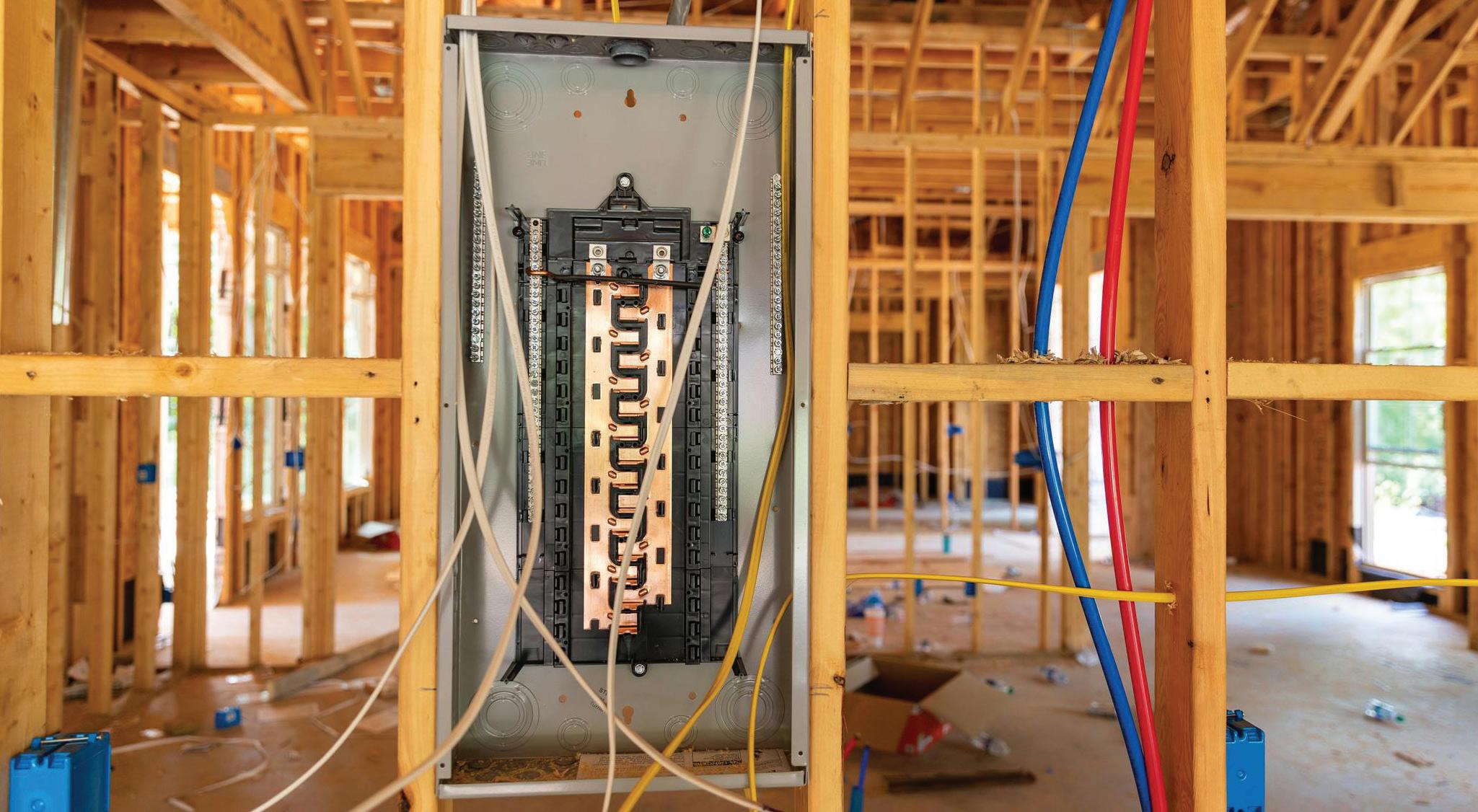
From planned projects to last-minute needs, The Home Depot delivers on your schedule—same day, next day or any day you need to keep the job moving. When and Where You Need It.
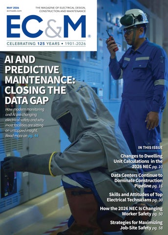
why most facilities are sitting on
Clarified rules and new requirements help electrical contractors, designers, and maintenance teams reduce
conditions.
Complacency and poor communication are the top concerns in workplace safety. Four experts explain why — and offer tips to protect employees, trades, and clients.
Changes to dwelling unit calculations in the 2026 NEC
Data centers continue to dominate construction pipeline
How to determine the most effective fall protection solution on job sites
The path to excellence: skills and attitudes of top electrical technicians
the impact of utility switching transients and ferroresonance in data centers
Cover: Pinyo Promprasert/Shutterstock
ECMWEB.COM
With its exclusive online content, ecmweb.com is a valuable source of industry insight for electrical professionals. Here’s a sample of what you can find on our site right now:
TIA PROPOSED FOR 2026 NEC REGARDING GFCI PROTECTION FOR PERSONNEL
Editorial
Editor-in-Chief: Ellen Parson, eparson@endeavorb2b.com
Account Manager: Steve Suarez, ssuarez@endeavorb2b.com
Production and Circulation
Art Director: David Eckhart, deckhart@endeavorb2b.com
Production Manager: Josh Troutman, jtroutman@endeavorb2b.com
Ad Services Manager: Deanna O’Byrne, dobyrne@endeavorb2b.com
User Marketing Manager: James Marinaccio, jmarinaccio@endeavorb2b.com
Endeavor Business Media, LLC
CEO: Chris Ferrell
COO: Patrick Rains
CDO: Jacquie Niemiec
CMO: Amanda Landsaw CALO: Tracy Kane VP of Content Strategy: Mike Eby
EVP Buildings & Construction Group: Chris Perrino
Electrical Construction & Maintenance (USPS Permit 499-790, ISSN 1082-295X print, ISSN 2771-6384 online) is published monthly by Endeavor Business Media, LLC. 201 N. Main St 5th Floor, Fort Atkinson, WI 53538. Periodicals postage paid at Fort Atkinson, WI, and additional mailing offices. POSTMASTER: Send address changes to Electrical Construction & Maintenance, PO Box 3257, Northbrook, IL 60065-3257. SUBSCRIPTIONS: Publisher reserves the right to reject non-qualified subscriptions. Subscription prices: U.S. ($68.75 year); Canada/Mexico ($ 112.50); All other countries ($162.50). All subscriptions are payable in U.S. funds. Send subscription inquiries to Electrical Construction & Maintenance, PO Box 3257, Northbrook, IL 60065-3257. Customer service can be reached toll-free at 877-382-9187 or at electricalconstmaint@omeda.com for magazine subscription assistance or questions.
Printed in the USA. Copyright 2026 Endeavor Business Media, LLC. All rights reserved. No part of this publication may be reproduced or transmitted in any form or by any means, electronic or mechanical, including photocopies, recordings, or any information storage or retrieval system without permission from the publisher. Endeavor Business Media, LLC does not assume and hereby disclaims any liability to any person or company for any loss or damage caused by errors or omissions in the material herein, regardless of whether such errors result from negligence, accident, or any other cause whatsoever. The views and opinions in the articles herein are not to be taken as official expressions of the publishers, unless so stated. The publishers do not warrant either expressly or by implication, the factual accuracy of the articles herein, nor do they so warrant any views or opinions by the authors of said articles.
Reprints: Contact reprints@endeavorb2b.com to purchase custom reprints or e-prints of articles appearing in this publication.
Photocopies: Authorization to photocopy articles for internal corporate, personal, or instructional use may be obtained from the Copyright Clearance Center (CCC) at (978) 750-8400. Obtain further information at www.copyright.com.
Archives and Microform: This magazine is available for research and retrieval of selected archived articles from leading electronic databases and online search services, including Factiva, LexisNexis, and ProQuest.
Privacy Policy: Your privacy is a priority to us. For a detailed policy statement about privacy and information dissemination practices related to Endeavor Business Media products, please visit our website at www.endeavorbusinessmedia.com.
Please Note: The designations “National Electrical Code,” “NE Code,” and
Safety Never Sleeps
By Ellen Parson, Editor-in-Chief
There’s no question we take electrical safety seriously at EC&M. As one of the most important issues facing our audience on a daily basis, workplace safety is a topic we cover year-round across our print magazine, website, e-newsletters, podcasts, videos, and social media. In recognition of National Electrical Safety Month led by the Electrical Safety Foundation International (ESFI), we dedicate our May issue exclusively to all things electrical safety.
No matter what vertical market you work in or role you hold in the electrical industry, everyone shares one common goal: to reduce electrically related injuries and fatalities and bring all workers home safe and sound at the end of each workday. At a time when our industry continues to navigate an ongoing skilled labor shortage, doing more with less has become a way of life, which means protecting workers’ physical and mental health on the job has become even more critical.
One statistic I came across recently particularly struck me. It was a finding from data released by Travelers, one of the country’s largest workers’ compensation insurers: Nearly half of all construction injuries involved workers in their first year on the job (44%), driving 47% of all construction workers’ compensation costs. In its 2026 Injury Impact Report, the company analyzed data from more than 1.2 million workers’ compensation claims from 2021 to 2025. This report finds that even as workplace injury rates decline, the injuries that do occur are growing more complex and taking longer to heal a trend driven by an aging workforce (10% of injured workers were aged 60 and older) and the disproportionate vulnerability of first-year employees. Granted, this stat includes all construction workers. So I wondered how those trends might translate specifically to electrical work.
In March, ESFI unveiled its annual findings at the IEEE Electrical Safety Workshop based on information collected on fatal and non-fatal occupational electrical injuries from the U.S. Bureau of Labor Statistics (BLS) and the Occupational Safety and Health Association (OSHA) — the most recent data set covers 2011 through 2024, including biennial injury data from 2023 and 2024. Between 2011 and 2024, there were a total of 2,070 workplace fatalities involving electricity, according to the BLS. The most common causes of these deaths stemmed from overhead power line contact (49%); unexpected contact with electricity (20%); accidental contact with nearby energized equipment (12%); working on energized equipment or parts (4%); ground faults (4%); and arc flash (2%). Some of the key data points and trends from the ESFI report, which is based on analysis of thousands of OSHA 170 form reports, include:
• 2024 marked the lowest rate of electrical fatalities since 2020, with 0.09 per 100,000 workers. The overall workplace fatality rate across all causes was 3.41 per 100,000 workers in 2024.
• The utility industry had the highest rate of electrical fatalities between 2011 to 2024, with 0.75 fatalities per 100,000 workers; construction had 0.73 fatalities and natural resources and mining had 0.33 fatalities.
• 70% of workplace electrical fatalities occurred in non-electrical occupations.
• The construction industry had the highest number of electrical fatalities.
• Latino workers have a disproportionately high rate of electrical fatalities in the workplace.
Take some time and read through all of the great safety articles our May issue has to offer, which includes pieces on the most effective fall protection strategies, why safety culture matters so much, words of wisdom from leading industry safety experts in the field based on near-miss experiences, 2026 NEC revisions that affect safety the most, and how modern monitoring and AI are changing electrical safety by closing the data gap.
The lede of Freelancer Tim Kridel’s feature on strategies for maximizing job-site safety, starting on page 58, captures what’s truly at stake in electrical safety and why the same types of preventable accidents continue to occur. He writes, “Experience is a great way to avoid unnecessary risks. It’s also a great way to take unnecessary risks because if you can do something in your sleep, you might be sleepwalking into danger.”
It’s no surprise, then, that one word kept surfacing in Kridel’s interviews with safety and risk-management experts: complacency. Keeping electrical safety top of mind — and resisting the urge to let your guard down — may be one of the most important steps you can take to help prevent avoidable injuries and fatalities.
A New Way to Smart Lighting
Best-in-Class Performance, Everyday Convenience
Help homeowners enjoy the convenience of smart lighting with the ABRA In-Wall Smart Switch from Intermatic. Our versatile in-wall control makes it easy to create daily ON/OFF schedules, smart lighting scenes, and smart home automations while maintaining a familiar decorator-style aesthetic.
Ideal for both residential and light commercial applications, the smart switch features an impressive input voltage range of 120-277 VAC, 50/60 Hz and is an excellent choice for controlling entrance lights, coach lights, fans, small motors, and more!
Best-in-Class Performance
Impressive input voltage range of 120-277 VAC, 50/60 Hz; supports electronic ballast/LED loads up to 10A and motor loads up to 1 HP at 120 VAC.
Flexible, Cost Saving Installation
Supports both single-pole and 3-way applications and does not require a special relay or companion switch. Smart Integration
App-driven automations and lighting scenes that also supports Alexa, Google Home, and Siri for voice control and simple integration.
Works natively with popular smart home platforms, including Apple Home*, Samsung SmartThings*, Amazon Alexa*, and Google Home*.
All trademarks are property of their respective owners.
AROUND THE CIRCUIT
Changes to Dwelling Unit Calculations in the 2026 NEC
Part 2 of this series highlights changes to the calculations based on Sec. 120.41.
By Dean Austin, NFPA
The “2026 NEC Insider Series” is written by Dean Austin, NFPA Technical Services, Senior Electrical Specialist, Master Electrician, and former Chief Electrical Inspector in the state of Michigan. The series intends to help electrical inspectors, electrical contractors, and electricians understand changes to the 2026 NEC and how all parties can work together, collectively as a team, to provide the safest electrical installations possible.
Safety remains the top priority of the National Electrical Code (NEC), and the 2026 edition includes numerous changes designed to ensure safe electrical installations in our ever-evolving electrified
world. This edition also saw structural changes intended to make it easier for users to find information that will help with the installation or inspection of electrical wiring. Some of the structural modifications were also brought in to help prepare the 2026 NEC to align with the proposed restructuring of the 2029 edition of the NEC.
Part 1 of this series addressed changes to arc flash label requirements in the 2026 NEC, located in Sec. 110.16. It ran in the February 2026 EC&M print issue and can be read online at www. ecmweb.com/55343688.
Part 2 focuses on technical changes around calculations that are based on Sec. 120.41 for dwelling unit, minimum
unit load, and the new Sec. 120.13 for dwelling unit-branch-circuit loads. While it may seem out of order, it’s easier to start with Sec. 120.41 before reviewing Sec. 120.13. These sections can often be looked at similarly, so let’s take a deeper dive into how they are intended to work.
CHANGES TO SEC. 120.41 (FORMERLY SEC. 220.41)
What was Sec. 220.41 in the 2023 NEC has now become Sec. 120.41 in the 2026 NEC based on Art. 220 being shifted to new Art. 120. The most impactful change to Sec. 120.41 is decreasing the volt-amperes (VA) per square foot from 3VA/sq ft to 2 VA/sq ft, which will
AROUND THE CIRCUIT
ElectricalZone
This weekly e-newsletter offers subscribers a unique and inside view into the most important trends, technologies, and developments taking place within the electrical industry.
Topics covered include:
• EC&M videos & podcasts
• Market forecasts and analysis
• Code Quiz of the Week
• Online-only feature articles
• Late-breaking industry news
Subscribe Today
See all of our EC&M e-newsletters at www.ecmweb.com
The increase in LED lamps in U.S. stores is due to U.S. Department of Energy rules that prohibit the sale of lamps that don’t meet the minimum efficacy standard of 45 lm/W.
directly impact the overall service size of many dwellings.
NEC changes can often be driven by supporting data. In the case of Sec. 120.41, data collected by the Lawrence Berkeley National Laboratory (LBNL) showed 896 occupied U.S. dwellings had a median general lighting and receptacle density of 2.3W/sq ft. This information was presented during the first draft of the 2026 NEC through first revision (FR-8013) and public input (PI-3236), which can be seen at the NEC document information page under first draft report. This data appeared to be the driving force behind the significant change that occurred in Sec. 120.41.
Another piece of data that helped justify the change was the overall wattage decrease for general service lamps due to the energy code being implemented across America. The United States Department of Energy (DOE) has implemented rules that prohibit the sale of general service lamps that do not meet the minimum efficacy standard of 45 lm/W. Most incandescent and halogen type lamps are not able to meet this requirement. This is also why there have been more and more light emitting diode (LED) and fluorescent lamps on store shelves over the past decade or so.
2023 VS. 2026 DWELLING UNIT LOAD CALCULATIONS
In the 2023 NEC, based on Sec. 220.41, a dwelling minimum unit load calculation for a standard 5,000 square foot home with a 120V/240V, single-phase electrical service would look like this:
• 5,000 sq ft × 3VA/sq ft = 15,000VA ÷ 240V = 62.5A
For the 2026 NEC, based on the modifications in Sec. 120.41, the calculation for the same home would be:
• 5,000 sq ft × 2VA/sq ft = 10,000 VA ÷ 240V = 42A
So, as you can see, there is a significant variation in the total volt-amps and ampacity load in this calculation under the 2026 NEC. This variation could be the determining factor between two different service sizes and likely a smaller feeder conductor size. This could mean dollars saved for both the customer, whether that be a homebuilder or homeowner, and the electrical contractor. It is also important for inspectors to be aware of this change when reviewing electrical plans for the dwelling unit load calculation.
Informative Annex D1(a) and D1(b) in the 2026 NEC are great resources that contain examples of dwelling calculations for the entire home to help further explain how a calculation is done.
AROUND THE CIRCUIT
NEW SEC. 120.13
MRO Insider
This e-newsletter, published monthly, serves electrical engineers, plant managers, maintenance engineers, facility and energy managers, maintenance supervisors, electricians, and technicians who work in industrial, commercial, and institutional facilities.
Topics covered include:
• Maintenance, repair, and operations
• National Electrical Code on the production floor
• Safety procedures and programs
Subscribe Today
See all of our EC&M e-newsletters at www.ecmweb.com
For the 2026 NEC, new Sec. 120.13 was added to Art. 120. It is important to first understand that the calculation being done in Sec. 120.13 is not factoring into the overall dwelling load calculation. This calculation is being used to determine the proper number of dwelling unit branch circuits. A branch-circuit load calculation must be performed based on 3VA/sq ft multiplied by the calculated square footage of the dwelling unit, based on Sec. 120.5(C). A calculation could look like this:
5,000 sq ft dwelling unit × 3VA/sq ft = 15,000VA ÷ 120V = 125A
For 15A, 2-wire circuits, the formula would be: 125 ÷ 15 = 8.33, meaning this would require at least 9 total 15A, 2-wire branch circuits.
For 20A, 2-wire circuits, the formula would be: 125 ÷ 20 = 6.25, meaning this would require at least 7 total 20A, 2-wire branch circuits.
These branch circuits from Sec. 120.13 would be in addition to those listed from the required branch circuits in Sec. 210.11(C):
• Small-Appliance Branch Circuits (minimum of two)
• Laundry Area Branch Circuit (minimum of one)
• Bathroom Branch Circuit (minimum of one)
• Garage Branch Circuit (minimum of one)
Based on the branch circuits calculated in accordance with Sec. 120.13 and the requirements of Sec. 210.11(C), the electrical panel in this dwelling unit could contain between 12 and 14 single-pole breakers, in addition to circuits for appliances such as ranges, dryers, and dishwashers. The purpose of adding Sec. 120.13 was to ensure that the total number of branch circuits for a dwelling unit is not reduced, even though the volt-amp values in Sec. 120.41 were lowered. Reducing the calculation from 3VA/sq ft to 2VA/sq ft could lead to fewer general-purpose branch circuits being required. This, in turn, could result in overloaded circuits, which is why maintaining an adequate number of branch circuits remains a critical focus.
ENFORCEMENT OF THE NEC CHANGE
The changes to these Sections will be something that electrical contractors, electricians, and electrical inspectors who are performing residential work will need to be aware of. It would be ideal to have both Sections that changed verified during the plans review stage or, at a minimum, during the rough-in stage when electrical plan review is not necessary for new residential homes within a jurisdiction.
One suggestion to comply with meeting the proper number of branch circuits might be to have all branch circuits installed on circuit breakers in the electrical panel during the roughin inspection stage, so the electrical inspector can ensure the proper quantity of branch circuits is present before wall coverings, like insulation and drywall, are installed. After all, finding a violation after this stage of a project may become a difficult and costly remedy.
POTENTIAL IMPACT OF THE NEC CHANGE
The overall positive impact of these changes on the industry includes the potential for reduced overall electrical service sizes due to the lowered voltamp (2VA) requirements outlined in Sec. 120.41, which could help reduce overall construction costs. Additionally, the addition of Sec. 120.13, along with the use of a higher volt-amp (3VA) rating, will help ensure an adequate number of branch circuits, reducing the likelihood of homeowners experiencing circuit overloading.
Important Notice: Any opinion expressed in this column (blog, article) is the personal opinion of the author and does not necessarily represent the official position of NFPA or its Technical Committees. In addition, this piece is neither intended nor should it be relied upon to provide professional consultation or services.
Dean Austin is a senior electrical content specialist at the National Fire Protection Association (NFPA). In his current role, he serves as an electrical subject matter expert in the development of products and services that support NFPA documents and stakeholders.
Data Centers Continue to Dominate Construction Pipeline
While many construction sectors are lagging, the data center market remains a strong source of revenue for electrical contractors.
By Jim Lucy, Electrical Marketing
Dodge Construction Network’s two most recent reports on construction activity highlighted the sluggish nature of the overall construction market but pointed to the overwhelming strength of the data center market.
Dodge said total construction starts rose 12.8% in March to a seasonally adjusted annual rate of $1.2 trillion. Nonresidential building starts grew by 6.3%; residential starts improved 2.6%; and nonbuilding starts rebounded 37.9% over the month. On a year-to-date basis, total construction starts were down 0.5% through March. Nonresidential starts were down 0.2%; residential starts were down 7.2%; and nonbuilding starts improved by 6.4% over the same period. For the 12 months ending March 2026, total construction starts were up 5.4%
from the 12 months ending March 2025. Residential starts were down 5.3%; nonresidential starts were up 6.5%; and nonbuilding was up 15.8%.
“A few strong categories overcame slight weakness in all the others in March,” said Eric Gaus, chief economist of Dodge Construction Network, in the press release. “The commercial segment shows the most strength with 12-month growth for all sub-categories except warehousing.”
NONRESIDENTIAL SECTOR
Nonresidential building starts improved 6.3% in March to a seasonally adjusted annual rate of $466 billion. Commercial starts were down 9.2%, mostly driven by the month-to-month (m/m) pullback (-16%) in offices and data centers. Warehouses (-6.6% m/m) also lost ground in March. Hotels (+19.3% m/m)
and stores (+5.6% m/m) saw nice gains. Parking garages also showed a small gain (+0.8% m/m).
Institutional starts contracted 1.5% over the month, despite growth in education (+3.4% m/m) and health care (+9.7%). Other institutional categories more than offset that growth, dropping 11.8% m/m. After a lackluster February, manufacturing construction also bounced back, increasing by 251.9% m/m. On a year-to-date basis through March, nonresidential starts are down 0.2%. Commercial and industrial construction gained (+18%), while institutional starts were down (-17.8%) over the same period.
For the 12 months ending March 2026, total nonresidential starts were up 6.5% compared to the 12 months ending March 2025. Commercial starts were up 19.2%, institutional starts decreased
A new 55-story Amex office tower will be 1,226 ft tall and include 2 million sq ft of space. The Manhattan, N.Y.-based project is expected to be completed by 2031.
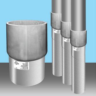
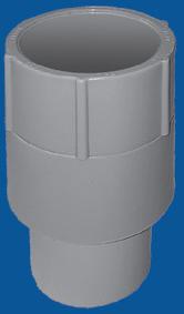
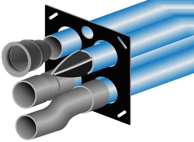
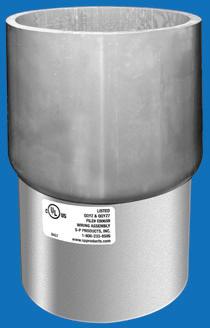
IP12 PVC Slip Transition Couplings
Reaming NOT Required
Adapters
Transition Couplings
MARKET WATCH
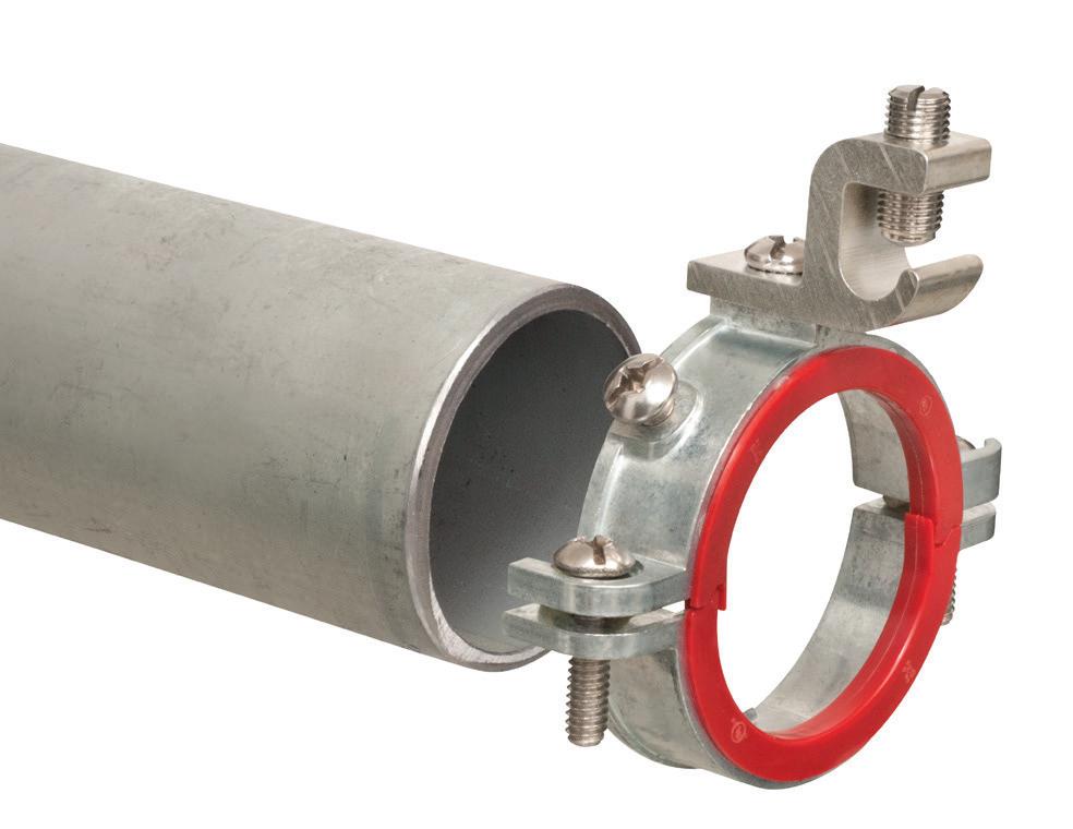
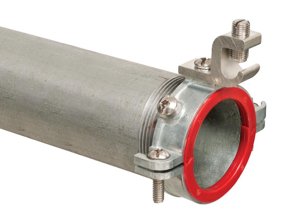
GROUNDING BUSHINGS
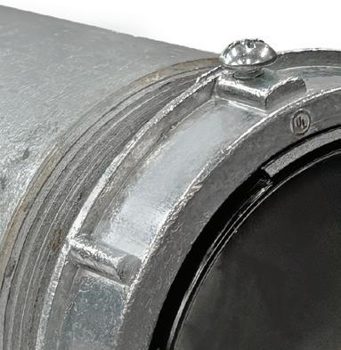
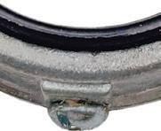
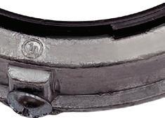
Arlington’s 450 Series zinc diecast grounding bushings are convenient and time-saving.
Our Insulated Grounding Bushings fasten and provide a secure connection for ground wiring. Fast and easy installation.
• Ships Assembled
• 1-1/4” and larger have multiple ground lug options available
• 1/2” to 6” zinc ground bushings can be used with IMC and RMC
• For Steel or Aluminum IMC or RMC
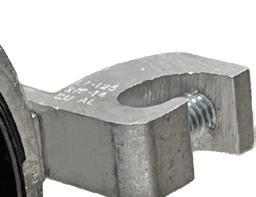
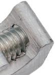
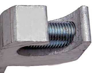
C-clamp grounding lug is dual rated for copper and aluminum.
MARKET WATCH
Construction Projects Valued at $500 Million-Plus Announced in 2026 & Now in the Pipeline
5.7%, and manufacturing starts were up 20.2% over the same period.
RESIDENTIAL SECTOR
Residential building starts grew by 2.6% in March to a seasonally adjusted annual rate of $385 billion. Single-family starts decreased 5.3% m/m, and multi-family starts expanded by 15.3% m/m. On a yearto-date basis, residential starts are down 7.2%, with single-family starts down
14.1% and multi-family starts up 6.1%.
For the 12 months ending March 2026, total residential starts fell 5.3%. Single-family starts fell 15.7% compared to the 12 months ending March 2025, and multi-family starts increased 16.3% over the same period.
The Dodge Momentum Index (DMI), which measures the three-month moving value of nonresidential build ing projects going into planning and is
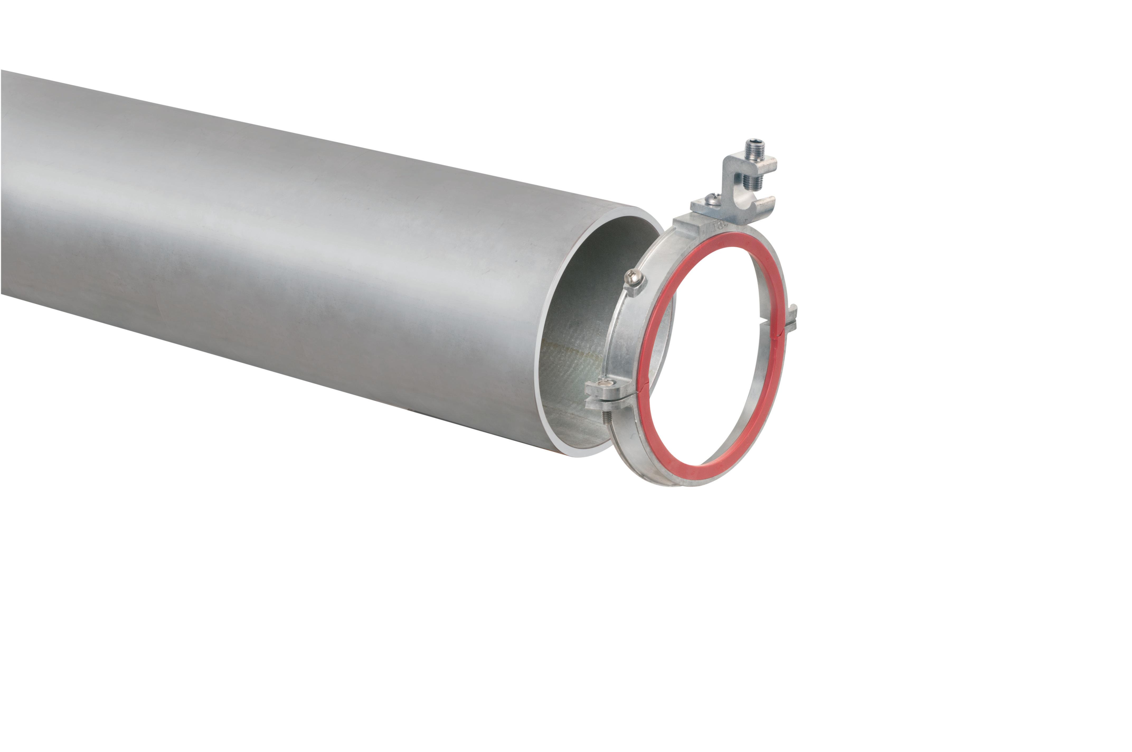
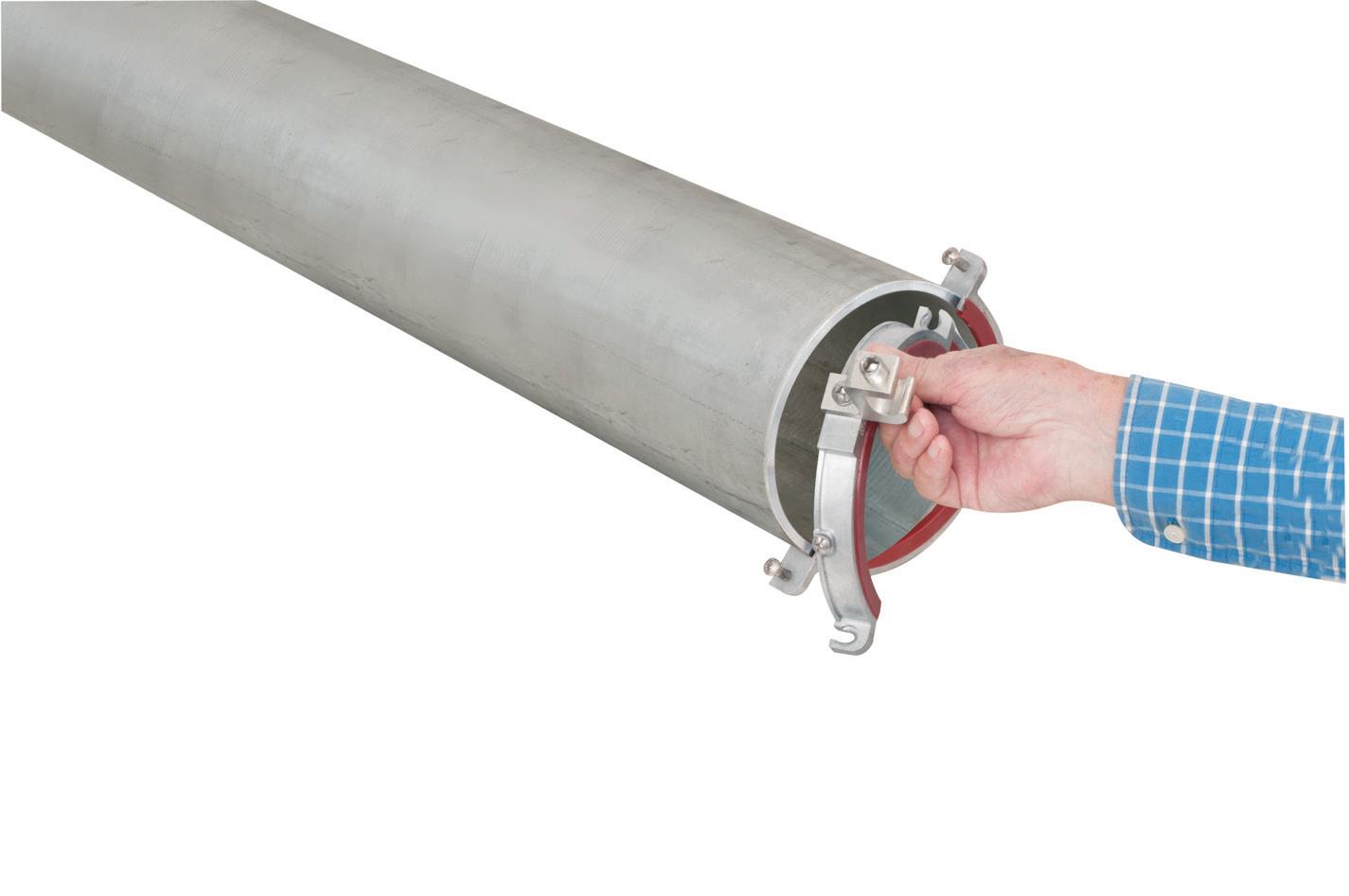
SPLIT GROUNDING BUSHINGS
EASY INSTALLATION on EMT, THREADED and UNTHREADED RIGID and IMC
Arlington’s 550 Series zinc diecast split grounding bushings are convenient and time-saving.
Available in 5” and 6” aluminum diecast
They’re split to allow the addition of a bushing BEFORE or AFTER cables are installed in threaded or unthreaded metal conduit. Great for tight spaces!
• Ships Assembled
• 1/2” to 4” zinc ground bushings can be used with IMC and RMC
• 2-1/2” to 4” zinc ground bushings can be used with IMC, RMC and EMT
• 5” & 6” aluminum ground bushings can be used with IMC, RMC and EMT
Trophy Jobs Continue to Break Ground
These mega-billion-dollar projects are now in the pipeline and should drive building activity for months to come.
Although the overall construction climate isn’t too inspiring right now in many cities and regions of the country, there always seem to be a few new mega-projects to capture the imagination of construction professionals.
Data center campuses continue to increase in scale, led by the plans of Oracle and OpenAI to build the $16.5-billion Project Jupiter data center campus in southern New Mexico and Microsoft’s January 2026 proposal for a $13-billion campus that would include 15 data centers in Mount Pleasant, Wis.; Amazon’s February 2026 announcement for a $12-billion multi-site data center campus in Caddo and Bossier Parishes, La; a $10-billion Meta data center campus in Lebanon, Ind; and Penzance’s plans announced this month for a $4-billion data center in Falling Waters, W.Va. In the Table on pages 18 and 20, 14 of the projects valued at $500 million or more are data centers, which is a pretty solid indicator that they will continue to dominate the construction market in the near future.
Other projects that made news over the past few months include the $10-billion Starr Vegas Development sports and entertainment district on the drawing boards for downtown Las Vegas; the $5-billion in planned and on-going construction at the Minot Air Force Base in Minot, N.D.; the $1-billion expansion of Miami International Airport; a $750-million soccer stadium for the Chicago Fire FC soccer team in
easing back,” said Sarah Martin, associate director of forecasting at Dodge Construction Network. “For some categories, this reflects a natural reset after the outsized growth in late 2025. But for others, elevated macroeconomic risks are likely beginning to feed into planning decisions.”
On the commercial side, planning momentum slowed across all commercial sectors apart from data centers. Institutional planning saw widespread weakness, with only education and public buildings moderately gaining traction. Despite recent declines, the DMI remains elevated. The DMI was up 25.8% YOY when compared to March 2025. The commercial segment was up 28.5% (-12.7% when data centers are removed), and the institutional segment was up 19.6% over the same period.
A total of 54 projects valued at $100 million or more entered planning
Chicago; and Rowan University’s innovative $690-million West Campus Development Project in Glassboro, N.J. The project includes an integrated district for health and manu facturing innovation that would tap into the school’s focus on health care and advanced manufacturing. Features of the project include multi- and single- family housing, a retire ment community, a hotel and conference center, medical offices, and a manufacturing center that would include R&D labs, a virtual reality center, and manufacturing space for private companies.
Another large project that made headlines is the new American Express headquarters planned for part of the old World Trade Center site in lower Manhattan (see page 16). While the company did not release the project’s total contract value, it will easily be one of the largest office proj ects in the nation. The 55-story office tower will be 1,226-ft tall and include 2 million square feet of space. The company said the building’s capacity would be up to 10,000 workers and is expected to be completed by 2031.
Arizona State University also has plans for two interesting projects — the $187-million John S. McCain III Library and Museum, which had a ceremonial groundbreaking on the uni versity’s Tempe, AZ, campus in January, and the $200-million Arizona State University Health Building, expected to start construction in July 2026, approximately 12.6 miles west of nearby downtown Phoenix.
throughout February. The largest of those projects included 17 individual buildings, each valued at $500 million, for the Amazon Data Center Campus in Hamlet, N.C. Similarly, 10 individual buildings, each valued at $250 million, entered planning in relation to the Microsoft Data Center DSM50 project in Dallas, Iowa. The largest institutional construction projects were the $245-million MCLJ Outpatient Pavilion in San Diego, Calif.; the $183-million Orlando Health Viera Hospital (Phase 1B) in Viera West, Fla.; and the $175-million Bachelor Enlisted Quarters renovation project at Camp Pendleton North in San Diego, Calif.
NONBUILDING SECTOR
Nonbuilding construction starts jumped 37.9% in March to a seasonally adjusted annual rate of $369 billion. Three mega-projects continued the flipflopping streak in the electric power/
utilities segment, which popped up 353.6% m/m in March. Miscellaneous nonbuilding increased as well, rising 44% over the month. Conversely, highways and bridges (-13.6% m/m) and environmental public works (-4.1% m/m) reversed gains from the previous month. On a year-to-date basis through March, nonbuilding construction was up 6.4% alongside the year-to-date growth in electric power/utilities (+68.6%). The remaining public works sectors, however, are seeing deeper year-to-date declines.
For the 12 months ending March 2026, total nonbuilding starts were up 15.8%. Environmental public works fell by 6.4% compared to the 12 months ending March 2025. Highway and bridge starts were down 1%; miscellaneous nonbuilding starts were up 34.9%; and utility/gas starts increased 52.3% over the same period.
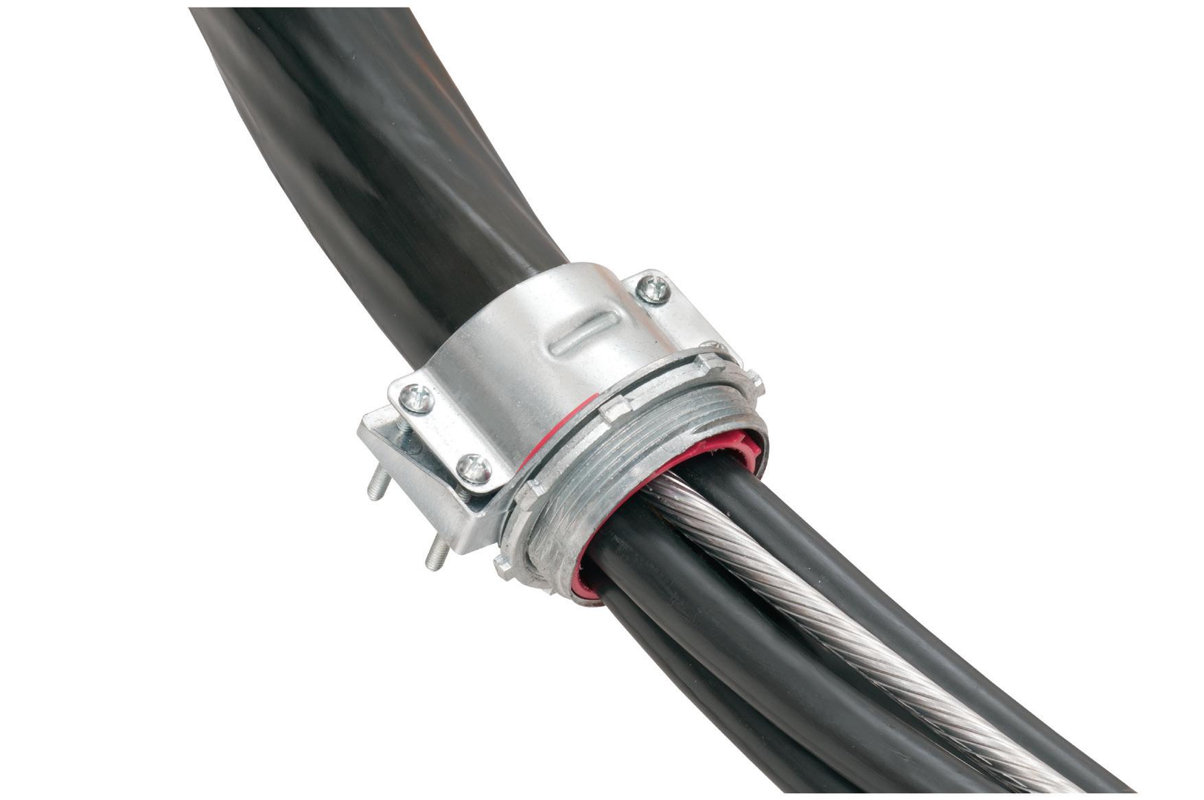
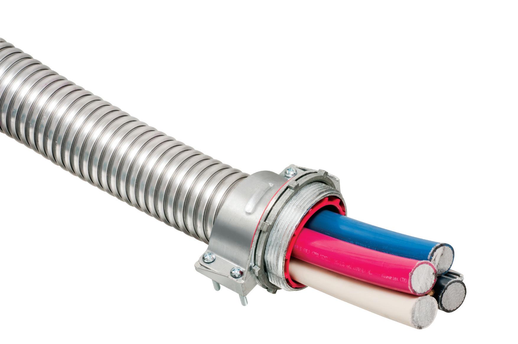
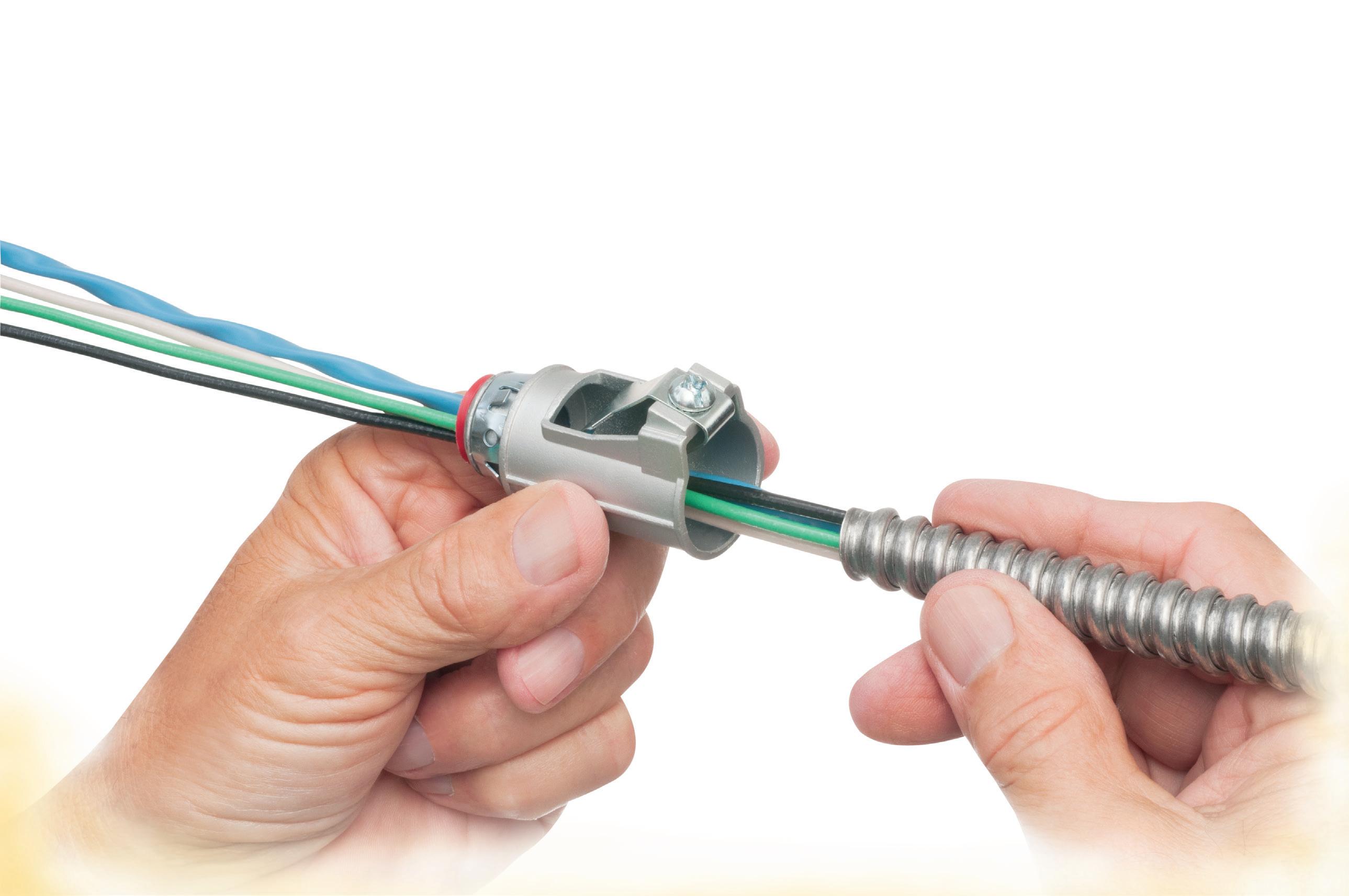
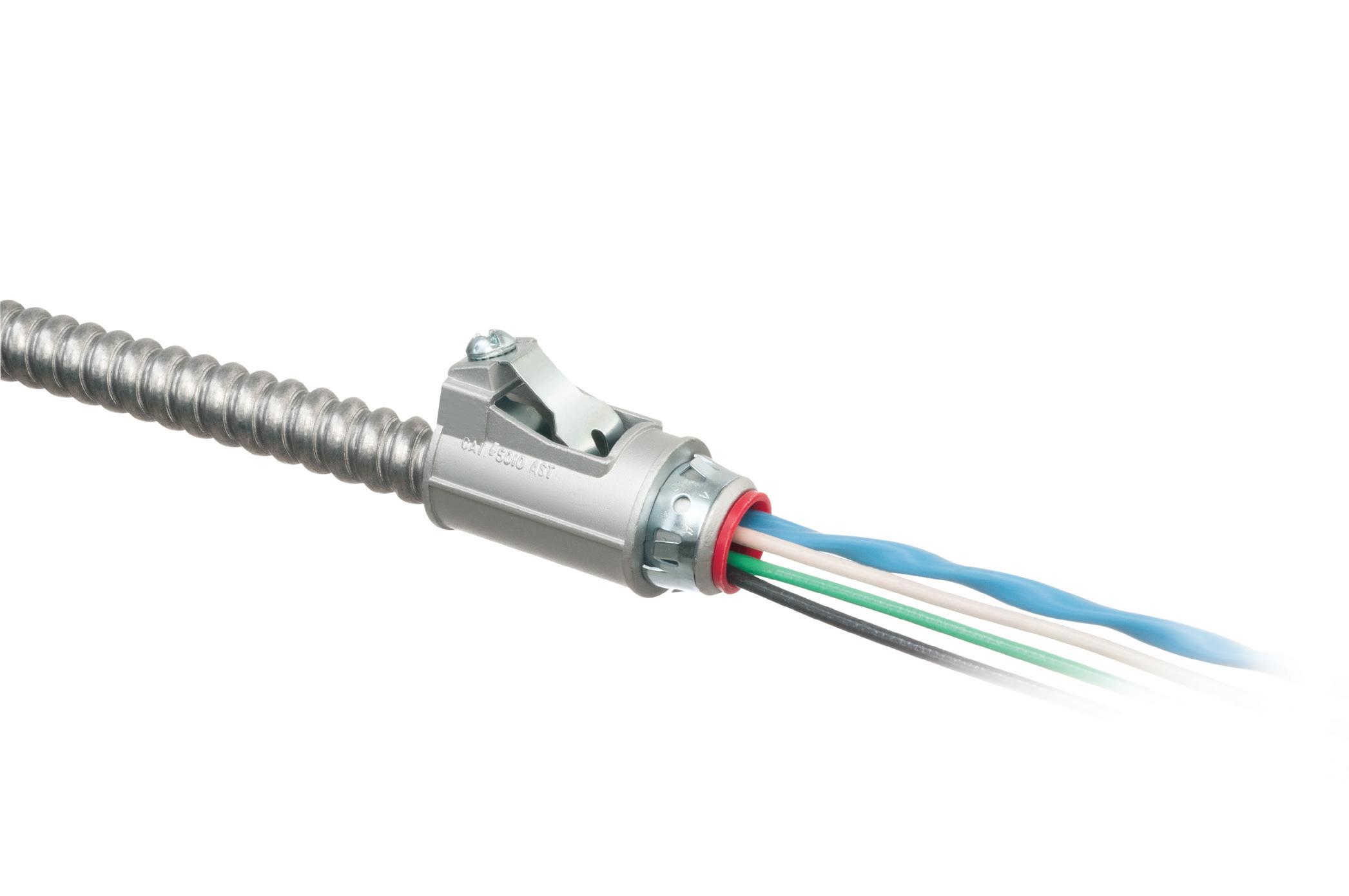
MC CABLE FITTINGS
ONE FITTING FITS MULTIPLE CABLE/CONDUIT TYPES & SIZES
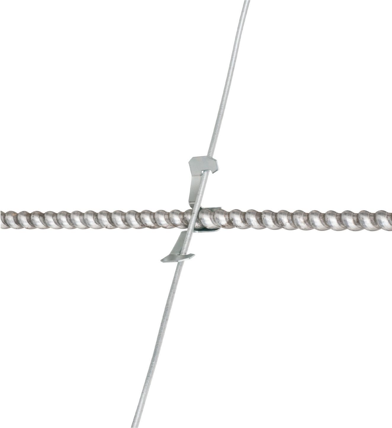
* Aluminum & Steel Flexible Metal Conduits
ONE trade size fits SEVERAL cable types and sizes, plus flexible metal conduit for super convenience and cost-savings! Reduces inventory and material handling too.
How to Determine the Most Effective Fall Protection Solution on Job Sites
A thorough understanding and implementation of the hierarchy of fall protection controls can help protect workers from fall-related injuries and fatalities.
By Philip Jacklin, Diversified Fall Protection
According to federal OSHA 1910 General Industry standards, employers are legally mandated to provide fall protection to employees whenever they are exposed to a fall hazard of 4 ft or greater. In the OSHA 1926 Construction standard, the trigger height requiring fall protection was raised to 6 ft or greater. At those heights, OSHA will deem safety netting, guardrail, and personal fall arrest systems as equally compliant solutions.
Most safety professionals will confirm that not all fall protection systems are created equal. Some (like guardrails) are extremely simple, while others (like horizontal lifelines) can require extensive engineering to install and present a steep learning curve for experienced and inexperienced users alike. The more complicated the system, the more likely misuse and accidents can occur. Equipment misuse and accidental falls are the prevailing conditions that lead to workplace tragedies.
Each fall hazard in a facility or job site must be evaluated to determine the fall protection solution that provides the highest protection factor for the worker. However, ease of use should also be considered. This article will discuss various types of fall protection solutions and describe how effective each solution is at preventing injuries or fatalities.
HIERARCHY OF FALL PROTECTION CONTROLS
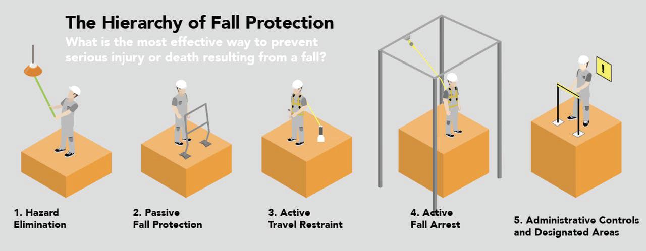
When a fall hazard is identified, the parties responsible must determine which solution is most applicable for the situation. Many industry experts refer to the hierarchy of fall protection controls (Figure on page 26) for guidance. The hierarchy ranks fall protection solutions from most effective to least effective regarding preventing injury or fatality to the worker. Hazard elimination sits at the top of the hierarchy because removing a fall
hazard eliminates the chance of a fall occurring, which obviously prevents an injury from a fall. Moving down the hierarchy increasingly exposes the worker to the risk of falling, thus steadily increasing the chances of injury and, ultimately, fatality.
This is not to say that hazard elimination is the most ideal fall protection solution for every fall hazard because eliminating hazards may be impossible or infeasible in certain environments, especially in construction. Nevertheless,
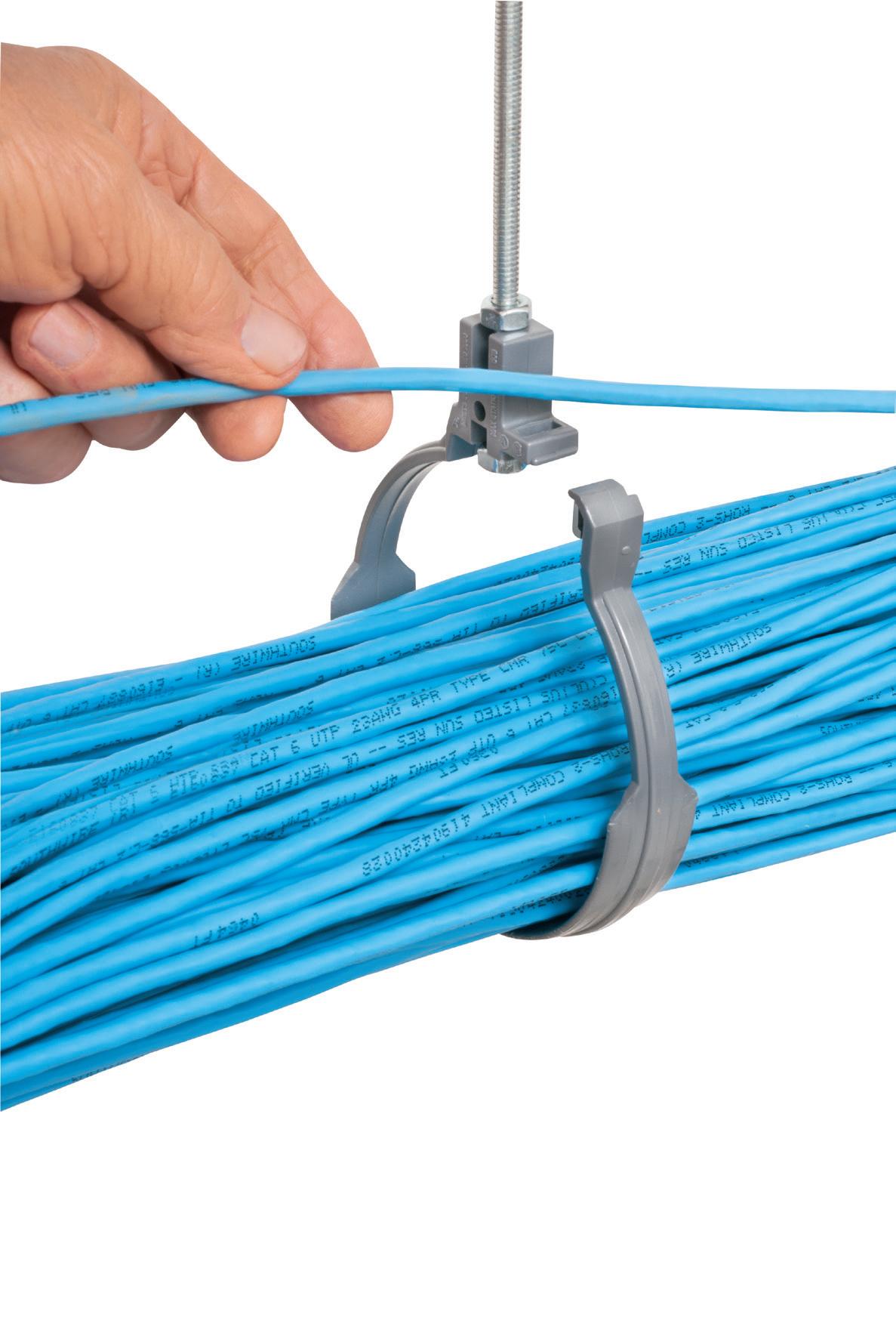
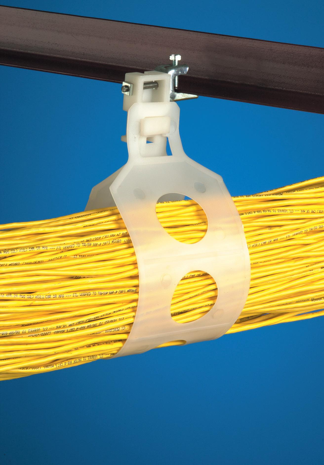
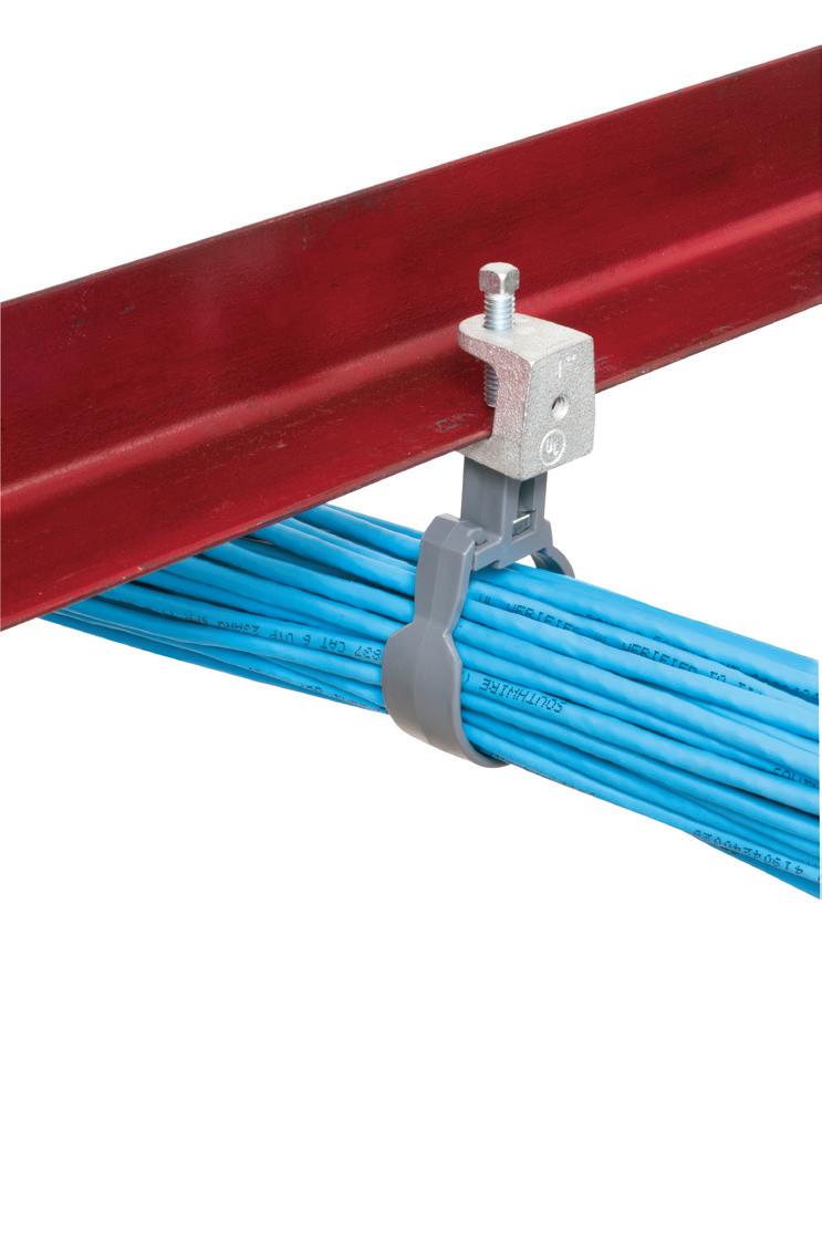
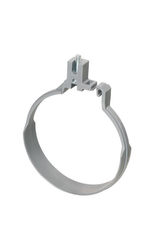
Flexible, non-metallic, The LOOP® holds a 2" to 5" diameter bundle of CAT 5 or fiber optic cable without sagging, bending or damaging the cable!
Single or multiple LOOP hangers mount in a variety of ways and rotate to any angle.
The 2.5" TL25 holds the same amount of cable as a J-hook at 1/2 the COST!
The HOOP™ is easy to use – and its smooth, non-metallic surface protects MC/ AC and NM cable against damage. No bending or kinking!
Plus, it offers versatile mounting Horizontal or vertical ON a beam clamp, wood beam or threaded rod – or UNDER a
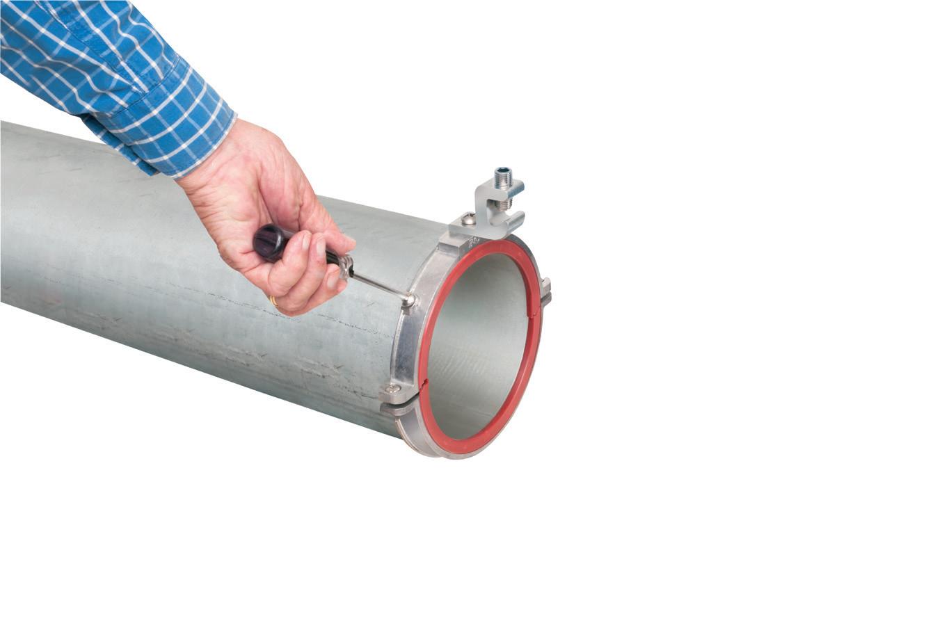
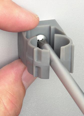
• To add cable use a screwdriver to open
EYE ON SAFETY
This hierarchy ranks fall protection mitigation tactics from most to least effective.
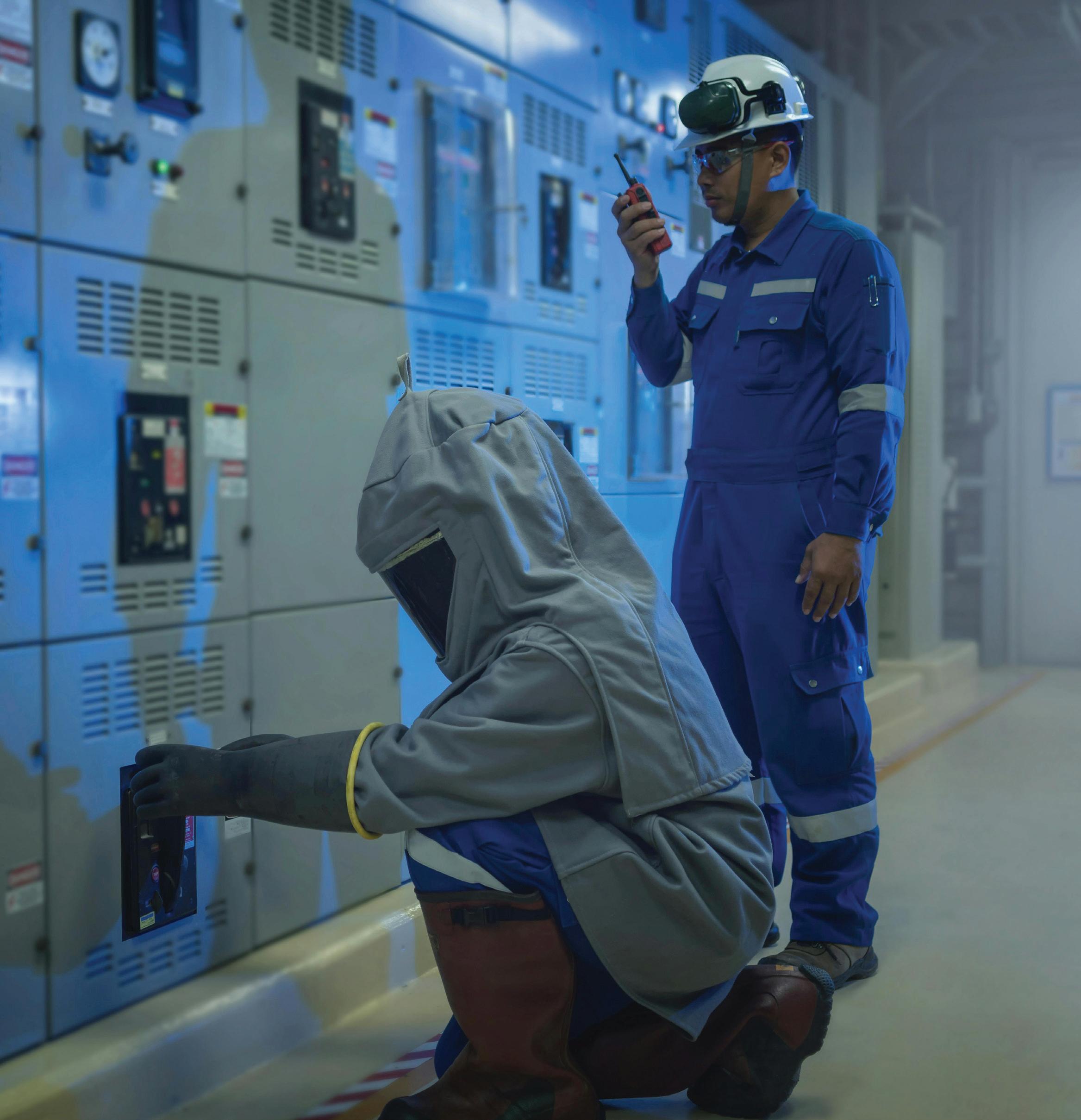
when preventing injuries and fatalities is the ultimate goal of a fall protection program, it is always worth practicing the mental exercise of figuring out how hazard elimination would even be possible, infeasibility aside. Every employer should strive not only to meet minimum OSHA standards but also to find solutions that prioritize keeping workers protected from harm.
PASSIVE FALL PROTECTION
When hazard elimination is deemed impossible or infeasible for a given hazard, the hierarchy encourages us to use the next most effective method: passive fall protection. Passive fall protection solutions are extremely effective in preventing fall injuries because they require little to no input from the user to provide protection.
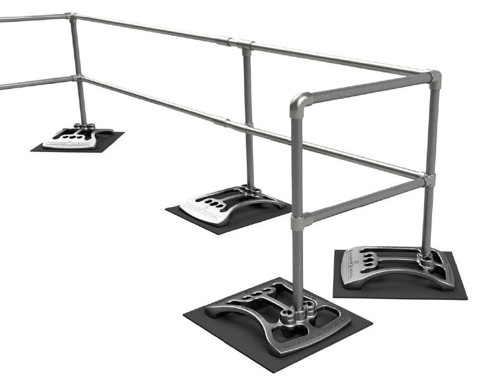
A guardrail is one of the most common examples of passive fall protection. Once a guardrail is installed on a job site, there is no inspection, certification, or training process required for users. As long as workers simply work on the correct side of the guardrail, their fall hazard is virtually eliminated from their work area. Furthermore, guardrails do not even have to be permanently installed to comply with OSHA guardrail specifications. In fact, many job sites prefer to use temporary or portable guardrails (Photo on page 28) for their ease of mobility around the job site as the project progresses and for their superior protection factor.
ACTIVE FALL PROTECTION
In many areas on a job site, guardrails may be deemed infeasible to use due to space limitations or other valid reasons. When that occurs, active fall protection solutions are next on the hierarchy. Fall restraint systems should always be attempted before using fall arrest systems. However, many job sites are
Fall arrest systems will require the most training because many factors can affect their effectiveness when a fall occurs.
wary about using fall restraint systems because they limit the working area for the tied-off worker, and many companies are unwilling to compromise productivity when other “equally compliant” fall protection solutions are available.
Fall arrest systems are extremely common on job sites, but it is important to remember that the worker will be 100% exposed to the fall hazard while working in a personal fall arrest system (PFAS). While fall arrest equipment is
intended to prevent the user from falling all the way to the next lower level, it does not guarantee injury or fatality prevention. In fact, the Center for Construction Research & Training (CPWR) reported that nearly 60% of fall fatalities occurred while the user was wearing fall protection equipment, according to a study conducted in 2021. Equipment misuse can create unforeseen vulnerabilities in fall protection systems, leading to avoidable injuries or fatalities.
TRAINING EMPLOYEES FOR PROVIDED SOLUTIONS
Fall arrest systems will require the most training because many factors can affect their effectiveness when a fall occurs. Body harnesses are not “one size fits all,” so users must know how to properly adjust their harness to their body. If a harness is too loose, the user can be ejected from the harness during a fall arrest. And if a harness is fit too tightly, it can further restrict blood flow while the user is suspended and awaiting rescue.
Minimum fall clearance requirements must be adhered to when assigning connection devices to users. That is the minimum required distance between the user and the next lower level, and the product’s instruction manual will include this information. For example, 6-ft shock-absorbing lanyards typically require at least 18 ft of fall clearance to guarantee fall arrest can occur. Users working below that height
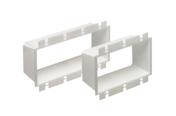
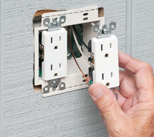
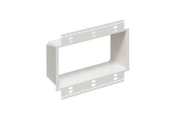
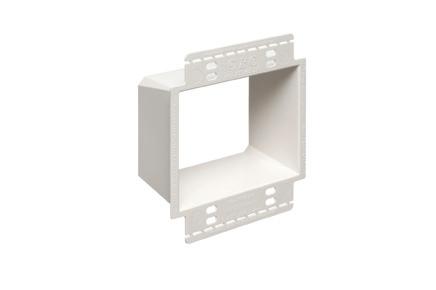
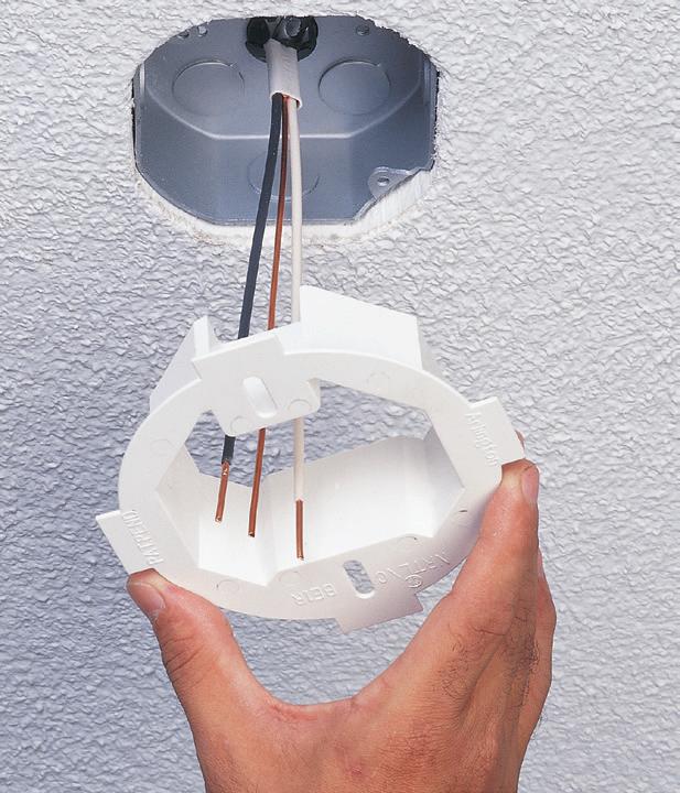
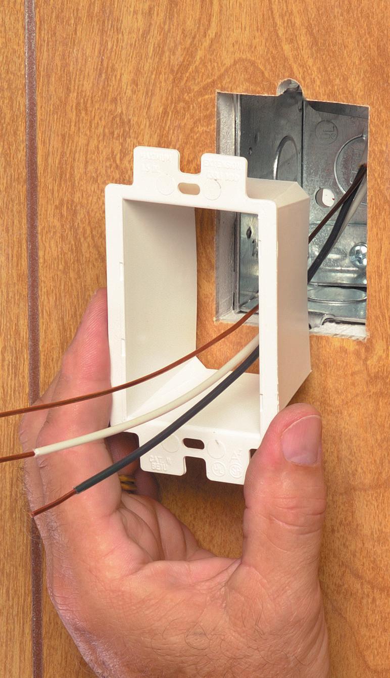
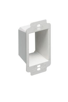
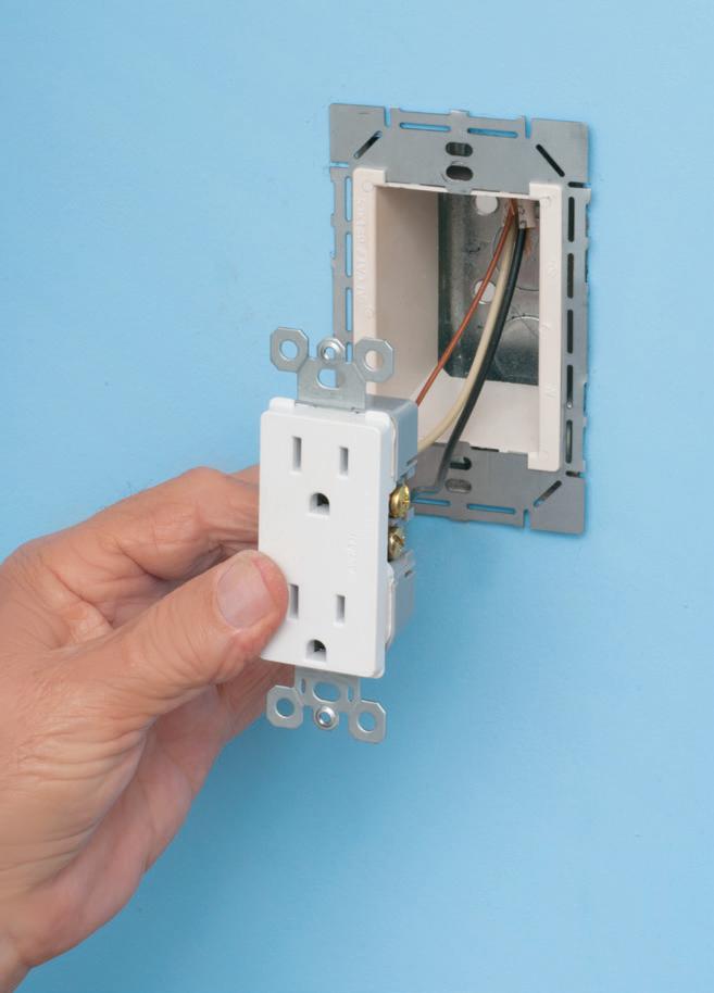
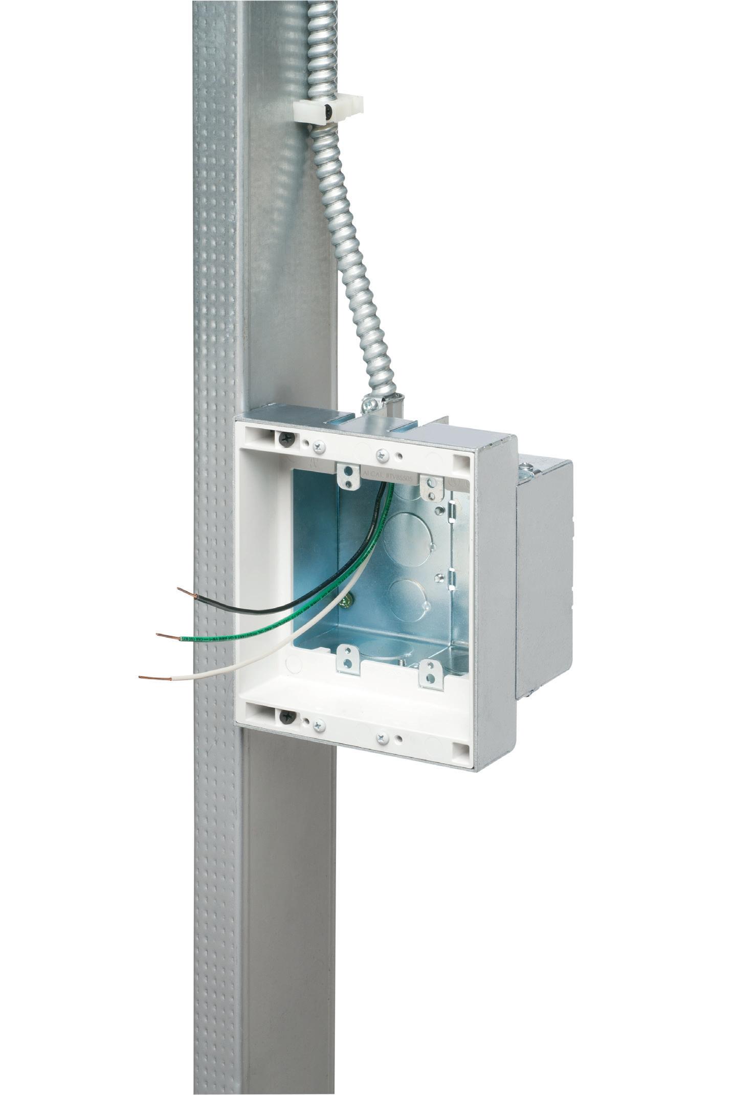
Arlington’s variety of cULus Listed Box Extenders extend set back electrical boxes up to 1-1/2”.
Made of heavy-duty, 105°C continuous use 94V0 rated, flame retardant plastic, they level and support wiring devices, while protecting wires against damage and stripping.
Choose the one that’s right for you! BE1, BE2, BE3, BE4...Single-, two-, threeand four-gang, and BE1R for round or octagonal boxes.
For all standard devices, switches and GFCIs, our box extenders comply with NEC Article 314.20 for set back boxes.
HEAVY DUTY FLANGES
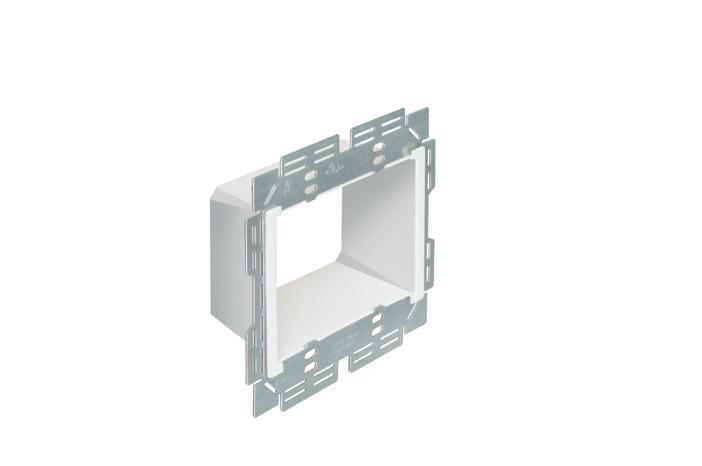
Arlington’s variety of cULus Listed Box Extenders extend set back electrical boxes up to 1-1/2”. Choose the one that’s right for you!
Box Extenders with LARGER FLANGES for better device support in oversized or mis-cut wall openings, available in single-, two-, three- and four-gang, (patented BE1X, BE2X, BE3X, BE4X.)
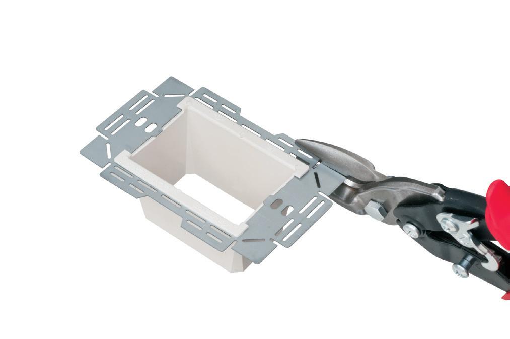
Our new heavy duty, COMMERCIAL-GRADE Box Extender with a galvanized steel support plate! As shipped, single and two-gang BE1XLS and BE2XLS work with maxi cover plates, but they’re TRIMMABLE for use with midi and standard plates. Convenient. Saves time. Great for poorly cut drywall.
For all standard devices, switches and GFCIs, our box extenders comply with NEC Article 314.20 for set back boxes.
EYE ON SAFETY
CodeWatch
This e-newsletter, published four times per month, is dedicated to coverage of the National Electrical Code. The content items are developed by well-known Code experts.
CodeWatch promises to:
• Explain how to properly apply the Code
• Test your knowledge of the Code
• Provide information on upcoming Code-related seminars and shows
• Offer Code quizzes and real-world Code violations
Subscribe Today
See all of our EC&M e-newsletters at www.ecmweb.com
example of an OSHA-compliant freestanding guardrail system.
may be at risk of contacting the ground before their fall is fully arrested. If a body in motion contacts the ground before fall arrest is complete, the user will sustain more severe injuries.
Self-retracting lifelines (SRLs) will require less fall clearance, but employers must confirm their workers are always working above the minimum clearance as specified by the manufacturer. Additionally, employers must confirm that minimum fall clearance requirements can be met before assigning certain connection devices to their workers.
No matter the fall protection solution chosen to mitigate specific fall hazards, OSHA requires employers to train workers on how to use their equipment before they can be authorized to work at heights. As stated previously, guardrail solutions will require no training because they do not require user input to be effective in protecting the worker from a fall.
CONCLUSION
Using the hierarchy of fall protection controls will help employers determine the effectiveness of their current fall protection solutions, relative to other possible solutions. As long as fall protection is provided, that usually means
an organization is headed in the right direction. However, we should always strive to make our fall protection programs more robust, more preventive, and more effective at preventing falls in the first place. If we prevent the fall, we are guaranteed to prevent the potential injury.
Fall protection programs often carry a preconceived notion that they must be intricate, sophisticated, or complicated to be effective in protecting workers. However, simple solutions that are used consistently will best protect workers. There’s a popular phrase in the safety industry that says, “The best fall protection system isn’t the most expensive; it’s the one people will use every time they work.” All efforts made to protect workers today can help prevent tragedies tomorrow.
Philip Jacklin is the Continuing Education Program Manager for Diversified Fall Protection. He is an AIA continuing ed provider, QSSP certified, OSHA-30 trained, and has been a partner to the fall protection industry since 2018. Philip has a background in worker advocacy, team leadership, and fostering camaraderie among peers. He can be reached at pjacklin@fallprotect.com.
An
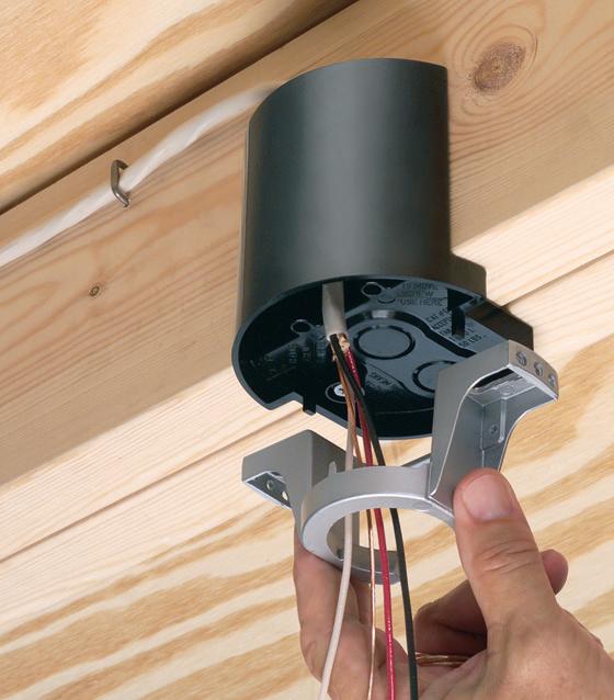
FAN FIXTURE BOX
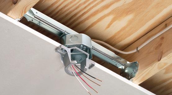
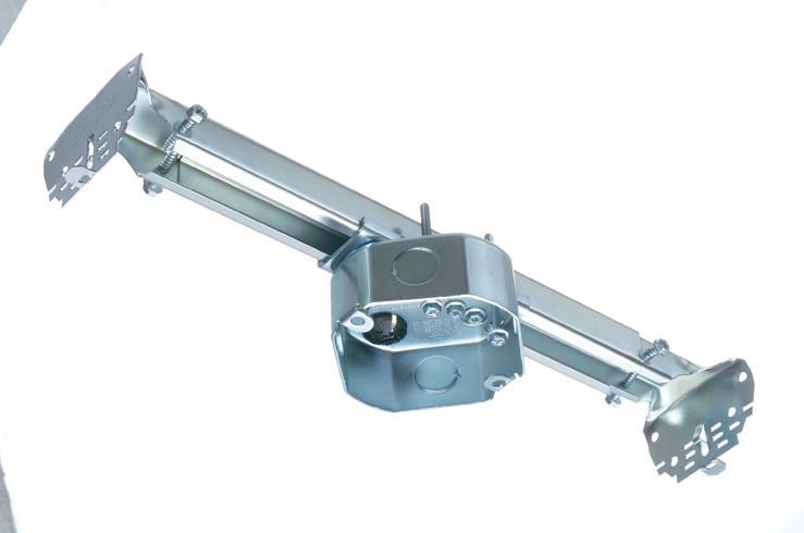
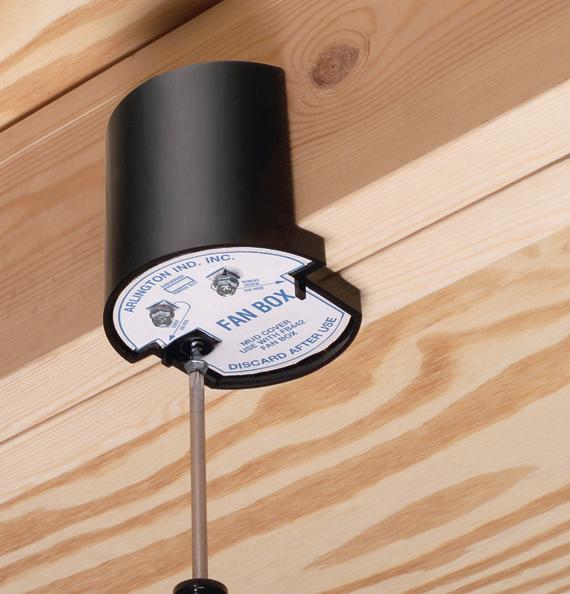
Arlington’s heavy-duty, plated steel fan/ fixture box has an adjustable bracket that mounts securely between joists spaced 16" to 24" o.c.
Flush ceiling installations
FBRS415 is designed for ceilings up to 1-1/4" thick. For 1/2" ceilings, use the pre-bent positioning tab. For other ceiling thicknesses, bend along the appropriate score line.
• 15.6 cu. inch box ships with captive screws, mud cover, installed NM cable connector
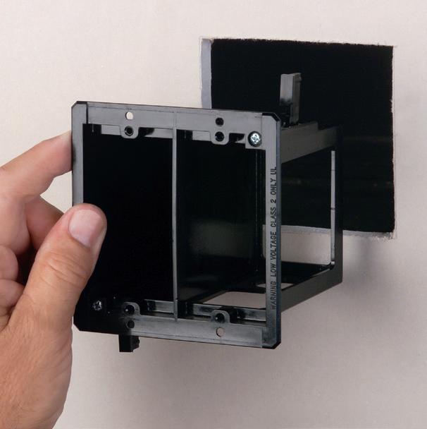
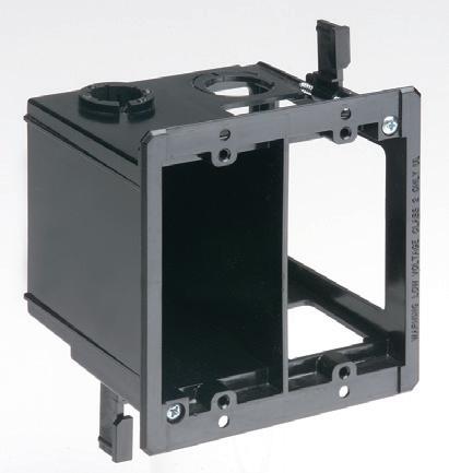
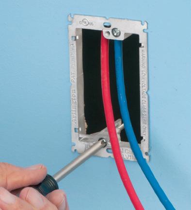
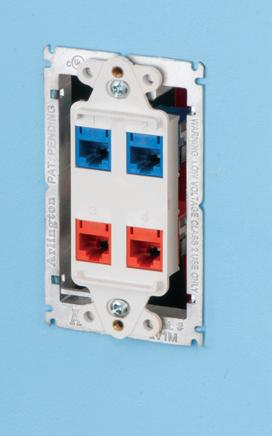
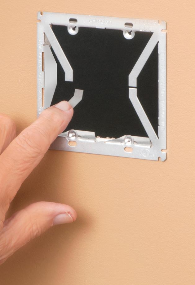
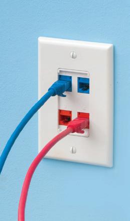
This convenient combo box has power and low voltage openings in the same box for a neat, time-saving installation.
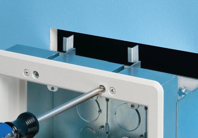
The box adjusts to fit wall thicknesses from 1/4" to 1-1/2". Mounting wing screws hold it securely in place.
• 2-Hour Fire Rating
• Low voltage side has a combo 1/2" and 3/4" KO for raceway
• Includes NM cable connector (power side)
The Path to Excellence: Skills and Attitudes of Top Electrical Technicians
Strategies for leveling up your current skillset to become the go-to electrical technician for the job
By Mose Ramieh III, CBS Field Services
For years, we have faced an unprecedented worker shortage across the electrical industry, including technicians. Because of it, it is important to not only have more skilled individuals in order to meet growing demands in services like power system maintenance, but also to focus on improving the skillsets of current technicians.
This article explores the essential qualities and actions that will transform you from just one technician of many
into the go-to technician — someone your customers and company can always depend on.
APPEARANCE AND PROFESSIONALISM: WHY FIRST IMPRESSIONS MATTER
How you show up on the job is often the first indication of your professionalism. A wrinkled shirt, untucked uniform, or disheveled appearance can undermine confidence in your abilities. A quality technician knows that presenting
yourself as polished and ready to work sets the tone for the rest of the day.
Look around. The customer naturally navigates to the sharpest-looking person in the crew even if that person is the most junior of the group. Looking sharp includes your service truck or van, and it’s frustrating to see a technician’s truck full of take-out trash or in disarray. You are busy and constantly traveling in this field, but build habits that allow you to take the time to look like the professional you want to become.
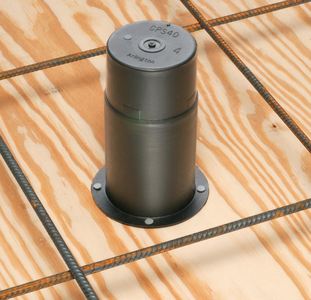
CONCRETE PIPE SLEEVE
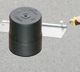
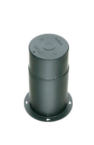
Arlington’s Concrete Pipe Sleeves are the economical way to sleeve through concrete pours in tilt-up construction WALLS – and FLOORS allowing cable and conduit to run easily from one floor to the next.
No costly core drilling – No cutting holes in the form. Plus, you can position the hole prior to pouring the concrete.
• Attaches to form with nails or screws
• Stackable up to 23" h for extra deep pours
• Vents keep wet pipe sleeves from sticking together
• Multiple hole sizes: 1-1/2"
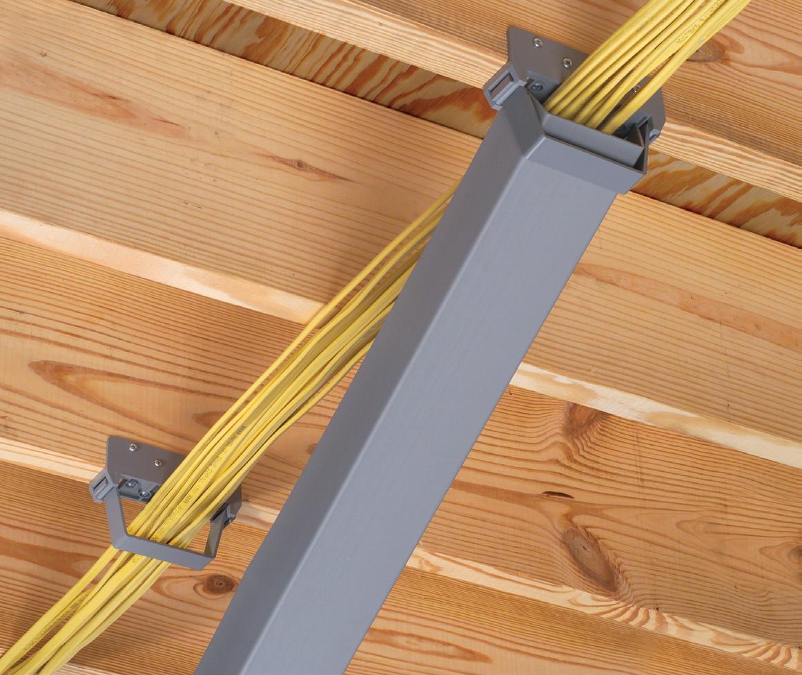
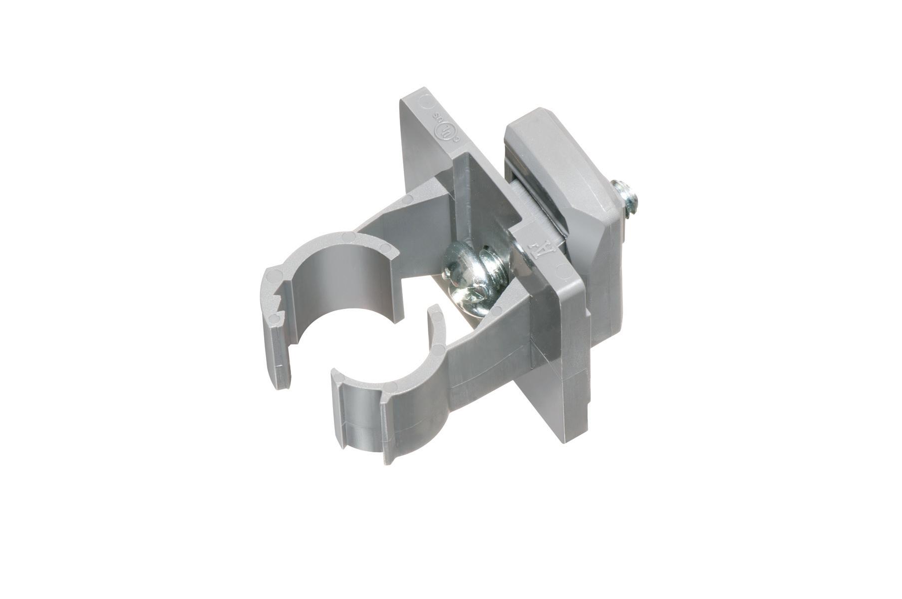
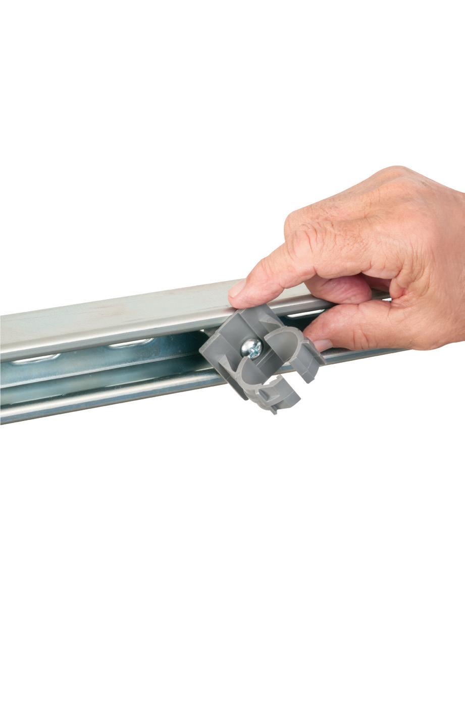
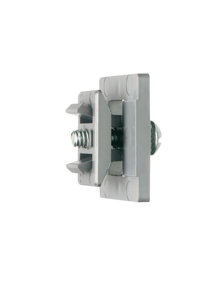
Support Brackets attach to framing members, with no structural damage. They hold cables securely in place, and open for easy cable insertion! The Slide-On Trough holds and protects cable. Add length by installing more sections joined together with Coupling Angles and Tees make turning corners a breeze.
Push-on End Caps complete the job.
CPS40
After concrete sets, cut sleeve flush with surface. Insert conduit into sleeve.
ELECTRICAL TESTING EDUCATION
REPORT QUALITY AND ACCURACY: TEST REPORTS ARE KEY
The technician understands that the test report is often the most critical deliverable for the customer. It’s not just about performing the tests; it’s also about documenting results accurately and thoroughly. Customers are paying for a high-quality, complete report, not just your time on site.
Avoid shortcuts
Completing test sheets accurately and in real time on your company’s designated electronic platform ensures no details are missed. Filling in data later or relying on scraps of paper is risky and can lead to errors, extra work, or even lost credibility. You might think you are saving time by using other methods to collect data, but it has been proven time and again that spending the extra five to 10 minutes on site to enter the data correctly saves hours after the job is over. The worst-case scenario is one where the data is incomplete, and you must revisit the site to obtain the missing data.
Use objective language
The technician uses technically accurate language when interacting with clients. Avoid slang or vague terms that can confuse or mislead. Clear communication builds trust and respect.
In reports and communications with customers, avoid subjective terms like “high” or “low” or “bad.” Subjective terms are open to interpretation and can trigger fear and concern where none need exist. Instead, provide factual statements such as, “The power factor is 2.0%, while the standard is 0.5%.” A statement that the insulation resistance is “extremely low” could be improved: “The insulation resistance does not meet the NETA minimum for the equipment rating.”
OWNERSHIP AND INITIATIVE: LEAD THE JOB
The technician doesn’t wait to be told what to do. Review the scope of work before the project begins, and be proactive in reaching out to the customer to clarify details. This kind of initiative sets the technician apart from
someone who simply follows instructions. Every company needs more technicians who can take on a project and accomplish the management and customer responsibilities. These processes vary from company to company, so know what your processes are, and do everything you can to know your customers and projects. Failure to understand the customer and project expectations creates stress and leads to poor or inefficient performance.
Continuous learning
Whether through books, articles, podcasts, or videos, the technician always seeks opportunities to learn. Technical skills are vital, but so is personal development. Keep asking, “What more can I do?”
TOOL AND EQUIPMENT MAINTENANCE: TEST EQUIPMENT
The technician understands that proper maintenance and care of your tools is critical. Ensure that equipment is
Electrical Testing Education articles are provided by the InterNational Electrical Testing Association (NETA), www.NETAworld.org. NETA was formed in 1972 to establish uniform testing procedures for electrical equipment and systems. Today the association accredits electrical testing companies; certifies electrical testing technicians; publishes the ANSI/NETA Standards for Acceptance Testing, Maintenance Testing, Commissioning, and the Certification of Electrical Test Technicians; and provides training through its annual conferences (PowerTest and EPIC — Electrical Power Innovations Conference) and its expansive library of educational resources.
stored, transported, and used correctly. Damaged equipment doesn’t just cost the company money — it impacts your ability to do your job effectively. Treat equipment with care. While it was designed to be rugged, mishandling, standing on leads, or exposing equipment to weather will cost you money.
Don’t normalize deviation
Don’t allow poor practices like damaged leads or malfunctioning equipment to become normalized. We all have a piece of test equipment where you must turn the knob just right to get it to work. Always aim for optimal performance from your tools.
COACHABILITY AND LEARNING: BE OPEN TO FEEDBACK
The technician recognizes that even the most experienced technician can improve. A coachable attitude — being open to advice and willing to learn — fosters growth and ensures you are always evolving in your role.
For example, I was managing an outage, making the rounds to check on everyone’s progress. I stopped at the high-current test set where a technician reported that several breakers did not pass on short-time pick-up. When I asked questions about his method, this veteran technician wasn’t offended. He simply stepped out of the way and asked if I would show him a better way. He took my coaching and improved his technique, and breakers began to meet the manufacturer’s criteria. This experience showed me another way you can recognize who the best technicians are.
Learn through observation
The technician is curious and takes every opportunity to observe more experienced technicians, especially during challenging situations. Their problem-solving and communications with customers are valuable learning moments.
Especially during my early years in the industry, I shadowed more senior technicians when it was time to energize equipment after an outage. While others sat at the truck waiting to be released to go home at the end of a long day, I stayed close and watched the troubleshooting
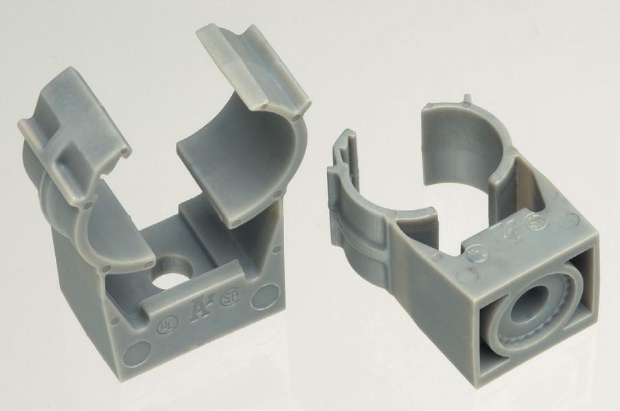
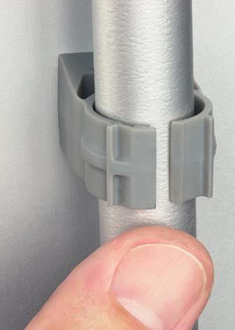
Arlington’s corrosion-resistant QUICKLATCH™ pipe hangers cost the same as a steel pipe hanger with a bolt and nut – but better. They’re faster and easier to install. And SAVE 25 seconds* per installation!
• UV rated for outdoor use
• Listed for environmental air handling spaces
• For thin walls, rigid conduit, PVC conduit or copper
ELECTRICAL TESTING EDUCATION
skills these veterans employed to work through issues and calm the customer. These lessons were invaluable, and I employ these processes to this day.
COMMUNICATING CHALLENGES: WHY BAD NEWS CAN’T WAIT
When things aren’t going as planned, communicate immediately. The technician knows that waiting to report issues — or hoping they’ll resolve themselves — often leads to bigger problems. Transparency is key in managing expectations and finding solutions. There have been too many situations where the call comes too
a personal or business problem and been unable to find a solution until you share it with a friend or coworker and the answer seems to magically come to you? Activating the language areas of the brain and being forced to break down the problem helps us find solutions.
PROBLEM SOLVING AND PERSISTENCE: EMBRACE CHALLENGES
The technician sees challenges as opportunities to grow and solve problems. Whether it’s finding the right part or figuring out a new testing procedure, the ability to preserve and solve issues
When things aren’t going as planned, communicate immediately. The technician knows that waiting to report issues — or hoping they’ll resolve themselves — often leads to bigger problems.
late to take corrective actions. Whether it is poor test results or not having the tools you need, the best time to communicate those issues is now. You might only need a second set of eyes or someone who can work out the logistics of getting the tools to get the job accomplished.
An issue we could have avoided happened when an overnight breaker testing crew failed about half of the 40 breakers they tested that night. If the technicians had recognized that a 50% failure rate was off and called me, we could have worked together to identify that they were not properly defeating thermal memory on the breakers.
Seek help when needed
One sign of a dependable technician is knowing when to reach out for support. Troubleshooting sometimes requires input from others — whether it’s figuring out why breakers are failing, handling complex procedures, or articulating the challenge.
Thinking about an issue doesn’t tap into all of your problem-solving resources. Have you ever struggled with
creatively is invaluable. Persistence coupled with calling for other support (like the last example) is a true mark of the technician.
Say yes more often
Instead of focusing on why something can’t be done, ask how it can be done. Whether it’s taking on additional tasks or figuring out logistical challenges, the technician has a can-do attitude that is essential for success when things get tough.
Keep it simple
The technician knows when to keep it simple. Yes, there are complicated and complex situations and electrical theories in our industry. In my experience, the simple answer is often the best.
During a hot summer in Nashville, we received a call from a facility that was attempting to meet a power reduction initiative by running a standby generator. Our company was called in when the generator transfer switch would not connect the generator to the load. While I watched the senior technician
and customer pour over drawings, I stood back and took in the controls on the transfer switch. I noticed that a switch labeled No-Load Test and Load Test was in the No-Load Test position. I suggested that perhaps the switch should be placed in the Load Test position. After a brief discussion, we moved the switch to the Load Test position, and the transfer switch transferred and connected the generator to the load. Problem solved.
TIME MANAGEMENT AND FOCUSING ON DOING TASKS NOW
Whether it’s completing a report, having a conversation with a customer, or preparing for a job, the technician knows the best time to act is now. It is tempting to think, “I can get that task done tomorrow.” Inevitably, the universe will respond to your delays by providing an emergency job or some other unplanned urgent need. Procrastination leads to increased stress and more complex problems later. Act immediately whenever possible.
Make use of downtime
Use your spare time wisely. The technician stays active. If you’re not on a job site, practice using test equipment, study manuals, or perform maintenance on your test equipment. Constantly improving your skills makes you more valuable to your team.
The technician knows that preparing for a project before it’s time to go on site can save both time and money. Research published by the Construction Industry Institute has shown that front-end planning leads to added project value. Benjamin Franklin may have said it best: “By failing to prepare, you are preparing to fail.” This could be as simple as creating a load list of the equipment you need for the job or as complicated as creating a Gantt chart to track all tasks.
One of my favorite preparation tasks is the prepopulating of test sheets. Getting as much customer information and equipment designations on the test sheet before the job further minimizes the urge to take shortcuts when completing test sheets in the field and creates consistency of information between multiple teams.
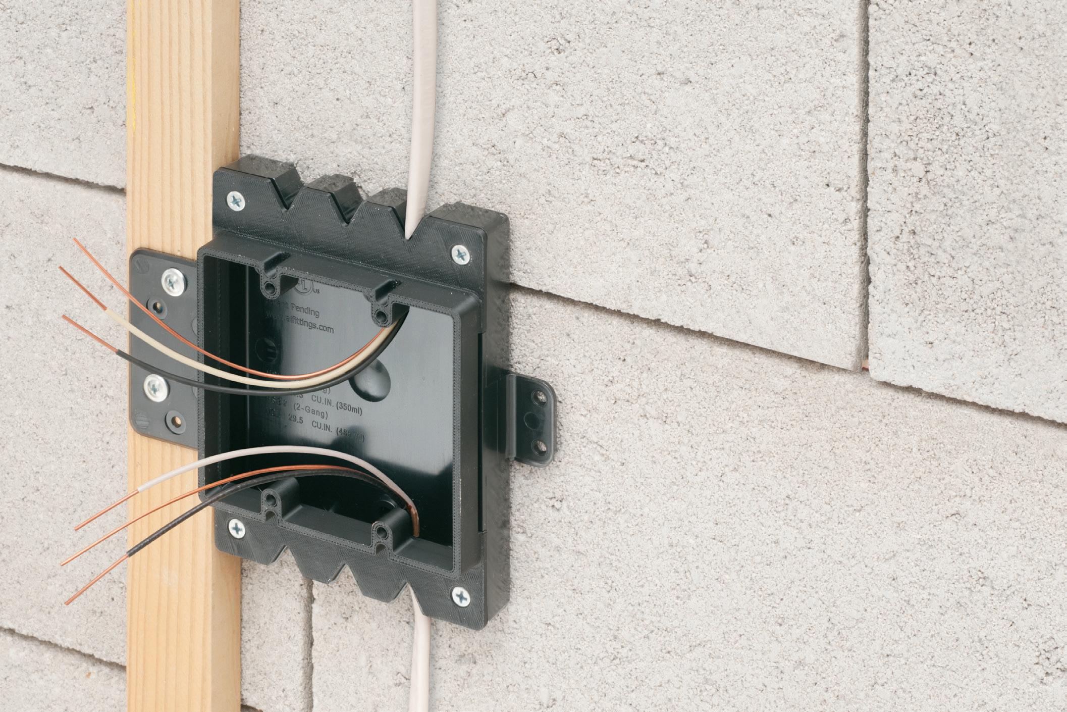
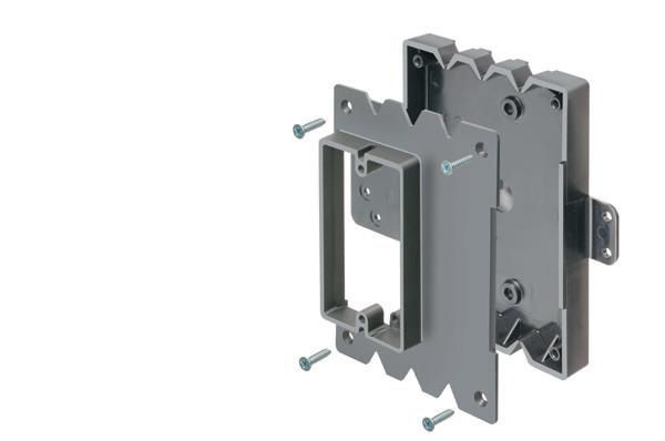
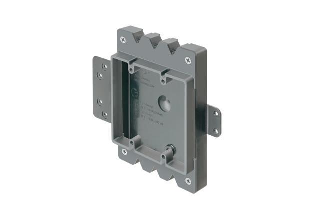
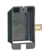
Our NEW Low Profile single and two-gang Furred Wall Box™ base assemblies have a 1/2” raised box cover for use with 1/2” wall thickness and standard depth devices.
Fast, easy installation. There’s NO NEED to break out concrete block. NO NEED to install separate furring strips. NO NEED to seal the block wall breakout and box.
• Integral cable securement – No pullout!
• Versatile mounting options - installers can place the box/outlet where it’s needed.
• Add BE1 or BE2 Box Extenders for applications with > 1/2” to 1-1/2 wall thickness
• Add BES1 or BES2 Surface Box Extenders for applicatoins with deep GFCI or USB oultet and 1/2” wall thickness
ELECTRICAL TESTING EDUCATION
ADAPTIBILITY AND EMBRACING CHANGE
Industries evolve, and so do company structures and technologies. The technician is adaptable. When change comes, view it as an opportunity to learn and grow.
Maintain high ethical standards
The technician is always honest in their work. Whether it’s reporting data accurately or admitting when a mistake has been made, integrity builds long-term trust with your company and customers. Mistakes happen to the best of us. There is a running joke in the electrical testing industry that there are only two types of technicians: those who have caused an unplanned outage and those who will cause an unplanned outage. When your time comes and you need to explain what happened to create an outage, be transparent and humble. Any attempts to cover up an event or deflect your participation in the outage will follow you in your career.
I was working in a utility substation during one such occurrence when I inserted a PK block to restore a bus differential circuit. Inserting the block shorted the CTs — only for a moment — but that was all it took for the relay to operate and shut down the entire industrial sector of this small town in Tennessee. I immediately realized my mistake and was very embarrassed. It took several minutes to restore power, and once things were returned to service, I spent several hours in meetings, presenting the data outlining the errors as well as plans to prevent additional events. The ownership my company and I took in the error further deepened our relationship with the client.
Another note about ethics: This also applies to how you document your expenses and track your time. The technician does not look for ways to work the system because they understand that how you do anything is how you do everything.
CONCLUSION
Becoming the best technician you can be isn’t about having more technical knowledge than others — it’s about how you approach your work, your relationships inside and outside the company, and your growth. By focus ing on professionalism, accuracy, initiative, care, and ethics, you become someone who is not only trusted but also relied upon by your company and your customers. The technician is more than just a job title — it’s a com mitment to excellence. Be engaged, stay positive, and treat everyone with trust and respect.
Mose Ramieh III is vice president, busi ness development at CBS Field Services and has been in the electrical testing industry for 26 years. He is a Level IV NETA Technician with an eye for sim plicity and utilizing the KISS principle in the execution of acceptance and mainte nance testing.
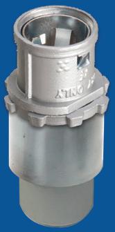
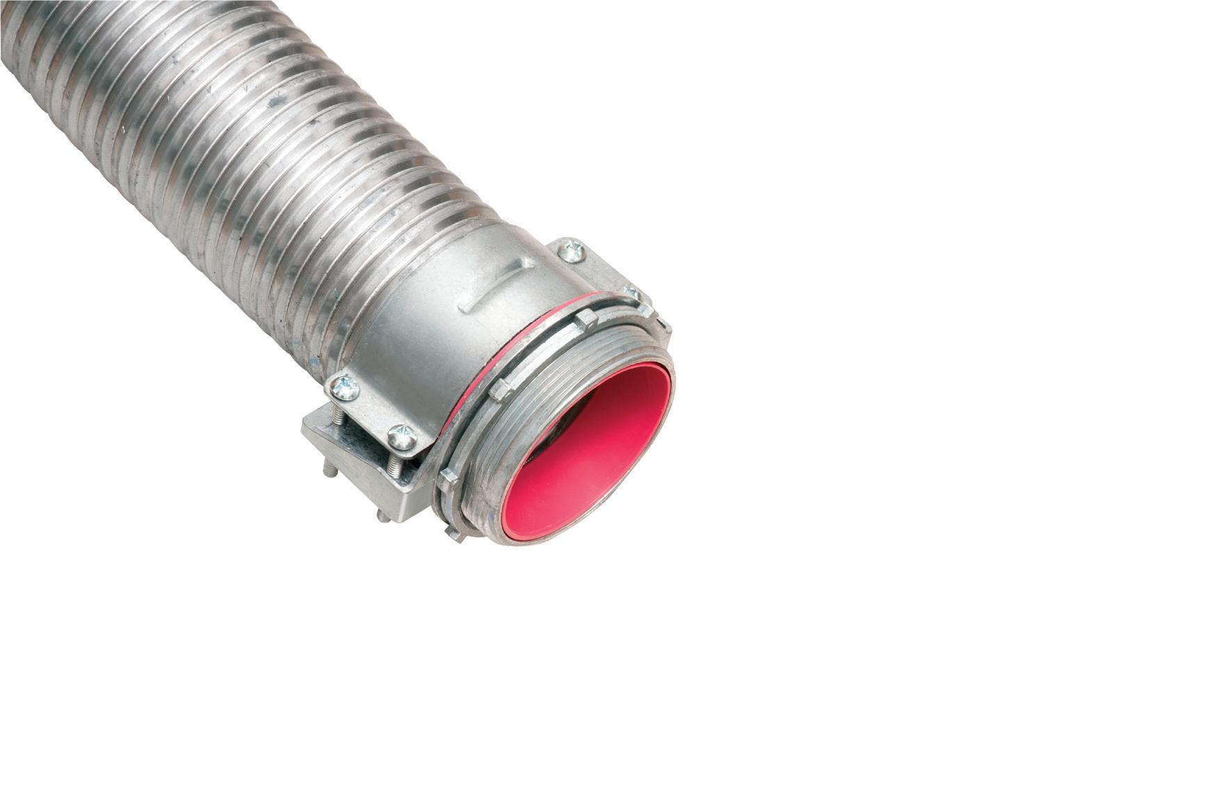
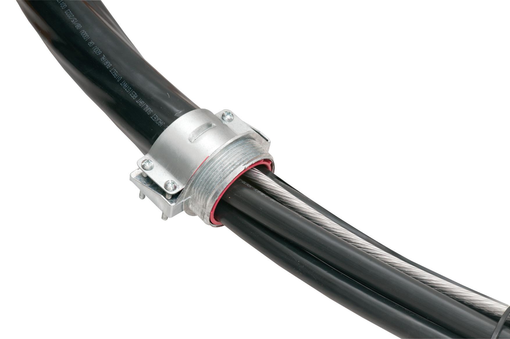
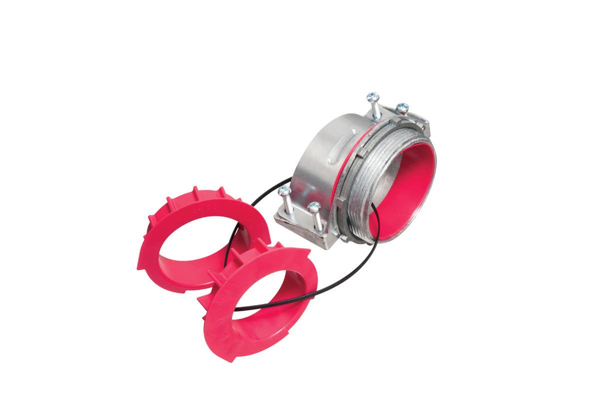
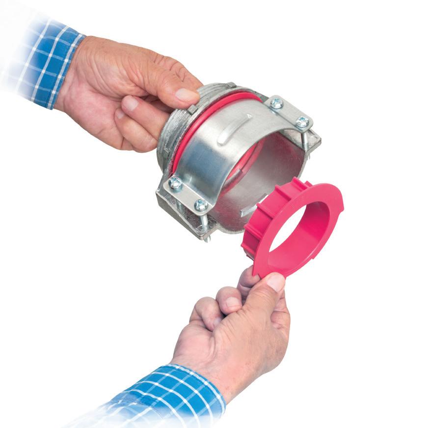
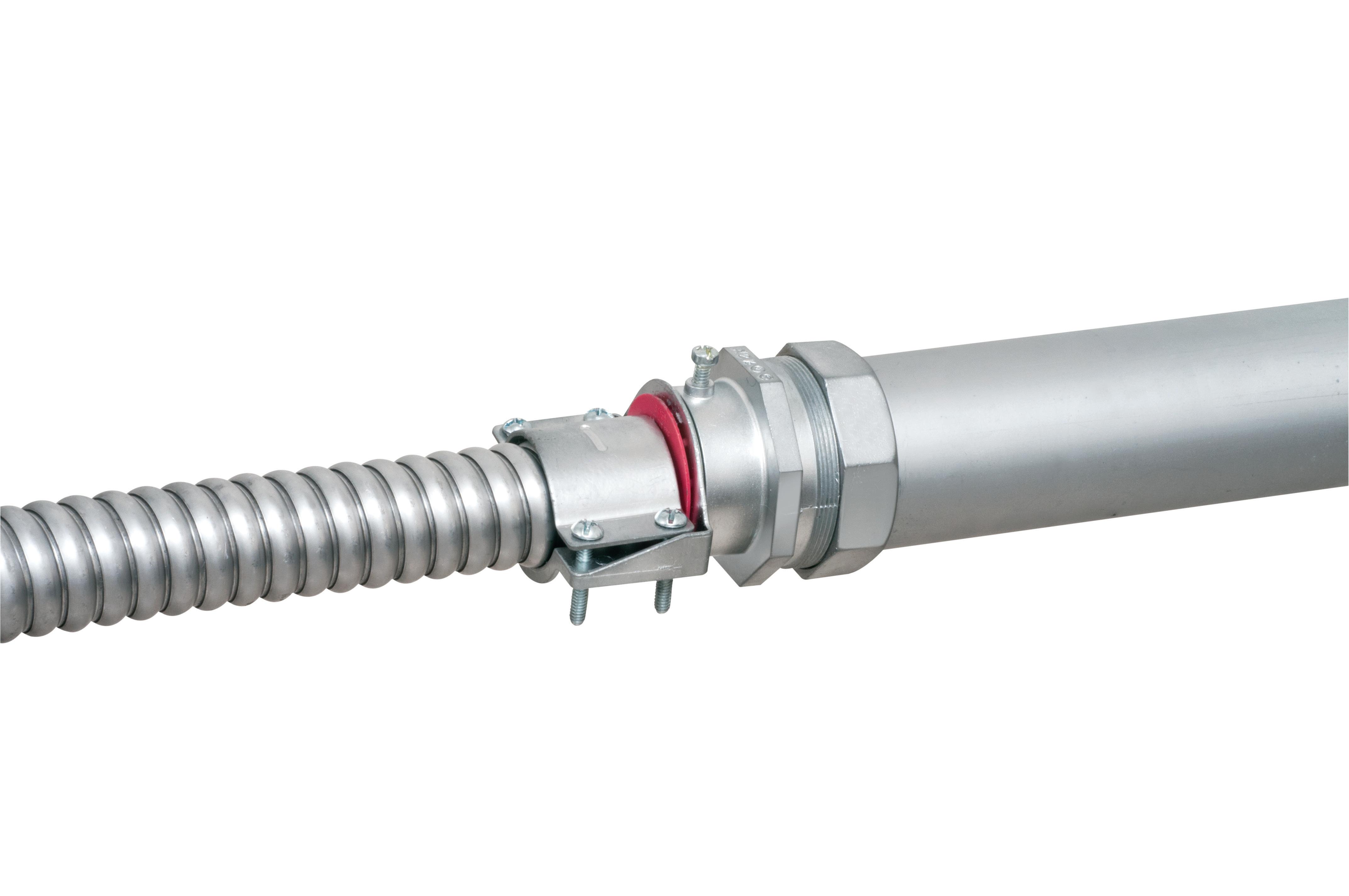
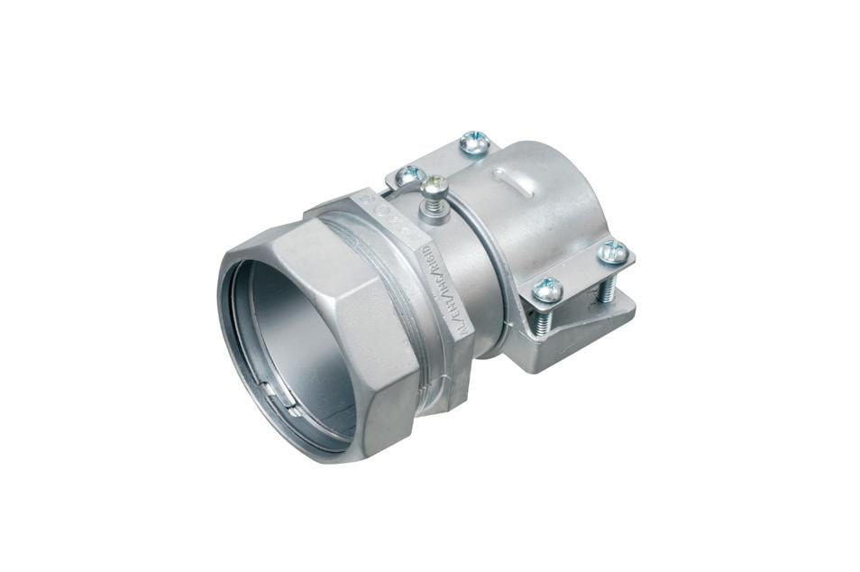
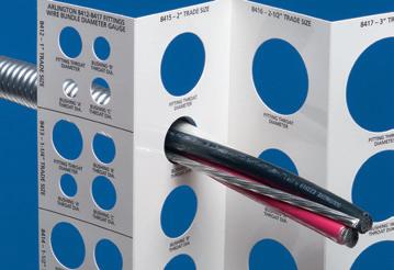
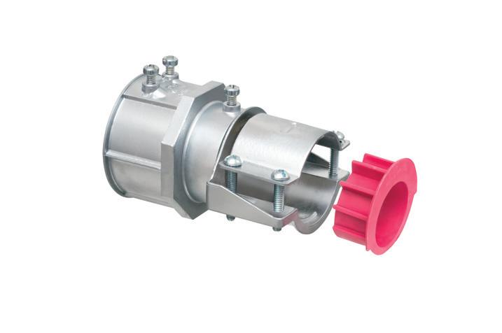
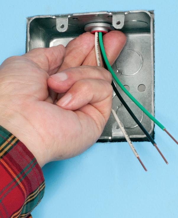
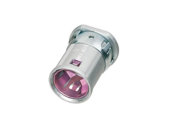
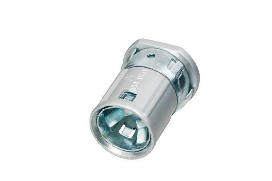
Perfect for data center remote power panel feeds, panels, equipment feeds and EV Chargers in parking garages, Arlington’s Listed CableStop® Transition Fittings deliver the efficient, cost-effective way to transition feeder cables to 1.25", 2.5", 3" and 3.5" EMT, IMC and RMC conduit in protective drops, risers and feeds to panels and equipment. Our new CableStop fittings integrate our patented, versatile and SKU-reducing 8412 series cable fittings, with Arlington conduit fittings, allowing for easy transitions to larger knockout sizes.
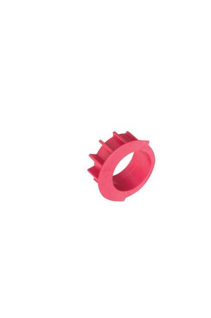
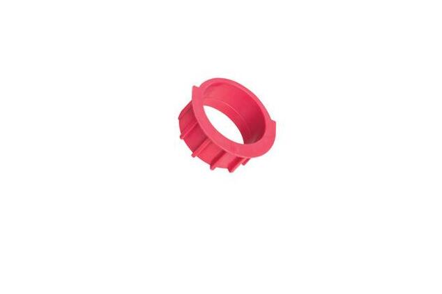
Available with set-screw or compression connections into 1.25", 2.5", 3" and 3.5" conduit, they ship with multiple end stop bushings that vary the size of the opening – along with a free template select the right bushing for the cable.
Reducing the Impact of Utility Switching Transients and Ferroresonance in Data Centers
Why modern data centers are uniquely vulnerable to power quality disturbances caused by utility switching operations and strategies to mitigate their impact
By Jayakrishna Kasturi, P.E., AWS
Data centers demand exceptionally high levels of power continuity and power quality. While most facilities are designed to ride through voltage sags and short interruptions, fast transient overvoltages and ferroresonant conditions remain an underappreciated failure mode. Utility switching operations such as capacitor bank energization,
transformer switching, feeder reconfiguration, or breaker reclosing can generate transient events that exceed the dielectric and control tolerances of sensitive power electronics. In parallel, lightly loaded transformers, long cable runs, and modern low-loss magnetic cores create ideal conditions for ferroresonance, particularly during abnormal switching scenarios. As data
centers scale in size and density and as utilities adopt more automatic switching schemes these risks are increasing rather than diminishing.
UNDERSTANDING UTILITY SWITCHING TRANSIENTS
Sources of switching transients Switching operation is the most common
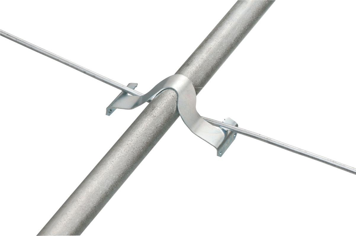
Arlington’s time-saving flexible spring steel are the answer to vertical or horizontal conduit to rod, wire or flange support.
Available in multiple sizes, they also support flexible metallic tubing, armored cable, portable cables, control tubes and communications cable.
• For EMT, rigid, ENT, IMC, aluminum conduit and metal-sheathed cables
• Easy NO TOOL installation
INSIDE PQ
Illumination Insider
This e-newsletter tracks the research, development, design, installation and operation of all types of lighting and control products. This monthly product is geared toward professionals working in the industrial, commercial, retail, residential, institutional, health care, government, and utility market sectors.
Subscribe Today
See all of our EC&M e-newsletters at www.ecmweb.com
cause of transients, in addition to other reasons like network faults and lightning strikes. Common utility-side operations that generate transients include switching capacitor banks, shunt reactors or harmonic filters, transformer energization and de-energization, vacuum circuit breaker restrikes, automatic reclosing following feeder faults, and switching of shunt reactors or harmonic filters. These events can generate steep-fronted voltage impulses with rise times in the microsecond range. While brief, they can stress insulation systems, trigger misoperation of protective relays, upset UPS controls and static transfer switches, and propagate through transformers due to capacitive coupling.
Why are data centers more susceptible?
Data centers differ from traditional industrial loads in several ways that make them more susceptible to these disturbances. Data centers are more susceptible to ferroresonance because they feature a high concentration of power electronic interfaces, including UPSs, rectifiers, and inverters, along with extensive use of long medium-voltage (MV) cable runs. Data centers typically have lightly loaded or no-load transformers during certain operating modes, and IT equipment maintains a tight tolerance to common-mode noise. As a result, even the transient events that comply with utility standards may still cause functional disturbances inside the facility.
FERRORESONANCE: A SILENT BUT SEVERE RISK
What is ferroresonance?
Ferroresonance is a nonlinear resonance phenomenon that occurs when transformer magnetizing inductance, system capacitance from cables, bushings, and breaker grading capacitors, and a switching event or single-phase condition combine under the right conditions. Unlike linear resonance, ferroresonance can produce sustained overvoltages ranging from two to four per unit, subharmonic or chaotic waveforms, overheating of transformers and voltage transformers, and catastrophic failure of auxiliary equipment.
Common data center triggers
In data centers, ferroresonance is most often associated with singlepole switching of MV breakers, energizing unloaded or lightly loaded transformers, isolated or ungrounded MV systems, long underground cable feeders, and open-delta or wyeungrounded VT configurations. These conditions are common during com missioning, maintenance switching, or abnormal utility operations.
Design-level mitigation strategies
Preventing ferroresonance requires addressing root causes during the design phase through proper equip ment selection, switching methods, and grounding practices. The following design considerations must be evalu ated during planning and specification of data center electrical systems to elimi nate ferroresonant conditions, improve system reliability, and protect equipment and personnel.
Controlled (point-on-wave) switching
One of the most effective mitigation measures is controlled switching, also known as point-on-wave switching. By closing breakers at the optimal point on the voltage waveform, controlled switching minimizes transformer inrush current, reduces transient over voltages, prevents breaker restrikes, and lowers the likelihood of ferroreso nant initiation. Controlled switching is especially beneficial for transformer energization, capacitor and reactor switching, and high-voltage utility interconnections.
Transformer and VT selection
Key transformer design considerations include avoiding lightly loaded operating conditions where possible, specifying core designs less prone to saturation, and using grounded-wye configurations where system design allows.
For voltage transformers, it is important to avoid open-delta VT configurations on MV systems without damping resistors, use grounded-wye VTs with appropriate burden, and consider ferroresonance damping resistors where required. It is recommended to
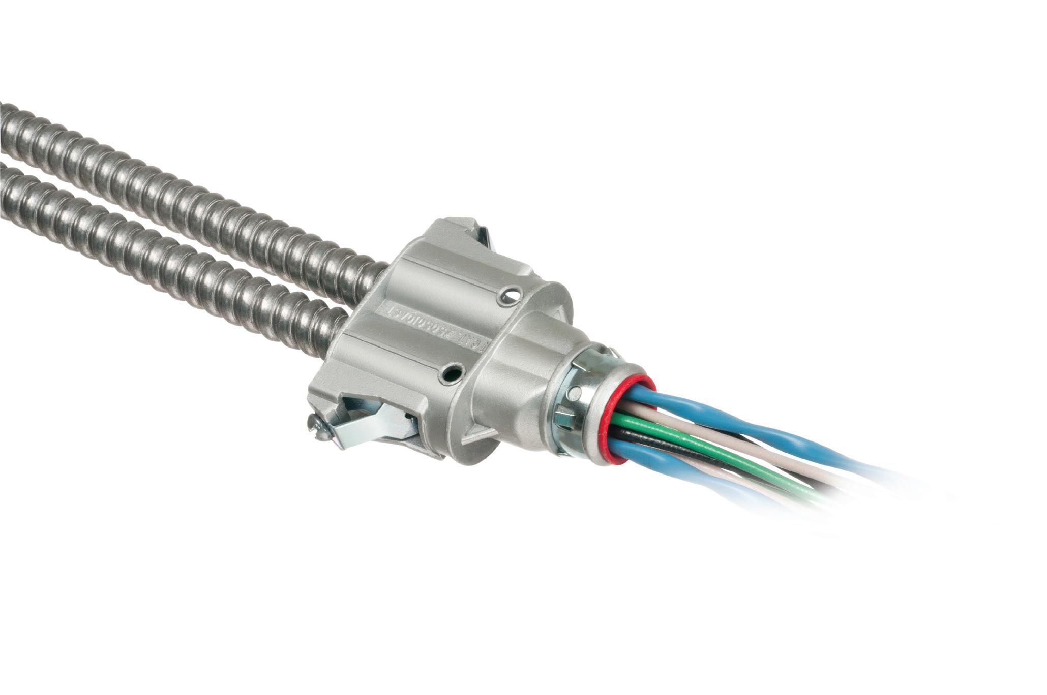
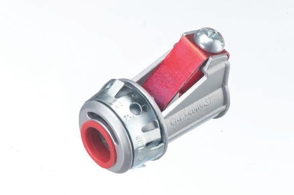
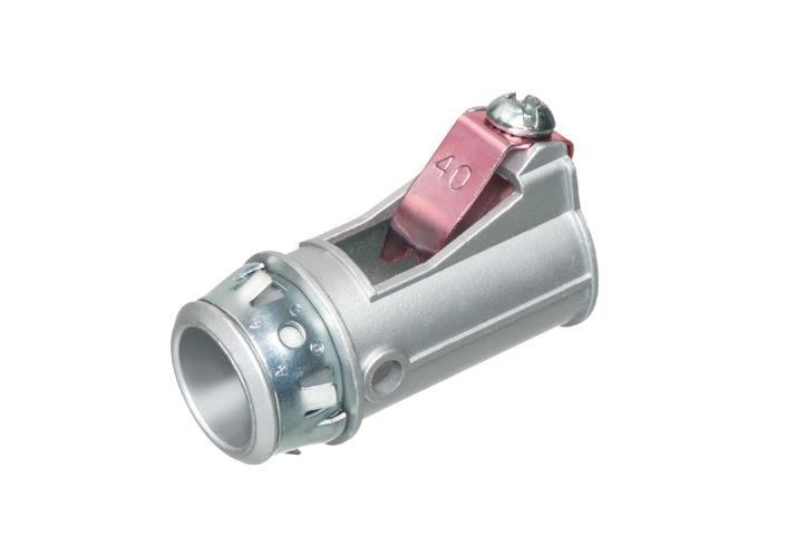
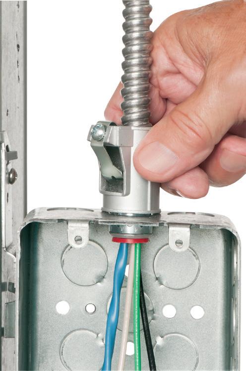
SNAP2IT® CONNECTORS
17SAVE seconds
Fully assembled, SNAP2IT® fittings handle the widest variety of MC cable AND THE NEW MC-PCS cables.
Compared to fittings with a locknut and screw, you can’t beat these snap in connectors for time-savings!
LISTED SNAP2IT ® CONNECTORS FOR NEW MC-PCS CABLE ...lighting & low voltage circuits in the same cable
• Fits widest range and variety of MC cable 14/2 to 3/3
AC, MC, HCF, MC continuous corrugated aluminum cable and MCI-A cables (steel and aluminum)...including the new MC-PCS cable that combines power and low voltage in the same MC cable
ANY Snap2It Connectors LISTED for MC cable are also LISTED for MC-PCS cable! These products offer the greatest time-savings.
• Fast, secure snap-on installation
• Easy to remove, reusable connector From cable Loosen screw on top. Remove connector from cable. From box Slip screwdriver under notch in Snap-Tite® Remove connector.
Easy to Snap into Box!
INSIDE PQ
Safety Matters
This twice-a-month e-newsletter delivers the latest trends and information on electrical safety, reports on specific accidents in the field, and provides tutorials and evergreen safety content that can be used for reference and training.
Topics covered include:
• Best practices for safely working on electrical equipment
• Accidents and investigations
• Arc flash
• PPE
• Shock and electrocution
• Fire and security
• Safety audits
Subscribe Today
See all of our EC&M e-newsletters at www.ecmweb.com
use VTs with higher over voltage factors while also considering dual secondary winding VTs with one of the windings connected in open-delta with a damping resistor. The damping resistor across the open-delta terminals is typically sized around 30% to 40% of the transformer’s magnetizing reactance.
Grounding practices
Grounding is a decisive factor in ferroresonance risk. Best practices include solidly grounding MV systems where permitted, avoiding floating or highimpedance grounded systems without thorough analysis, and ensuring consistent grounding reference across substations, UPS systems, and PDUs. A well-designed grounding system reduces both transient overvoltages and chaotic ferroresonant behavior.
MEDIUM-VOLTAGE AND FACILITY-LEVEL CONTROLS
Surge protection and transient suppression
Surge protection should be applied in layers, with station-class surge arresters at utility entrances, distribution-class arresters at MV switchgear, and secondary surge protection at UPS and PDU inputs. Proper arrester selection must consider maximum continuous operating voltage, temporary overvoltage capability, and energy absorption rating.
Switching philosophy and interlocks
Operational strategies are as important as hardware. Facilities should avoid single-pole switching where possible, sequence transformer energization under controlled load, use interlocks to prevent abnormal switching states, and coordinate utility and facility switching procedures.
UPS and power
electronics
considerations
UPS systems are often the first devices affected by switching transients. Mitigation measures include input isolation transformers, dv/dt filters and EMI suppression, active frontend rectifiers with robust control algorithms, and tight synchronization
between parallel UPS modules. UPS vendors should be required to demonstrate immunity to fast transients and common-mode disturbances.
MODELING, MONITORING, AND VALIDATION
Electromagnetic transient studies
Traditional power flow and short-circuit studies are insufficient for addressing these phenomena. Facilities should perform electromagnetic transient studies using tools such as PSCAD or EMTP, conduct ferroresonance sensitivity analysis, and run switching transient simulations for credible utility scenarios.
Power quality monitoring
Permanent power quality monitors should be installed at utility interconnection points, MV switchgear buses, and UPS inputs and outputs. Captured data allows operators to correlate IT events with power disturbances, validate mitigation effectiveness, and engage utilities with factual evidence.
CONCLUSION
Utility switching transients and ferroresonance are not theoretical concerns; they are real, documented causes of data center disturbances and equipment damage. As power systems become more automated and more inverterdominated, these risks will continue to grow. By combining thoughtful design, controlled switching, robust grounding, careful equipment selection, and advanced modeling, data center operators can significantly reduce exposure to these phenomena. In an industry where milliseconds matter, proactive mitigation of transient and ferroresonant events is no longer optional; it is a fundamental element of resilient data center power design.
Jayakrishna Kasturi, P.E., is a professional electrical engineer with extensive experience in low-, medium-, and high-voltage power systems and power system analysis. His work includes substation design, power quality studies, and resilience planning for large-scale mission-critical facilities.
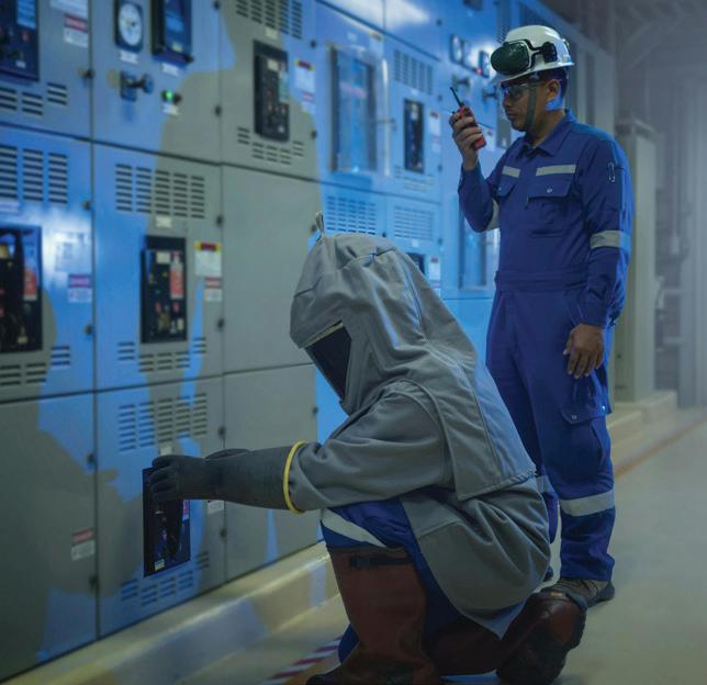
How modern monitoring and AI are changing electrical safety and why most facilities are sitting on untapped insight
By Joseph Deane, PE, Shermco
In the course of reviewing microprocessor-based relay and metering data across several hospital and industrial facilities, I kept running into the same situation: the data was there. Voltage disturbances, harmonic trends, power quality anomalies, all of it logged, timestamped, sitting in the device. And, in most cases, nobody had looked at it — not recently, and not ever.
That’s worth sitting with for a moment. These are hospitals. Facilities where power quality directly affects patient care equipment, surgical suites, and life-safety systems. The monitoring infrastructure was doing its job. The gap wasn’t technology; it was process. So if the data is already there, the real question is: Is anyone looking at it? This is the central problem predictive maintenance is designed to solve — not the absence of data, but the failure to act on it.
HOW ELECTRICAL FAILURES ACTUALLY DEVELOP
Most electrical failures don’t begin with a fault. They begin with a trend. Insulation that degrades gradually. A connection that loosens over months of thermal cycling. Harmonic distortion that builds slowly as nonlinear loads are added to a system. These conditions rarely trip a breaker or trigger an alarm. They accumulate quietly until something gives.
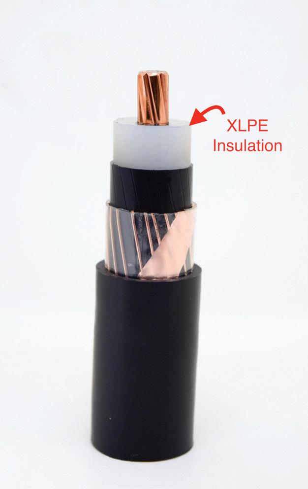
At one major health care facility, a power cable installed in violation of the manufacturer’s instructions began degrading slowly. The eventual arc flash event was significant enough to cause serious equipment damage and a lengthy outage. It
occurred late at night, which fortunately prevented personnel injuries. Had the trending data been reviewed routinely, the gradual insulation degradation may have been visible well before the failure point.
An arc flash event or equipment failure is often the final link in a chain. The earlier links were there. In many cases, they were being recorded. The opportunity predictive maintenance offers is to identify those earlier links before the chain runs out.
NFPA 70B: A STANDARD THAT REFLECTS THIS REALITY
The transition of NFPA 70B from a recommended practice to a standard is a meaningful shift. For decades, electrical
maintenance programs were largely time-based: inspect on a schedule, test at fixed intervals, regardless of what the equipment was actually doing between visits. That approach worked reasonably well, right up until it didn’t.
NFPA 70B reinforces condition-based thinking. It asks a direct question of facility owners and engineers: If your equipment can tell you about its health in real time, are you using that information? For most facilities today, the honest answer is not fully.
WHAT’S ALREADY IN THE BUILDING
The foundation for predictive maintenance is already installed in most facilities. The challenge is using it.
Microprocessor-based protective relays
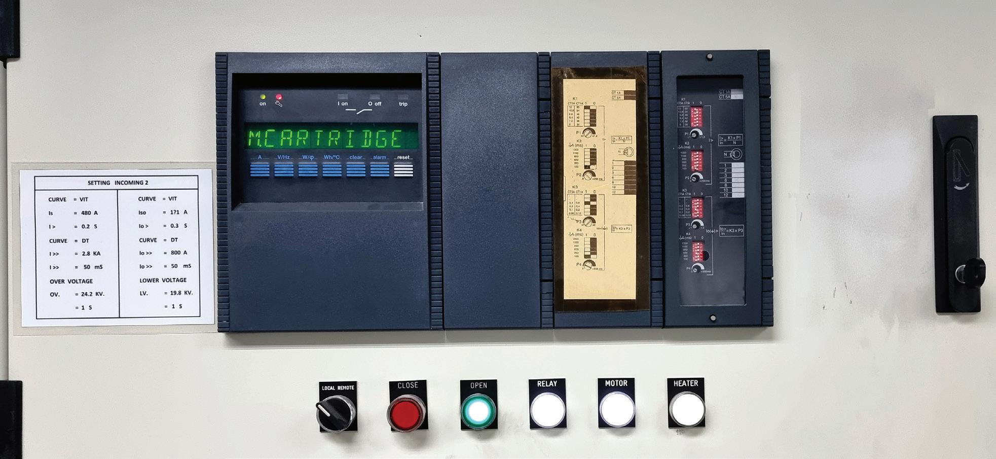
Modern relays are far more than trip devices. They continuously capture fault currents, voltage, and current waveforms, breaker operation timing, and event records (Photo 1 on page 46). Traditionally, this data is pulled only after something goes wrong. Reviewed as a trend over time, it tells a different story; it shows where the system is heading rather than simply where it has been.
In one case, a customer’s microprocessor-based relay was configured with an alarm threshold for off-normal frequency while the site’s cogeneration unit was running. That alarm flagged an emerging generator loading issue before it developed into a problem, exactly the kind of early warning that
Pinyo
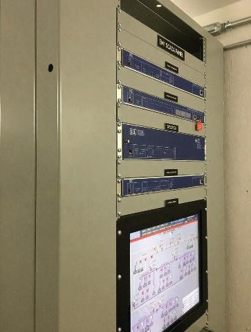
relay trend data is designed to provide, but only delivered because the alarm was tied to a mini SCADA system.
Power quality meters
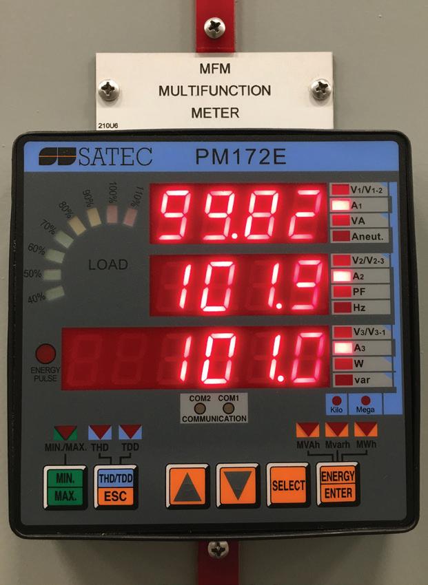
Power quality meters track harmonic distortion, voltage imbalance, transient events, and long-term behavioral trends (Photo 2). The key insight here is that power quality problems are often invisible from a protection standpoint; they don’t trip breakers. Instead, elevated harmonic content quietly increases heating in transformers, conductors, and motors, accelerating insulation aging over months and years. By the time a failure occurs, the contributing conditions are long gone from anyone’s memory. Even standard power quality meters, while not full Class A analyzers, provide enough harmonic and trend data to identify developing issues when reviewed over time.
At one facility, power quality metering identified a 480V dry-type transformer serving VFD-driven HVAC equipment with 35% total harmonic distortion, contributing meaningful non-60 Hz current through the transformer windings. This excess current produces heat, and that heat accelerates insulation aging. Nothing tripped. No alarm sounded. The transformer was simply running hotter than it should have been, every day, until we noticed while collecting data for an arc flash study.
Continuous thermal monitoring
Periodic infrared inspections are valuable but limited to the conditions that exist at the moment of the scan. Permanently installed thermal sensors within switchgear, bus structures, and cable terminations provide ongoing visibility. They catch gradual temperature increases that an annual walkthrough would never see.
At one facility, as part of the thermal monitoring program, IR window inspections of an energized switchgear lineup revealed a cable lug with a gradually rising temperature trend over successive inspection intervals. The lug was loosening. This condition would have been invisible to a single-point annual scan. Because readings were being tracked over time, the deterioration was caught before it became a fault, and the connection was remade under planned, controlled conditions.
WHERE AI ACTUALLY FITS
With relays, meters, and thermal sensors all generating data, the challenge shifts from collection to interpretation. A trained engineer reviewing relay records manually can identify trends across dozens of devices and months of data. However, that isn’t practical at scale. This is where AI provides genuine value.
AI systems can correlate data across multiple devices simultaneously. For example, identifying a gradual increase in 5th harmonic distortion following
Power quality monitoring can identify developing harmonic distortion and voltage quality issues before failures occur.
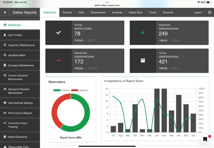
the addition of VFD-driven HVAC equipment, while also recognizing a corresponding rise in transformer temperatures in the same area. Neither condition alone may trigger an alarm, but together they indicate a developing issue. Platforms such as modern EPMS systems, combined with emerging AI-based analytics tools, are increasingly capable of performing this type of cross-system correlation (Photo 3). In practice, this is being implemented
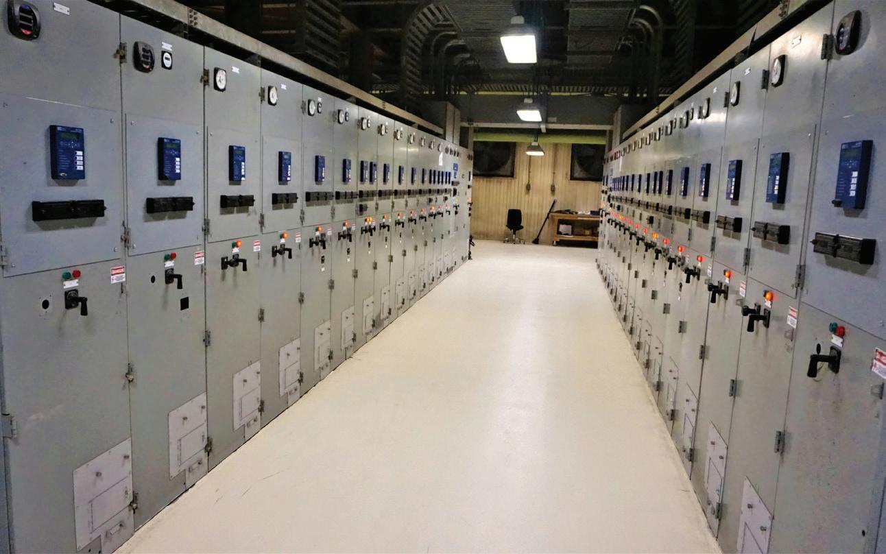
Photo 1. Microprocessor-based relay systems provide operational and event data that can support predictive maintenance programs.
Photo 2.
through platforms that aggregate data from relays, meters, and sensors into centralized systems where machine learning models can identify patterns across time and across equipment.
AI is not replacing engineering judgment here. It is doing the work that makes engineering judgment possible: surfacing the signal from the noise so that a qualified engineer can evaluate it and decide what action is warranted.
THE SAFETY IMPLICATIONS ARE DIRECT
From a safety standpoint, the value of predictive maintenance is straightforward: It converts emergency situations into planned ones. When a developing fault is identified early, maintenance can be scheduled under controlled conditions, with proper PPE, appropriate arc flash work permits, and adequate staffing. Compare that to an emergency response following an unexpected failure, where conditions are uncontrolled, and personnel exposure is highest.
This is the practical safety argument for condition-based maintenance; not just improved reliability, but reduced exposure to energized equipment in unplanned circumstances.
WHAT THIS ACTUALLY REQUIRES
Predictive maintenance is not a technology deployment. It is a program. The technology is only as useful as the process around it. A few things that matter in practice:
• Data quality matters. Sensors that aren’t calibrated, relays with incorrect CT ratios, or meters with communication gaps produce misleading trends. Garbage in, garbage out applies here as much as anywhere.
• Not every anomaly is actionable. AI systems will flag conditions that require human evaluation to determine significance. Engineering judgment is still the final step, not an optional one.
• Integration is often the hardest part. Data that lives in isolated devices, different software platforms, or systems that were never designed to talk to each other requires deliberate integration work before analytics are possible. Predictive tools complement established maintenance practices; they don’t replace them.
Relay testing, insulation resistance measurements, and infrared inspections still have a place in a complete program.
START WITH WHAT YOU ALREADY HAVE
The hospitals I mentioned at the start of this piece aren’t unusual. Across industrial and commercial facilities, there is a significant gap between the data that monitoring systems are collecting and the data that maintenance programs are actually using. Closing that gap doesn’t necessarily require new hardware. It requires a decision to start looking at what’s already there.
Modern relays, power quality meters, and thermal monitoring systems are
capable of supporting a genuinely predictive maintenance approach. AI makes that practical at scale. NFPA 70B is now reinforcing the expectation that facilities take this seriously.
The tools are in place. The data is being recorded. The question for facility owners and engineers is a simple one: Is anyone looking at it?
Joseph Deane, a registered Professional Engineer in multiple states, is Vice President of Engineering Solutions for Shermco Industries and former owner of KTR Associates, a consulting firm specializing in power system design and electrical safety. He can be reached at Joseph.Deane@Shermco.com.
Photo 3. Modern monitoring platforms aggregate relay, metering, and thermal data to support condition-based maintenance.
FLOOR BOX
Arlington’s CONCRETE FLOOR BOX and RECESSED COVER KITS
offer cost-savings and easy, flush installation of a receptacle and low voltage ports in a new concrete floor.
Our heavy-duty FLBC5500 non-metallic 5.5” concrete floor box has six conduit hubs, four plugs and MULTIPLE slots for positioning two low voltage dividers in the box.
Designed to fit the FLBC5500 box, FLBC5570 recessed cover kits come with two installed UL Listed 20A decorator-style receptacles, an ultra-thin stamped steel flange and two flush-to-the-floor covers. Also a low voltage divider and a 4-port keystone device.
Zinc cover, steel flange in 6 Finishes/Colors: PLATED in brass, nickel, antique bronze, POWDER-COATED in brown, black and light almond.
How the 2026 NEC is Changing Worker Safety
Clarified rules and new requirements help electrical contractors, designers, and maintenance teams reduce risk in real-world conditions.
By Randy Barnett, Electrical Code and Safety Specialist
There is little doubt that the National Electrical Code (NEC) is all about safety.
The Code’s stated purpose in Art. 90, “…the practical safeguarding of persons and property from hazards arising from the use of electricity,” makes it clear that our installation work must prevent shock and fire. The NEC also has installation provisions that more directly address the safety needs of those who operate, service, and maintain equipment (Photo 1). Of great importance is the protection of first responders who often encounter electrical systems but are not qualified electrical workers.
The 2026 NEC continues to revise its electrical safety installation rules to protect everyone — from the general public in their homes to the worker in the plant electrical room to the fire personnel responding to emergencies. This article highlights some key 2026 NEC changes that directly improve safety for workers.
MANUFACTURERS’ INSTRUCTIONS
“Follow manufacturers’ instructions” has long been heard when discussing Code enforcement. But what if those manufacturers’ instructions conflict with the NEC and result in an installation that does not meet the safety requirements of the Code? If you follow the Code but then violate Sec. 110.3(B) [Installation and Use], which requires following the manufacturer’s instructions, where does
that leave you? Revised wording now explains that manufacturer instructions are to be followed — as long as they do not conflict with NEC rules.
Examples of such conflicts can easily be found. For example, see Fig. 1 on page 52 for swimming pool heat pump installation instructions. The only protection requirements specified for the branch circuit is the heat pump be connected to a “suitable circuit breaker.”
Sec. 680.5 [Ground-Fault CircuitInterrupter (GFCI) and Special Purpose Ground-Fault Circuit-Interrupter (SPGFCI) Protection] requires Class A GFCI protection for pool accessory equipment. An SPGFCI may be
required for certain applications. The public, pool technicians, and service personnel must be protected from electric shock. Electricians must install the required GFCI protection even if not specified by the manufacturer.
ARC FLASH WARNING LABELS
Sec. 110.16 [Arc Flash Hazard Marking] is a good example of a Code requirement specifically designed to protect electrical workers. When it comes to following safety procedures, workers want simplicity and conciseness: “Just tell me what I need to wear and what I need to do to protect myself — don’t complicate it for me.” Previous Code language tended to complicate
METER MOUNTING BASE
Remove flanges for retrofit work
Arlington’s one-piece, non-metallic Mounting Bases provide a smooth, flat mounting surface for most electric meters, including the largest sizes – as well as a variety of other products such as timers, disconnects, inlet boxes and more.
UV rated, paintable plastic for long outdoor life.
Squared-off corners make them gangable so you can create the mounting base needed for the product you’re installing.
recessed STEEL combination power/low voltage TV BOX® is the best way to mount an LED or Hi-Def TV flush against a wall.
TV BOX provides power and/or low voltage in one or more of the openings. Plugs and connectors stay inside the box, without extending past the wall.
Designed for use in new or retrofit commercial construction where metal raceway is used, we have a STEEL TV BOX for almost any application!
• Steel box; non-metallic paintable white trim plate
• Easy, secure installation
• Optional covers
Gangable...for custom sizing
arc flash information needed by the worker. It was wordy and referenced other documents rather than just stating the rules. Clarifying these requirements now helps implement safe work practices. When the worker approaches the equipment, the arc flash warning label must be clearly visible (Photo 2). Information on the label is now required to provide nominal voltage levels used to establish approach boundaries and select the appropriate level of voltage-rated rubber goods. And the required arc flash protection information will allow the trained person to select the correct arc-rated PPE. The Code now provides the worker with the safety information to proceed.
WORKING SPACE
Section 110.26 [Spaces About Electrical Equipment] emphasizes a working space requirement to ensure workers can egress the work area in the event of an incident, such as a fire or arc flash. A minimum width of 24 inches has been in previous Code editions, as this width is adequate for egress in an emergency. However, consider an injured worker attempting to find their way out of a dark and smoke-filled electrical room. If 24 inches is needed, what happens to the worker if panel doors on either side of the egress route just happened to be open at 90 degrees, and that 24 inches was drastically reduced? The worker may struggle to exit the area. The wording in Sec. 110.26 was changed to clearly reflect that access or egress is impeded if the space is reduced to be less than 24 inches wide and 61/2 feet high when doors are (or can be) opened 90 degrees. Photo 3 on page 54 illustrates a potential situation.
Electrical contractors and designers will have to consider the effect this rule may have on future installations in smaller work areas with larger equipment. Yet an injured person in shock, in a dark room filled with smoke, must still be able to quickly exit that area, and responders must be afforded adequate access.
BARRIERS FOR SAFETY
The revision to the title of Sec. 230.62 [Service Equipment — Enclosed or Guarded, and Barrier Placement] now emphasizes the need for the use of identified barriers for both shock and arc flash protection for workers by adding the words “and Barrier Placement.” The requirement now specifies that these barriers are to be placed so that “energized” terminals and bus work of service equipment cannot be inadvertently contacted. Thus, the barriers must be placed on the line-side terminals of the service equipment.
Fig. 1. NEC Sec. 110.3(B) now makes it clear that installations, even when following manufacturers’ instructions, must still comply with the Code. These electrical installation instructions for a pool heater do not include GFCI protection, are obviously generic in nature, and could create confusion for installations if they were to be followed.
2. As per Sec. 110.16 of the NEC, arc flash warning labels must be clearly visible to qualified workers. This Code require ment also dictates what must be on the arc flash warning la bels, thus clarifying the shock and arc flash protection provisions they need to implement.
Such barriers are placed for more than just electric shock protection. Exposed live terminals also present a potential arc flash hazard should an uninsulated tool or conductor acciden tally contact or come into contact with the terminals. This may occur during testing long after installation ( 54). Service conductors supplying a service are typically not protected by overcurrent protection on the secondary side of the serving utility transformer, and workers can be exposed to abnormally large arc flash events. Specifying the location of these identified barriers on energized terminals and bus work service equipment only increases worker safety.
DISCONNECTS FOR WORKER SAFETY
Numerous requirements for disconnect means appear throughout the Code. Disconnect switches serve an important function by allowing lockout/tagout of equipment. Location and labeling help workers and first responders quickly and safely remove power from energized equipment during an emergency.
For service equipment, Sec. 230.70 [General] has relocated rules for disconnect locations to make it clear that one- and two-family dwelling unit service disconnects must be readily accessible outside the building. In other than one- and twofamily dwellings, service disconnects must be located readily accessible either outside the building or inside nearest the point of entrance of the service conductors. Service disconnects on other than one- and two-family dwellings must now be labeled “SERVICE DISCONNECT.” This new label requirement removes confusion, especially for the first responders. Terms such as “Mains” or “Main Disconnect” do not match the terminology in the Code for this equipment. Improper labeling could also create confusion with multiple disconnects in one location.
Photo
Arlington’s Low Voltage Mounting Brackets are the solution for fast and easy cut-in installation and mounting of Class 2 communications, computer and cable TV wiring and connections.
Introducing METAL low voltage mounting brackets for EXISTING or RETROFIT construction...
LV1M and LV2M COMMERCIAL GRADE
• Extra rigidity and stability where performance and visibility are important or critical
• Threaded holes for easy, fast device installation
• Adjustable bracket for 1/4" to 1" wall board thicknesses
Our LV1S and LV2S PLATED STEEL bracket design, provide excellent stability and secure installation of low voltage devices in 1/4" to 1-1/4" walls - without an electrical box.
Photo 3. NEC Sec. 110.26 requires a 24-inch width of working space for safe egress for workers in the event of an emergency, even if the doors on both sides of the corridor are open 90 degrees. This is probably not an issue in this image, but in a smaller electrical room, this 24-inch requirement could become a consideration for worker safety.
For one- and two-family dwellings, service disconnect enclosures must be marked “EMERGENCY DISCONNECT” with the marking on the outside front of the disconnect enclosure using white letters at least one-half inch high on a red background, as shown in Photo 5.
Fire personnel responding to an electric vehicle fire must safely shut off the power. Section 625.43 [Disconnecting Means] now requires an emergency shutoff for all Electric Vehicle Supply Equipment (EVSE) and Wireless Power Transfer Equipment (WPTE) in other than one- and two-family dwellings (Photo 6 on page 56). The disconnect must be located between 20 feet and 25 feet from the charging equipment, thus keeping the shutoff reasonably close to the EVSE or WPTE, yet providing ample distance from the equipment to allow first responders to approach the fire from a safe distance to shut off power (Photo 5).
DAMAGED WIRING
A new Sec. 300.4(C) requires damaged wiring to be replaced. The new provision not only gives AHJs enforcement direction, but these requirements also provide worker protection. One might think using the word “repaired” would be more practical in some instances. However, it is often difficult to determine damage to insulation that cannot be seen.
Exposing conductor insulation rated only for dry and damp locations to water damage is an obvious issue. Insulation absorbs moisture, and insulation resistance testing can often be used to determine the presence of moisture. However, medium-voltage (MV) cable has a more complex insulation system than insulation rated for 600V. This XLPE and EPR MV insulation deterioration and failure can cause catastrophic failure long after exposure to water. Even though insulation test values may indicate satisfactory values, the damage is already done (Photo 6 on page 56).
Replacement of water-damaged wiring is the best alternative for protecting operations and maintenance personnel who will be operating and maintaining systems. In fact, the CodeMaking Panel noted that no such code rule existed to protect the worker from this hazard, and this new requirement “enhances electrical safety and helps satisfy the practical safeguarding as required by the code purpose.” Fortunately, two Informational Notes are included, providing NEMA references to evaluate equipment and wiring for fire, heat, and water damage.
IN SUMMARY
The NEC is responsible for protecting all persons, not just the general public
Photo 4. Section 230.62 of the NEC outlines the requirement for identified barriers on service equipment. Identified products ensure the barrier helps protect workers from electric shock due to inadvertent contact. The small hole in the barrier protects testing and maintenance personnel by providing safe access for test leads to energized terminals.
Photo 5. NEC Sec. 230.70 requires service disconnects to be located outdoors and readily accessible. For one- and twofamily dwellings, the disconnect must be marked “EMERGENCY DISCONNECT” with minimum half-inch white letters on a red background. Other than one- and two-family dwellings must be marked “SERVICE DISCONNECT.” There is no prohibition against marking this one-family dwelling “SERVICE DISCONNECT” as long as the marking “EMERGENCY DISCONNECT” appears.
Plastic & Steel 8X10 TV BOX®
Arlington’s 8X10 TV Box® with a Plastic or Steel Box offers the ultimate in versatility for installing TVs in new and retrofit projects. There's more room in the box for wires and it installs horizontally or vertically to properly position low voltage connections behind the TV.
• Ideal for home theater systems: multiple connections for sound systems, satellite TV, CATV, DVRs
• Brackets for neater cables, with a 1-1/2" knockout for ENT and other low voltage wiring
• Box mounts to stud in new work; for retrofit, mounting wing screws secure
fittings are easy to use in an OLD WORK installation, and handle the widest variety of cables! They’re ideal for adding additional circuits to a load center. And you get the same labor-savings in a retrofit installation!
Easy snap-in installation - NO TOOLS. Install connector into the knockout in an existing box, pulling cable/conduit through the knockout. Slip the fitting onto the cable, then snap the assembly into the box. That’s it... a secure installation with no pullout
Widest total cable ranges 14/2 to 10/3 Widest variety of cables AC, MC, HCF, MC continuous corrugated aluminum cable, MCI-A cables (steel and aluminum), AC90,
Photo 6. Several new and revised provisions in Sec. 625.43 help protect maintenance personnel and first responders. Proper placement, marking, and type requirements of the EVSE or WPTE emergency shutoff allow operation of the shutoff at a safe distance from the charging station in the event of an incident, yet the emergency shutoff means is close enough for ready access.
Code Rules Change to Reflect Safety and Practicality
NEC rules today are promulgated based on studies, engineering data, and public input, with the idea of preventing incidents before they happen — proactive rules rather than reactive ones. Here are two examples for us to review.
Service disconnects. Fire and life safety were the considerations of the first electrical code published in 1897 by the National Board of Fire Underwriters. It stated, “Switches must be placed on all service wires, either overhead or underground, in a readily accessible place as near as possible to the point where the wires enter the building…”. By 1925, two service disconnects were permitted, since a disconnect may be required for the store on the ground floor and another for the residence located above the store. By the 1933 edition of the NEC, the six-disconnect rule had come into place based on needs. The 2020 NEC required that “up to six disconnects be in separate enclosures” for safe operation.
Temporary wiring and Installations first appeared in the 1971 NEC. Article 590 [Temporary Installations] requires guards over temporary lamps to protect them from accidental breakage and worker shock incidents. The 2026 NEC recognizes that changes in technology have produced safer lighting alternatives. Section 590.4(F) now allows listed temporary lighting strings with non-replaceable LED lamps to not require a guard. Rules are relaxed, but safety is maintained.
Photo 7. Section 300.4(C) now requires damaged wiring to be replaced. Insulation, such as this medium-voltage XLPE cable, is especially prone to water damage, which can result in premature failure. A surprise no worker should face in a switchgear when performing routine maintenance tasks.
who occupy buildings and dwelling units. In many cases, Code rules are provided specifically for those who must operate and maintain electrical systems and equipment. In most cases, these persons will not be qualified electrical workers (plant operators, mechanics, pipefitters, welders, service technicians, and so on). In the event of an emergency, it is extremely important to provide first responders with correctly marked and accessible means to disconnect power from a safe location and then respond to the emergency. The 2026 NEC did make some specific revisions to enhance worker safety — thank you to the Code-Making Panels.
Randy Barnett is a master electrician, ICC Commercial Electrical Inspector, NFPA-certified Electrical Safety Compliance Professional and has worked as an electrician and technician in nuclear and coal-fired power plants, government nuclear research facilities, and in industrial maintenance and construction. He can be reached at electricrb@yahoo.com.
PODCASTS
Listen on Your Favorite Podcasting App
EC&M ON AIR
Presenting new electrical insights, market data, technical information, and helpful hints in 30 minutes or less
Editor-in-Chief Ellen Parson hosts two to four episodes of “On Air” per month, discussing hot topics with industry subject matter experts and business leaders, delivering industry trends, best practices, and current events to our audience. ecmweb.podbean.com
CODE CONVERSATIONS
Interpreting the NEC with Code Consultant Russ LeBlanc in 10 minutes or less
EC&M Code Conversations is a podcast series presented by NEC Consultant Russ LeBlanc and Editor-in-Chief Ellen Parson. In 10 minutes or less, Russ and Ellen sit down twice a month to discuss difficult-to-decipher requirements in the National Electrical Code (NEC) and how to apply those Code rules in real-world settings. ecmwebcodeconversations.podbean.com
By Tim Kridel, Freelance Writer
Strategies for Maximizing
Complacency and poor communication are the top concerns in workplace safety. Four experts explain why — and offer tips to protect employees, trades, and clients.
Meetings at the start of every shift help boost safety by covering change orders, trades on site, and other day-to-day variables that can create new hazards and affect requirements such as safe access to temporary power.
Experience is a great way to avoid unnecessary risks. It’s also a great way to take unnecessary risks because if you can do something in your sleep, you might be sleepwalking into danger. In fact, when EC&M asked safety and risk management experts to list the top reasons for workplace incidents, the same word kept coming up.
“Complacency is probably the biggest driver for risk in any job,” says Kevin Kolhonen, JM Electrical Company
health and safety manager. “With the mundane day-to-day tasks, people tend to get into routines.”
“Complacency and assumptions are surefire ways to increase risk,” says D. Scott Risch, Rosendin Electric senior vice president of health, safety, and environmental.
“Complacency stemming from routine work, often reinforced by repeated success despite unsafe behaviors,” says Travis Keeney, Tri-City Electric vice president of risk management.
As counterintuitive as it might sound, they also agree that certain other types of routines can mitigate risk.
“The biggest thing is breaking that and getting people thinking: speaking with crews, meeting with foremen onsite, and driving home pre-task plans,” Kolhonen says. “Every day before you start work, eliminate the hazards that you’re going to be diving into throughout the job.”
Rosendin Electric’s pre-task work plan is a two-day process.
“Our foremen begin preparing and planning the day before to ensure everything has been considered before crews arrive, ready to work,” Risch says. “After reviewing the plan and discussing, our crews inspect their tools and equipment and verify that their work area is free from hazards. Neglecting lockout/ tagout (LOTO), working on live equipment, ignoring clearances, or using damaged tools and cords are all hazards that can and should be identified before the work begins.”
A team effort is key.
“We treat mental health as seriously as physical health,” Risch says. “Checking in with team members is an important part of preparing for the day ahead. Sometimes our colleagues have an off day and aren’t as focused as usual. We follow two-person verification for all high-risk activities.”
Daily pre-task planning is also an ideal opportunity to consider how change-orders affect safety requirements.
“Formal stop points are implemented whenever the scope of work changes,” Keeney says. “At these points, crews regroup to reassess conditions,
JM Electrical Company, Inc.
identify any new hazards, and develop appropriate mitigation strategies before proceeding with the revised task.”
EVERY DETAIL COUNTS
Another common recommendation is that details matter. For example, don’t leave LOTO tags blank.
“Make sure you actually fill out the tag so somebody can contact you,” Kolhonen says. “A lot of people miss that step even though it’s so simple.”
Labels for arc flash and shock are another important detail.
“NFPA 70B, the standard on electrical equipment maintenance, and NFPA 70E, the standard on electrical safety in the workplace, don’t differentiate between the maintenance required for temporary power systems as opposed to permanent power systems,” says Lanny Floyd, who’s spent nearly a half-century as a workplace and occupational electrical safety expert. “I often see temporary power systems strung up on substandard construction sites. They have not been maintained for a while. Arc flash and electric shock warning labels should have a date on them, and that date should not be older than five years. That’s something to look for as you walk around a facility.”
Completing LOTO tags also highlights how electrical can help other trades work safely.
“About half of the electrocutions in the U.S. occur in construction,” Floyd says. “According to OSHA and BLS data and reports from the Electrical Safety Foundation International, about half of the electrocution fatalities each year are not electricians — they’re everybody else. They’re the painters, truck drivers, carpenters, scaffold erectors. About half of the fatalities each year are due to contact with overhead power lines.”
Pre-task planning is an ideal time to identify those kinds of risks.
“When walking around the facilities, where do you have exposure?” Floyd says. “Where there’s vehicular traffic underneath area lines, and how is that exposure controlled? Those routes need to be identified and controls established to prevent vehicle and personnel contact”
Getting input from the general contractor and other trades helps identify those risks, such as where boom trucks will drive and park to load drywall up
Low-voltage systems still can be hazardous if nearby higher power inadvertently energizes sprinkler pipes and other infrastructure. Daily pre-shift meetings are an opportunity to remind electricians to keep an eye out for those hazards.
to the third story. Those interactions are also opportunities to understand each trade’s power requirements so they don’t rig up their own to keep on schedule.
“The first step is to meet with the general contractor to fully understand their temporary power needs,” says Rosendin’s Risch. “Next, install sufficient receptacles for cordless tool battery charging stations for projects that are going cordless, designated areas for charging mobile elevated work platforms, and receptacle banks in sufficient quantity to prevent the excessive need for daisychained extension cords.”
GFCIs are another must-have safeguard.
“The GFCI is probably the single most important advancement in electrical safety technology in the last 100 years,” Floyd says. “We need to go beyond compliance. Don’t just make sure they’re where the Code says they need to be. Make sure that there are GFCI-protected circuits in all locations where a person could be holding a cordpowered tool or extension cord and be in a conductive grounded environment, such as standing on concrete, metal grating, or earth.”
PPE FOR POE
Installing surveillance cameras, alarms, and Wi-Fi access points involves
working with low voltages and near high voltages. One obvious reason is that 120V is often in the same enclosure as the low-voltage wiring. Other reasons are less obvious, which is why they can be debilitating or deadly.
“We had a guy working up in a ceiling, and there was an open box in the ceiling that was making contact with the sprinkler pipe,” says JM Electrical’s Kolhonen. “So that whole pipe became energized without him knowing. He made contact and got hurt pretty bad. He was up on a ladder, and a guy had to kick the ladder out from beneath him because he was locked up on the live voltage. People overlook the dangers of working up in the ceiling.”
A Tri-City electrician had a near miss while working on low voltage above a drop ceiling. Another firm had the electrical contract and left some fixture whips hanging down. That circuit was supposed to be off, but it wasn’t. Those are among the hazard scenarios that make the case for smart PPE, the topic of a May 2025 EC&M feature, “Tracking Wearable Safety Tech Trends.”
“As an added safeguard, Tri-City leverages technology, such as wearable voltage detectors, as a final line of defense against human error,” says Keeney.
Some wearables are wristwatch style. As the hand approaches an energized
JM Electrical Company, Inc.
THE SAFER WAY TO BETTER PROJECTS
By Kayla Fonseca, Faith Technologies Incorporated (FTI)
Why safety culture is a competitive advantage for electrical contractors
Electrical construction has always involved risk. Crews regularly work around energized systems and in environments where job-site conditions can change quickly. While those realities have not changed, the way electrical contractors approach safety has shifted significantly over the past decade.
Not long ago, safety was often viewed primarily as a compliance requirement or something managed mainly by the safety department. Today, many contractors recognize that safety is closely connected to how well projects are planned and executed. In my experience, the companies that treat safety as a core value tend to plan their work more carefully and deliver more predictable project outcomes. As electrical systems become more complex and project timelines continue to accelerate, safety culture is emerging as a meaningful differentiator across the industry.
MOVING BEYOND COMPLIANCE
One of the most noticeable shifts in the construction industry has been how the responsibility for safety is shared across project teams. Dedicated safety professionals
WHERE FACILITY CHALLENGES FIND SOLUTIONS
NORTHERN CALIFORNIA
NORTH TEXAS
August 19-20, 2026
Reno, NV
October 6-7, 2026
Santa Clara, CA
October 14-15, 2026
Irving, TX
remain essential, but strong safety programs work best when everyone involved in the work takes ownership.
At Faith Technologies Incorporated (FTI), safety is integrated into the way projects are planned and executed from the beginning. Project managers, foremen, and electricians, for example, are expected to evaluate hazards as part of the planning process so safety becomes part of the production conversation from the very start of the project, rather than something addressed after work begins.
Approaching work this way changes how safety is experienced in the field. Instead of reacting to rules or inspections, crews think through tasks before they start and identify the safest ways to perform the work. The goal is straightforward: making sure everyone goes home safe at the end of the day.
Leadership engagement plays a critical role in making that shift possible. When supervisors and field leaders actively participate in safety planning and discussions, expectations become embedded in the way teams operate. Safety is no longer something introduced by a safety professional; it becomes part of how crews approach their work every day.
SAFETY AND PROJECT RELIABILITY
Project owners today expect electrical contractors to deliver projects quickly and correctly the first time. Schedules are tight, and electrical systems are becoming increasingly complex, which means disruptions can have significant consequences.
In many cases, safety performance reflects whether a contractor has the discipline needed to manage those challenges. A clean, organized job site is often a sign that the project has been properly planned and coordinated. Material is staged where crews need it, and teams have a clear understanding of what comes next. When crews understand their tasks and the hazards involved, jobs tend to move more efficiently and with fewer unexpected issues.
Many project owners have begun to recognize that connection. Contractors who manage safety well often demonstrate the same level of discipline in other areas of project delivery. The planning
and communication that support safe work also support reliable schedules and consistent quality.
There can be financial implications as well. Contractors with strong safety performance often see advantages on the insurance side, which can translate into more competitive project pricing while still maintaining strong safety
When supervisors and field leaders actively participate in safety planning and discussions, expectations become embedded in the way teams operate.
standards. For electrical contractors, this connection between safety and reliability is becoming increasingly visible during the contractor selection process.
PLANNING REDUCES RISK
Planning remains one of the most effective ways to reduce risk on electrical construction projects. Hazards addressed early can often be eliminated before crews arrive on-site.
At FTI, safety considerations are incorporated into project design and preconstruction activities. Safety design meetings allow teams to identify potential hazards early and explore ways to eliminate or reduce those risks through thoughtful planning.
That planning continues in the field through daily operational risk management (ORM) briefings. Before work begins each day, crews review the scope of work, identify potential hazards, and establish the controls needed to perform the task safely. These conversations create an opportunity for teams to pause, align on the work ahead, and ensure everyone understands the safest approach.
Strong planning also helps reduce rework, which is a common source of exposure in construction. Work that must be redone often occurs under compressed schedules or unfamiliar conditions, increasing the likelihood of mistakes and safety incidents. Addressing potential challenges early helps reduce both risk and inefficiency.
INDUSTRIALIZED CONSTRUCTION IMPROVES SAFETY
Industrialized construction is also changing the way electrical work is performed on many projects. Off-site assembly allows portions of electrical systems to be built in controlled environments before they are installed on the job site.
At FTI’s Excellerate manufacturing facilities, electrical assemblies are built in environments designed to support both safety and efficiency. Lighting, workstation layout, and tool access can be optimized in ways that are difficult to achieve on active job sites. Crews have reliable access to equipment and materials, allowing them to focus on quality installation rather than adapting to changing site conditions. These controlled environments also support better ergonomics. Soft-tissue injuries and muscle strains remain common across construction. These manufacturing facilities allow workstations to be designed in ways that reduce those risks through improved positioning and material handling.
Industrialized construction can improve coordination as well. When assemblies are completed in advance, fewer trades are working in the same space at the same time. This reduced congestion allows work to progress more efficiently and with fewer conflicts between trades.
WORKFORCE ENGAGEMENT STRENGTHENS SAFETY
Safety culture also plays an important role in attracting and retaining skilled electricians, and workers want to know that their employer values their well-being.
Many new team members at FTI say they have not previously worked for
companies where safety expectations were communicated as clearly and consistently. They hear about safety during orientation and QuickStart training, but they also see those expectations reinforced in the field every day.
FTI approaches safety through a broader Culture of Care philosophy that includes wellness programs, mental health resources, and accessible leadership support. Training is another key component, and through Faith Technologies University, team members receive ongoing education that supports both trade development and safe work practices. Daily knowledge assessments reinforce important safety concepts and help ensure team members remain aware of hazards and controls as they perform their work, too.
CONTINUOUS IMPROVEMENT IN THE FIELD
Many of the most effective safety improvements originate with field
teams who encounter hazards during daily work. When organizations encourage team members to speak up about risks, practical solutions often emerge.
At FTI, the elimination of fixedblade knives is one example. After identifying a pattern of incidents, the company introduced safer tools and adjusted work practices across the organization, ultimately removing that risk from daily operations.
Fall prevention efforts have followed a similar path. The company’s Ladders Last initiative encourages teams to rethink how work is accessed and to consider alternative solutions whenever possible.
Programs like these reinforce an important point: Many of the most meaningful safety improvements come from the people closest to the work.
Electrical contractors that maintain strong safety cultures rarely consider their programs complete. Continuous
improvement remains essential as work evolves and new risks emerge. Companies that integrate safety into planning and daily operations are often better positioned to deliver consistent results while protecting their workforce.
As projects continue to grow in complexity and speed, safety culture is becoming one of the clearest indicators of a contractor’s ability to deliver reliable performance in today’s electrical construction environment.
Kayla Fonseca, CSP, CHST, CHSP, CIT, is a safety director at Faith Technologies Incorporated (FTI), where she supports occupational safety and health efforts for construction projects across the Midwest and helps lead safety training initiatives across the organization. She joined FTI in 2010 and has more than 16 years of experience in construction safety management and training. She can be reached at kayla.fonseca@faithtechinc.com.
PRODUCT NEWS
Safety Management Software
AlignOps Safety Reports is a comprehensive safety management software designed to improve efficiency, increase employee engagement, and reduce costs. With a suite of safety software tools, this software empowers workers to improve safety performance and be more engaged in safety processes. Analytics and dashboards provide visibility that increases safety, quality, and production across virtually any organization. Safety reports solutions include inspections, training, job safety analysis (JSA), observations, incidents, scans and forms apps and also provide a paperless digital platform that improves safety and performance. Designed for today’s safety manager, Safety Reports are used with smartphones and tablets, ensuring true workforce mobility. Developed for remote workplaces, the app can be used offline if required.
AlignOps
Tunable White Tape Light
Part of the company’s new tunable line, the VariTune 4.3 COB
Tunable Tape Light combines full-spectrum white control with the ultra-smooth output of chip-on-board (COB) technology.
With a tunable range from 2,700K to 6,500K, VariTune 4.3 COB
Tunable provides precise control over both brightness and color temperature and is hot spot-free when paired with most of the company’s channels. Featuring a high 90+ color rendering index (CRI), the tape light is field-cuttable (UL 2108) at cut points every 1.04-in. and has a 20-ft maximum run length, which provides flexibility for custom and precise installations.
Alloy LED
Thermal Imaging Camera
The TK5Kit is equipped with a 320×240 infrared detector, delivering clear and dependable thermal images for identifying temperature anomalies during routine inspections. The system features a 12-µm ceramic-packaged infrared sensor, providing stable thermal performance and accurate temperature measurement across a wide range of working environments. With 40-mK thermal sensitivity, the TK5Kit can detect subtle temperature differences, particularly in indoor environments. The focus-free lens design simplifies operation by eliminating manual adjustments, enabling technicians to perform quick and consistent inspections across multiple targets.
FOTRIC
Battery-Operated Cut-Off Tool
The company has announced three innovative additions to its ATOMIC 20V MAX* lineup: the 4-in. cut-off tool (DCG432XB), the 3-in. cut-off tool (DCG430B), and the extended die grinder (DCG420XB). This lineup of compact, battery-powered metalworking tools is designed to deliver strong performance, versatility, and safety in tight or confined spaces. Each tool is engineered to provide power comparable to or exceeding that of traditional pneumatic alternatives while remaining lighter and more ergonomic for improved handling. Features such as adjustable cutting guides, slim tool profiles, and one-handed operation enhance precision and accessibility across a range of applications, while compatibility with common accessories adds flexibility. Built-in safety systems help reduce kickback and quickly stop the wheel during bind-ups, complemented by electronic braking for added control.
DEWALT
CODE BASICS
NEC Requirements for Metal Raceways
Based on the NEC requirements, how do you know whether to choose metal or nonmetallic conduit or tubing?
By Mike Holt, NEC Consultant
Metal raceways are either conduit or tubing. Both are hollow and have a circular cross-section. Tubing is thinner than conduit and designed for use with compression fittings. The thicker wall of conduit means you can thread the non-flexible types and assemble with threaded connectors.
Where electrically and mechanically continuous, all types of metal raceway can be used as an equipment grounding conductor (EGC) [Sec. 250.118]. They make better EGCs than wire conductors because their much larger surface area will carry high-frequency current via the skin effect (Fig. 1).
Nonmetallic raceways do have some advantages over metal raceways, primarily in the area of corrosion resistance. There are also disadvantages (e.g., you can’t use them as EGCs).
SIX TYPES
The six types of metal raceway are:
• Intermediate metal conduit (IMC) [Art. 342]. IMC is a circular metal raceway that can be threaded. It has the same outside diameter as rigid metal conduit (RMC) but is made of a stronger metal, which allows a thinner wall, making it lighter and providing a larger interior cross-sectional area for holding conductors. It’s typically threaded, but threadless connectors can also be used (same for RMC).
• Rigid metal conduit (RMC) [Art. 344]. RMC is also a circular metal raceway that can be threaded. It costs less per foot than IMC but is heavier and isn’t as strong.
• Flexible metal conduit (FMC) [Art. 348]. FMC is a circular raceway
FIg. 1. Metal raceways make better EGCs than wire conductors because their much larger surface area will carry high-frequency current via the skin effect.
made of a helically wound, formed, interlocked metal strip.
• Liquidtight flexible metal conduit (LFMC) [Art. 350]. LFMC is essentially FMC with an outer liquidtight, nonmetallic, sunlight-resistant jacket.
• Electrical metallic tubing (EMT) [Art. 358]. EMT is a thin-wall alternative to conduit. Like conduit, it is of circular cross-section. It is used with light compression fittings that cost less than their counterparts for IMC and RMC. EMT isn’t threaded.
• Flexible metallic tubing (FMT) [Art. 360]. FMT is a thin-walled version of FMC. Like EMT, it is used with compression fittings and is not threaded.
COMMON REQUIREMENTS
All metal raceways have these requirements:
• Each type of metal raceway and its associated fittings must be listed. None of them is interchangeable among types [e.g., Sec. 342.6].
• When the raceway is cut in the field, reaming (nonflexible) or trimming (flexible) is required to remove the rough edges [e.g., Sec. 342.28].
• Raceway must be securely fastened and supported. The exact dimensions vary by raceway type. For example, IMC is required to be secured/fastened within 3 ft of each box, but FMC is only required within 12 in. of each. But IMC every 3 ft of run and FMC every 4.5 ft
CODE BASICS
EV Infrastructure
This twice-a-month e-newsletter tracks the development, design, installation, and safe operation of electric vehicle supply equipment and systems.
Topics covered include:
• Applying NEC requirements
• Industry news and trends
• New products
• Federal investment allocation
• National EV charging infrastructure buildout development
Subscribe Today
See all of our EC&M e-newsletters at www.ecmweb.com
of run. If you look at the relative wall strength and material weight, you can see why this is the case.
• The number of conductors cannot exceed the percentage fill specified in Chapter 9, Table 1.
• Avoid using with dissimilar metals.
• Make bends in a manner that does not damage the raceway or significantly change the internal diameter. For the non-flexible raceways, this means using the correct shoe type in your bender (it will be marked for EMT or whatever) and using the shoe or shoe groove that matches the raceway size. For the flexible raceways, it means bending to the desired angle rather than bending past it and coming back. All bends must follow a smooth radius.
• The total of bends (including offsets) between pull points cannot exceed 360° (Fig. 2).
• All fittings must be made up tight [e.g., Sec. 344.42]. But this does not mean crank down as hard as you can. For example, you tighten the coupling for EMT only enough to make a slight dimple in the tubing. EMT fittings have small screws for that reason. Going beyond this could distort the tubing wall, adding excess friction for a conductor pull.
DIFFERENCES
We already noted that the support distances vary by raceway type. What are some other differences? We can start with “Uses Permitted”, which is Section xxx.10 of each Article. This is a major factor in deciding which raceway to use.
IMC and RMC can be used in all atmospheric conditions and occupancies [Sec. 342.10(A), Sec. 344.10(A)]. They can also be used where subjected to physical damage, while no other metal raceway can be used under this condition. FMC, LFMC, EMT, and FMT have this condition under “Uses not permitted” in Section xxx.12 of each Article.
IMC and RMC can be used in concrete or direct burial (or in areas subject to severe corrosive influences), where provided with corrosion protection approved for the condition. They can be used in wet locations if you follow the requirements of Sec. 342.10(D) or Sec. 344.10(D). No other metal raceway can be used in wet conditions.
Consider the “Uses Not Permitted” for FMC. It cannot be installed:
(1) In wet locations.
(2) In hoistways, other than as permitted in Sec. 620.21(A)(1).
(3) In storage battery rooms.
Fig. 2. The total degrees of bends (including offsets) between pull points cannot exceed 360.
(4) In any hazardous location, except as permitted by Sec. 501.10(B).
(5) Exposed to material having a deteriorating effect on the installed conductors.
(6) Underground or embedded in poured concrete.
(7) Where subject to physical damage.
Compare this to IMC and RMC, which do not even have a “Uses Not Permitted” section.
For EMT, the “Uses Not Permitted” are:
• Where subject to physical damage.
• For the support of luminaires or other equipment except as conduit bodies no larger than the largest trade size of the tubing [Sec. 358.12].
IMC, RMC, and LFMC can be used in hazardous locations. FMC, EMT, and FMT cannot be used in hazardous locations.
IMC and RMC can be threaded, or they can use threadless connectors. If threaded, a bushing must be used to protect the conductors where they exit. No bushing is required with the other metal raceways, but those others are not allowed to be threaded.
If the end of a metal raceway is threaded, you must cut off the threaded part if you wish to use a threadless
Each type of raceway has its pros and cons. The correct choice of raceway depends upon the conditions of the application.
connector, or the contact area will be greatly reduced. Not only will the connector have less grip, but this mix will reduce the efficacy of the raceway as an EGC.
Threadless connectors for IMC and RMC have some limitations. For example, if buried in concrete, these connectors must be of the concrete-tight type.
Fig. 3. When using a flexible raceway, an EGC of the wire-type must be installed with the circuit conductors, or the length must not exceed 6 ft.
Size limits vary. FMC and LFMC cannot be smaller than 1/2 in. or larger than 4 in. [Sec. 348.20]. IMC, RMC, and EMT cannot be smaller than 1/2 in. or larger than 6 in. And FMT is available only in 3/8 in., 1/2 in., and 3/4 in.
FLEXIBLE VERSUS NON-FLEXIBLE
If flexibility is necessary to minimize the transmission of vibration from equipment or to provide flexibility for equipment that requires movement after installation, choose a flexible raceway for the last few feet. Running a non-flexible raceway to a big pump, for example, guarantees something will break. Maybe a raceway connector will loosen (and start a corrosion process if threaded), or maybe the equipment will be damaged.
When using a flexible raceway, an EGC of the wire-type must be installed with the circuit conductors [Sec. 348.60 and Sec. 350.60] or the length must not exceed 6 ft [Sec. 250.118.5.d, 6.d, 7.b] (Fig. 3).
If an EGC is installed outside the flexible metal raceway, it can be no longer than 6 ft and must be routed with the flexible metal raceway per Sec. 250.102(E)(2). So to go beyond 6 ft, install the wire-type EGC inside the metal raceway.
RACEWAY CHOICES
Each type of raceway has its pros and cons. The correct choice of raceway depends upon the conditions of the application. If the raceway will be exposed to damage, it seems you should choose RMC or IMC. But what if you choose rigid polyvinyl conduit (PVC) [Art. 352] and run the raceway underground? Or what if you set bollards in front of the raceway because you identified there’s a danger of trucks backing into it? Perhaps you could run the raceway along the top of the wall, out of the way of trucks? Maybe you can’t do any of these protective measures, so you opt for IMC. You still want to mitigate the danger of damage as much as you can. While IMC is tough, it isn’t invincible.
The primary advantage of a metal raceway over nonmetallic is that you can use it as an EGC. Before choosing the type of metal raceway, consider its “Uses Permitted” [e.g., Sec. 348.10] and “Uses Not Permitted” [e.g., Sec. 348.12]. Conforming to the installation requirements for that particular raceway is a matter of observing the EGC rules and providing support at the required distances.
These materials are provided by Mike Holt Enterprises in Leesburg, Fla. To view Code training materials offered by this company, visit www.mikeholt.com/code.
CODE VIOLATIONS
Illustrated Catastrophes
By Russ LeBlanc, NEC Consultant
All references are based on the 2026 edition of the NEC.
A CLUSTER OF CATASTROPHES
There are several violations in this photo. I want to focus on the luminaire wiring first. Upon closer examination, I discovered there is no equipment grounding conductor (EGC) connected to the luminaire. There is only a black wire and a white wire running from the 4-in. octagonal box through the supporting chain to the luminaire but no EGC. This lack of an EGC violates the requirements of Sec. 410.42 and Sec. 410.44. The black wire is spliced in the air, and the wire connector is floating in the breeze. The choice of wiring methods from the box to the luminaire is questionable, too, since it consists of two exposed, insulated wires that are not part of a flexible cord or cable.
Another problem in this photo is the two EMT raceways being used to support cables. One EMT is connected to the 4-in. octagonal box and has a bundle of cables secured to it. The other EMT (the right side of the photo) has two MC cables secured to it. Using EMT raceways to support random cables does not comply with the provisions spelled out in Sec. 300.13(C), which allows raceways to support cables in certain situations. This is not one of those situations.
A SORRY SIGN SITUATION
The liquidtight flexible metal conduit (LFMC) connected to the box on the sign is not properly supported. Section 350.30(A) requires LFMC to be securely fastened within 12 in. of each box, conduit body, or other conduit termination. Installing a clip or two to support the LFMC would help solve that problem. Another problem is the location of the disconnect for the sign. Where is it? Section 600.6(A)(1) requires a disconnecting means to be located at the point where the branch circuit or feeder supplying the sign enters the sign enclosure.
To satisfy the requirements in Sec. 600.6(A)(1), a switch could be installed in the box attached to the side of the sign where the LFMC is connected. If the disconnecting means is installed remotely from the sign location, then a label must be installed at the sign location indicating where the disconnecting means for the sign is located. Installers, service technicians, and first responders may have a difficult time locating the disconnect for this sign. That is certainly an inconvenience for service personnel, but any delay in shutting off the power to this sign could prove costly or even deadly especially during emergencies such as a fire.
CODE QUIZ OF THE MONTH
Test Your Code IQ
How much do you know about the National Electrical Code?
By Mike Holt, NEC Consultant
All questions and answers are based on the 2023 NEC.
Q1: Where receptacles supply shore power to boats, a leakage current measurement device for use in marina applications shall be available and be used to determine leakage current from each boat that will utilize shore power.
a) two or more
b) more than three
c) more than four
d) more than six
Q2: For the purposes of ampacity adjustment, when determining the number of current-carrying conductors, a grounding or bonding conductor be counted when applying the provisions of Sec. 310.15(C)(1).
a) shall not c) is permitted to b) shall d) can
Q3: Ground-fault circuit-interrupter protection for receptacles shall be provided where are made at receptacle outlets that are required to be so protected elsewhere in the Code.
a) maintenance
c) replacements
b) repairs d) any of these
Q4: A conduit seal shall be required in each conduit run leaving a Class I, Division 2 location. The conduit sealing fitting shall be installed on either side of the boundary within of the boundary.
a) 1 ft c) 6 ft
b) 3 ft d) 10 ft
Q5: Where more than two NM cables are installed through the same bored
hole in wood framing that is to be sealed with , the ampacity of each conductor shall be adjusted.
a) thermal insulation
b) caulk
c) sealing foam
d) any of these
Q6: Where AC and DC conductors of PV systems occupy the same junction box, pull box, or wireway, the AC and DC conductors shall be grouped separately by cable ties or similar means at least once and at intervals not to exceed
a) 1 ft c) 6 ft
b) 3 ft d) 10 ft
See the answers to these Code questions online at ecmweb.com/55370561.
ADVERTISER INDEX
Allied
Arlington
Arlington Industries, Inc.
Arlington Industries, Inc.
Arlington Industries, Inc.
Arlington
Arlington
Arlington Industries, Inc.
Arlington
Arlington
Arlington Industries, Inc.
Arlington Industries, Inc.
Arlington Industries, Inc. 41 800-233-4717 www.aifittings.com
Arlington Industries, Inc. 43 800-233-4717 www.aifittings.com
Arlington Industries, Inc. 47 800-233-4717 www.aifittings.com
Arlington Industries, Inc. 49 800-233-4717 www.aifittings.com
Arlington Industries, Inc. 51 800-233-4717 www.aifittings.com
Arlington Industries, Inc. 53 800-233-4717 www.aifittings.com
Arlington Industries, Inc. 55 800-233-4717 www.aifittings.com
Champion Fiberglass, Inc. 72, BC www.championfiberglass.com
EASA - Electrical Apparatus Service Association 65 314-993-2220 www.easa.com/convention
David Sevin Account Manager 24 Houghton Street Barrington, RI 02806 (401) 246-1903 dsevin@endeavorb2b.com
Midwest, Southeast,and Southwest
Jay Thompson Account Manager
7450 W. 130th Street, Suite #210
Overland Park, KS 66213 (913) 967-7543 jthompson@endeavorb2b.com
Marketplace/Inside Sales
Steve Suarez
Media Account Exec
7450 W. 130th Street, Suite #210
Overland Park, KS 66213 (816) 588-7372 ssuarez@endeavorb2b.com
CODE VIOLATIONS
By Russ LeBlanc, NEC Consultant
How well do you know the Code? Think you can spot violations the original installer either ignored or couldn’t identify? Here’s your chance to moonlight as an electrical inspector and second-guess someone else’s work from the safety of your living room or office. Can you identify the specific Code violation(s) in this photo? Note: Submitted comments must include specific references from the 2023 NEC.
Hint: Subpar basement wiring
‘TELL THEM WHAT THEY’VE WON...’
Using the 2023 NEC, correctly identify the Code violation(s) in this month’s photo — in 200 words or less — and you could win a 40-oz. insulated tumbler valued at $39.99, courtesy of ABB. E-mail your response, including your name and mailing address, to russ@russleblanc.net, and Russ will select two winners (excluding manufacturers and prior winners) at random from the correct submissions. Note that submissions without an address will not be eligible to win.
MARCH WINNER
TRUST THE SYSTEM.
Our Color-Keyed® lugs and matching dies work together to deliver UL listed crimps.
I only received one winning submission this month. Our lone winner was Gregory Pier, senior engineer, MSB Consulting Engineers, Mandeville, La. He knew supporting NM cables to EMT was problematic.
Section 300.13(C) recognizes using raceways such as electrical metallic tubing (EMT) as a means of support for other raceways, cables, and even non-electrical equipment under four specific conditions, none of which applies to the EMT coming out of the top of the panelboard enclosure with the bundle of cables attached to it in this photo. I counted five cables secured to that EMT with cable ties, including two MC cables and three NM cables. These cables are all branch circuits supplying power to various other parts of this building. Section 358.12(2) also prohibits EMT from being used for supporting luminaires or other equipment except conduit bodies that are not larger than the trade size of the EMT.
COPPER TO THE CORE
Where efficiency meets safety.
Safe, reliable products from a trusted brand.
As a contractor, safety and efficiency are at the core of every job you take on. Choosing copper-only conductors ensures you’re installing the most reliable, high-performing wiring solution available for residential applications.
Copper delivers superior conductivity, helping reduce power loss and maintain consistent, dependable performance throughout the home. Its natural resistance to oxidation supports secure, long-lasting connections that stand up to the demands of real-world installations. That means fewer risks, and greater confidence in every circuit you complete.
By selecting copper-only conductors, you’re providing homeowners with a high-quality installation that meets safety codes, supports long-term reliability, and reflects the professionalism of your work.
Choose copper-only conductors for a safe, more efficient, and dependable electrical installation.