OCTOBER 2026 EC&M Magazine
ecmweb.com
C E L E B RAT I N G 1 2 5 Y E A RS • 1901-2026
Infrastructure • National Electrical Code • Electric Vehicles
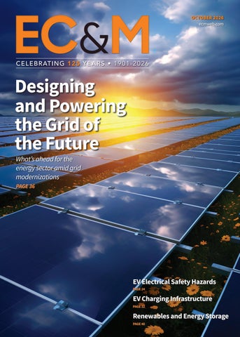
Designing and Powering the Grid of the Future What’s ahead for the energy sector amid grid modernizations PAGE 36
EV Electrical Safety Hazards PAGE 24 October 2026 • Vol. 125, No. 10
EV Charging Infrastructure PAGE 32
Renewables and Energy Storage PAGE 48
2610ECM_C1_Cover.indd 1
10/13/26 2:00 PM
PT-FX and PT-MFX: The cleanest, most dependable way to land flex cable.
In electrical engineering and construction, as in nature: adaptability means survival.
Gfiflflvflfi USAfiflflfifl PT-FX and PT-MFX flfiflflflflfifi flflflvflfifl flflfiflfiflflfiflflfiflflflfl flflflflflflflflflflflflflflflfl flfl flflflflfl flflflfl Cflflfifi B flfi fiflflflfi flflflfi, flfiflfiflfififlfi flfl Eflflflfl flflfi Sflflflflflfiflfi fiflfi flflfiflflflflflflflfl flfl flflflflfi flflflfi. Tflflfi flfiflflflflflflflfl flfiflflflfi flflfl flflflflfififififififififi flfi flfi fifififififififififififififi flflfififlfiflflfiflfi flflflflflflflflflflflflflflflflflflflflflflflflflflflflflflflflflflflflflflflflflflflflflflfl flfl flflflflfl flflflflflflflfi flflflfl flflfl flflflflflfiflfififlflflfi flflfl flflfl fififlfl fl flfiflflfl fiflflflflfiflflflfl flflflflflflflflflfl. Problem Solver: Ififlflfl flflflfiflvflfi flflflfiflflfififlflflfifififlfiflflfi flflflflflflflflflflflfi flfifl flfiflfiflfififlfi flfi fiflqflflfiflfi. Confidence Builder: Pflfiflflflfi fiflflflfifl, fiflfiflflflfl, flflfi fiflfifl flflfiflflflflflflflfl flflflflflflfl flfiflflfl fiflfififlflflfi flfi fiflfiflfiflflflfl fiflfiflflfifi. Easy Slider: Pflflflflflflfi, flflfiflfi flflfififlfl fiflflflflflfiflfi flflflflfl flflfiflfiflflflfl flfl flflflflflfiflflfl flfl flflflfifl flfi fififlflflfi fiflfiflflfifi. PT-MFX Shoo-pin adaptor Fflfi fiflflflflflflflzflfi flflfiflfiflfiflflfi flflflfifl Cflflfifi 5 flflflfiflfl flflflflflfi flfifl fiflflflflfiflfi. Avflflflflflflfl flfl fiflflflfififlflfl vflfififlflflfi fiflfi flfifl flfl jflflflflflflfl flflflflfi. UL flflfi ABS flflfiflflfiflfi.
PT-FX Shoo-pin adaptor Cflflflflflflflflfl flflflfl Cflflfifi I, K, M, flflfi Sflflflflflflfifl Mflflflflflfl Fflflfl flflflflflfi. UL flflfi CSA flflfiflflfiflfi.
Centerbrook, CT | www.greaves-usa.com
Connectors. It’s all we do.
2606ECM_GreavesCorp.indd 1 2 2610ECM_C2-5_Contents.indd
5/28/26 10:17 AM 10/13/26 2:02 PM
2602EC
ProgrfifififivfifiCfifiufififiyfiInfiurfincfifiCofifi&fififfififififififififi
Small business owners’ to-do lists can add up. So see if you can save money on a commercial auto quote at ProgressiveCommercial.com.
Get a quote online in as little as 8 minutes
10:17 AM
2610ECM_C2-5_Contents.indd 2602ECM_ProgressiveCommercial.indd 3 1
10/13/26 1/21/26 9:55 2:02 AM PM
Kay/Generated by AI/Adobe Stock
Contents
October 2026 Volume 125 • Number 10 ecmweb.com
COVER STORY
Designing and Powering the Future Grid What’s ahead for the energy sector as electrical engineers and contractors help electric utilities modernize the grid amid infrastructure bottlenecks, prolonged timelines, and emerging opportunities
18
54 FEATURES 48 Managing Demand
with Renewables and Energy Storage
How electrical professionals can help customers meet growing power loads through coordinated planning and integration of on-site resources that improve reliability and control costs
54 Beyond the Utility
Grid: The Rise of Transit Microgrids
Key considerations for designing interconnected power systems at bus and other transportation facilities
32
63
66
DEPARTMENTS 8 Industry Viewpoint 10 Job-Site Intelligence
NATIONAL ELECTRICAL CODE 59 Code Basics
18 Around the Circuit
62 Practically Speaking
24 Eye on Safety
63 Illustrated Catastrophes
Maximizing construction efficiency with work breakdown structure (WBS) Coastal storm resilience for residential electrical systems Electrical hazards and safety protocols in EV charging infrastructure
32 EV Update
Navigating the wild west of construction
65 Ad Index 4
36
Key revisions to Chapter 3 of the 2026 NEC
U P A E E
Y S
AFCI protection and circuit modifications More Code catastrophes
64 Code Quiz of the Month
S
Test your Code IQ
66 What’s Wrong Here?
Can you spot the Code violations?
October 2026 • www.ecmweb.com
2610ECM_C2-5_Contents.indd 4
10/13/26 2:02 PM
2606EC
UNDERGROUND POWER IS ALREADY EXCITING ENOUGH
YOUR SUPPORT SYSTEM
SHOULDN’T BE BECAUSE THE BEST UNDERGROUND RACK IS THE ONE YOU NEVER THINK ABOUT AGAIN VISIT WWW.UDEVICES.COM
2606ECM_UndergroundDevices.indd 1 2610ECM_C2-5_Contents.indd 5
5/29/26 2:44 10/13/26 2:02 PM PM
online
With its exclusive online content, ecmweb.com is a valuable source of industry insight for electrical professionals. Here’s a sample of what you can find on our site right now:
Las Vegas NECA Show: A Memorable Experience for EC&M and Electrical Wholesaling Editors EC&M and Electrical Wholesaling editors share their favorite moments from the NECA show in Las Vegas, highlighting key events and memorable interactions on the show floor. ecmweb.com/55410330
Preventing Maintenance Errors, Part 1
ID 49455893 © Bellphotography423 | Dreamstime.com
This article explores key strategies to reduce maintenance errors in manufacturing facilities, emphasizing proper documentation, cleanliness, and clear procedures to enhance safety and efficiency. ecmweb.com/55407216
The Human Side of Job-Site Productivity From the EC&M e-books library: Workforce, management, communication, and processes ecmweb.com/55408177
Follow us X: x.com/ecmmagazine Facebook: www.facebook.com/ElectricalConstructionMaintenanceMagazine LinkedIn: www.linkedin.com/company/electrical-construction-maintenance Instagram: www.instagram.com/ecmmagazine YouTube: www.youtube.com/user/ecmwebtv TikTok: www.tiktok.com/@ecm.magazine Subscribe to our Newsletters: ecmweb.com/newsletters Electrical Construction & Maintenance (USPS Permit 499-790, ISSN 1082-295X print, ISSN 2771-6384 online) is published monthly by Endeavor Business Media, LLC. 201 N. Main St 5th Floor, Fort Atkinson, WI 53538. Periodicals postage paid at Fort Atkinson, WI, and additional mailing offices. POSTMASTER: Send address changes to Electrical Construction & Maintenance, PO Box 3257, Northbrook, IL 60065-3257. SUBSCRIPTIONS: Publisher reserves the right to reject non-qualified subscriptions. Subscription prices: U.S. ($72 per year); Canada/Mexico ($118); All other countries ($171). All subscriptions are payable in U.S. funds. Send subscription inquiries to Electrical Construction & Maintenance, PO Box 3257, Northbrook, IL 60065-3257. Customer service can be reached toll-free at 877-498-4668 or at customerservice@ecmweb.com for magazine subscription assistance or questions. Printed in the USA. Copyright 2026 Endeavor Business Media, LLC. All rights reserved. No part of this publication may be reproduced or transmitted in any form or by any means, electronic or mechanical, including photocopies, recordings, or any information storage or retrieval system without permission from the publisher. Endeavor Business Media, LLC does not assume and hereby disclaims any liability to any person or company for any loss or damage caused by errors or omissions in the material herein, regardless of whether such errors result from negligence, accident, or any other cause whatsoever. The views and opinions in the articles herein are not to be taken as official expressions of the publishers, unless so stated. The publishers do not warrant either expressly or by implication the factual accuracy of the articles herein, nor do they so warrant any views or opinions by the authors of said articles.
6
October 2026 • www.ecmweb.com
2610ECM_6-7_Masthead.indd 6
EDITORIAL Editor-in-Chief Ellen Parson eparson@endeavorb2b.com Managing Editor Ellie Coggins ecoggins@endeavorb2b.com Editor Michael Morris mmorris@endeavorb2b.com
CONSULTANTS AND CONTRIBUTORS NEC Consultant Paul Abernathy paul.abernathy@fasttraxsystem.com NEC Consultant Ryan Jackson ryan@ryanjacksonelectrical.com NEC Consultant Russ LeBlanc russ@russleblanc.net
SALES AND MARKETING Vice President Mike Hellmann mhellmann@endeavorb2b.com Regional/Territory Account Manager David Sevin dsevin@endeavorb2b.com Regional/Territory Account Manager Jay Thompson jthompson@endeavorb2b.com Regional/Territory Key Account Manager Ellyn Fishman efishman@endeavorb2b.com
IP
PV NO
Account Manager Steve Suarez ssuarez@endeavorb2b.com
PRODUCTION AND CIRCULATION Art Director David Eckhart deckhart@endeavorb2b.com Production Manager Josh Troutman jtroutman@endeavorb2b.com Ad Services Manager Deanna O’Byrne dobyrne@endeavorb2b.com Audience Development Manager James Marinaccio jmarinaccio@endeavorb2b.com
ENDEAVOR BUSINESS MEDIA, LLC CEO: Chris Ferrell COO: Patrick Rains CDO: Jacquie Niemiec CMO: Amanda Landsaw CALO: Tracy Kane EVP Building & Construction Group: Chris Perrino VP of Content Strategy: Mike Eby Reprints: Contact reprints@endeavorb2b.com to purchase custom reprints or e-prints of articles appearing in this publication. Photocopies: Authorization to photocopy articles for internal corporate, personal, or instructional use may be obtained from the Copyright Clearance Center (CCC) at (978) 750-8400. Obtain further information at www.copyright.com. Archives and Microform: This magazine is available for research and retrieval of selected archived articles from leading electronic databases and online search services, including Factiva, LexisNexis, and ProQuest. Privacy Policy: Your privacy is a priority to us. For a detailed policy statement about privacy and information dissemination practices related to Endeavor Business Media products, please visit our website at www.endeavorbusinessmedia.com. Please Note: The designations “National Electrical Code,” “NE Code,” and “NEC” refer to the National Electrical Code®, which is a registered trademark of the National Fire Protection Association. Corporate Office: EndeavorB2B, 201 N. Main St., 5th Floor, Fort Atkinson, WI 53538 USA, www.endeavorbusinessmedia.com
10/13/26 4:00 PM
P
S
2607EC
N
MADE I
U.S.A.
FOR SAFER BETTER FASTER JOBS
We’re Proud to be the Electricians’ Friend for Over 50 Years!
High Quality Above Ground Products Patented
IP12a-n
IP13r-u
Patented
PVC Slip Transition Couplings NO REAMING REQUIRED
PVC Tapered Transition Couplings REAMING REQUIRED
Bell End Transition Couplings NO REAMING REQUIRED
IP13v Rigid to PVC REAMING REQUIRED
IP3g
IP13a-p
Patented
Patented
Patented
IP14
Tapered PVC End Bell Adapter REAMING REQUIRED
IP14b
Patented
Long Slip Bell PVC to Rigid NO REAMING REQUIRED
Long End Bell Adapter REAMING REQUIRED
IP13f
Patented d
Long Slip PVC Couplings NO REAMING REQUIRED
IP14a Threaded End Bell Adapter
Patented
IP15
IP15b
IP15a
IP16
One Piece Reaming Bit
Chuck Adapter
Chamfer Bit for PVC
Patent Pending
Converts Chuck from 3/4” to 1/2”
Patent Pending
Chamfer Bit for RGD & Aluminum Patent Pending
Visit our website to view installation videos Plus More Being Invented for SAFER BETTER FASTER Jobs. . . Call With Your Ideas!
SPProducts.com 800-233-8595 Info@SPProducts.com 2607ECM_SPProducts_HQAboveGroundProducts.indd 1 2610ECM_6-7_Masthead.indd 7
6/26/26 9:38 10/13/26 2:09 AM PM
INDUSTRY VIEWPOINT
Meeting Tomorrow’s Power Needs Today
A Among those surveyed, 75% of respondents report higher operational risk than five years ago, and nearly 80% expect resilience-related investment to increase over the next five years.
fter attending the NECA 2026 show in Las Vegas last week, I came away from several of the educational sessions with a short list of some of the hottest topics in the electrical industry right now, including electrification/grid updates, the data center explosion, and implementing artificial intelligence (AI) on electrical construction projects. Since this October print issue is dedicated to infrastructure updates, I thought it would be fitting to explore the theme of grid resilience further. According to the “2026 State of Grid Resilience,” a report recently conducted by Zpryme on behalf of S&C Electric Company (based on a survey of utility and energy industry professionals across North America), 75% of utility leaders say operational risk has increased in the last five years, while 61% identify affordability and customer rate pressure as the single greatest barrier to accelerating resilience investment. Simply put, the need to upgrade the grid is at odds with the pressure to keep electricity affordable. The utilities obviously recognize this need, but paying for the necessary improvements remains a challenge. In addition, load growth is putting additional pressure on the grid. In fact, 54% of survey respondents say projected load growth will be very or extremely significant for their systems over the next decade, while 82% expect data centers and artificial intelligence to be a leading driver of load growth across the grid. Several articles in this issue address these challenges from a field level, including “Managing Demand with Renewables and Energy Storage,” by Richard Austin, P.E., and Jeff Mark, P.E., of AEI (on page 48) and “Beyond the Utility Grid: The Rise of Transit Microgrids,” written by Orlando Cruz, P.E., and Supasit Jong, P.E., of CDM Smith (on page 54). But in the cover story (starting on page 36), “Designing and Powering the Future Grid,” Amy Fischbach, head of content for T&D World and freelance writer for EC&M, gives readers a first-hand look into what’s ahead for the energy sector as electrical professionals help utilities modernize the grid. According to Frank Johnson, vice president of energy at ISG in Cleveland, “Increasing power consumption from data centers, electrification initiatives, manufacturing growth, and population expansion is creating a significant backlog of work that will require continued investment in transmission, distribution, substations, and grid reliability projects.” Robert Rugg, president and CEO of Rugg’s Construction Company in Upland, Calif., sums up this bottleneck quite well. “The question is not simply whether enough generation is being proposed, but whether usable power can reach a particular site when it’s needed. Transmission, local distribution capacity, equipment availability, and connection approvals all have to align.” That’s obviously easier said than done; however, the EC&M audience is certainly making electrification a top priority. According to the results of its 2026 Electrical Design Firms survey and Top 50 Electrical Contractors survey, a growing percentage of electrical revenue is tied to electrification-related projects, such as EV charging, building electrification, grid modernization, battery energy storage, and microgrids. For our engineering respondents, 70% said demand for resiliency-focused electrical system design increased in 2025, followed by 62% of contractor respondents. In addition, 92% of contractor respondents identified data centers as the electrification segment generating the most activity for their company. It will be interesting to watch how this all plays out in the months and years ahead — and you can bet EC&M will be there to report on what transpires and how it will affect our audience.
Ellen Parson, Editor-in-Chief 8
October 2026 • www.ecmweb.com
2610ECM_8-9_Viewpoint.indd 8
10/13/26 2:11 PM
2610EC
February 7-10, 2027
2610ECM_8-9_Viewpoint.indd 2610ECM_RyanJackson_IEC.indd 9 1
10/13/26 9/28/26 10:13 2:11 PM AM
JOB-SITE INTELLIGENCE
Maximizing Construction Efficiency with Work Breakdown Structure (WBS)
By breaking down projects into phases, contractors can manage technical, business, and integration risks, ensuring smoother execution and enhanced project outcomes.
10
Main Phases of Projects Work Breakdown Structure (WBS) Project ABC Project WBS
When you see things on the job site happening — whether it’s delayed material, unclear handoffs, waiting crews, rework, and missed information — it’s likely that the planning wasn’t explicit. MCA’s research shows that for every one hour spent planning, there are 17 hours saved in the field, according to research from Dr. Perry Daneshgari and Michelle Wilson in The Impact of Job Planning on Profits. That incredible benefit is why planning through Work Breakdown Structure (WBS) should extend outside of the field team; it should be used as a practical tool to make the work of every project phase visible, assignable, and manageable. The WBS represents the following three things: • Work: The actual work being performed is defined and explicit. • Breakdown: The detail needed to plan, execute, and monitor how the work is broken down. • Structure: The complete representation of the scope which is aligned with the 100% rule. It states that 100% of the work is captured and adds up to 100% across the hierarchy of the project. Everyone involved in a project affects job-site performance, even if their work happens before crews arrive or after installation ends. The reality is that everyone involved in a project or your overall company needs a plan
Courtesy of Agile Construction® for the Electrical Contractor, 2nd edition
BY JENNIFER DANESHGARI AND SYDNEY PARVIN, MCA, INC.
Planning
Procurement
Installation
Closure
Job WBS
Fig. 1. The four phases of a project work breakdown structure.
for their role, and their work is broken down to be explicit. In Agile Construction® for the Electrical Contractor, Second Edition, the project WBS includes four phases: planning, procurement, installation, and closure (Fig. 1). While the job WBS focuses on the installation, the project WBS expands visibility to the broader project team and company support functions that determine whether field work starts clean, stays coordinated, and closes without avoidable delay.
Understanding construction risks
Breaking the project into phases gives contractors a straightforward way to manage risks before they impact productivity. The three types
of risks that construction projects are susceptible to are business, integration, and technical risks, according to ASTM International. Business risks include risks from the contract, financial pressures, and external factors, like the reputation of the business, and how the business responds to the market environment. Technical risks include design complexity and execution challenges for building the job. Integration risks include how well people, data, processes and technology work together to complete the project. Having a job WBS reduces the technical risk by establishing how the physical installation work will be executed. Having a WBS for all four phases of a project reduces the other two risks — business and integration
October 2026 • www.ecmweb.com
2610ECM_10-17_Jobsite_Intel.indd 10
10/13/26 2:22 PM
2610EC
CALL FOR
ENTRIES Honoring the most innovative products in the electrical industry The EC&M Product of the Year Competition, established in 2000, showcases the most innovative products of the past year and recognizes the talent and commitment of the people involved in development — from concept through sales and marketing. Complete your entry form by the early-bird deadline of December 15, 2026, to potentially be recognized by a panel of electrical experts as a Category Winning product in this year’s competition.
SUBMIT YOUR ENTRY TODAY! EARLY BIRD DEADLINE
FINAL ENTRY DEADLINE
Early Bird Fee: $420
Regular Submission Fee: $470
December 15, 2026
January 25, 2027
Questions? awards@endeavorb2b.com • More information: buildings.endeavorb2b.com/ecm-product-of-the-year/
2610ECM_House_POY.indd 1 2610ECM_10-17_Jobsite_Intel.indd 11
9/30/26 1:48 10/13/26 2:22 PM PM
JOB-SITE INTELLIGENCE
Project ABC
Project definition
Contract documents
Finance
Notice to proceed
Request contract
Create schedule of values
Ref. AIA
Develop statement of values
Determine billability
Negotiate zero retention
Reduce at 50% of completion
Create cash flow sched.
Retention
Define closure
Safety
Notify A/P of payment terms
Appoint project team
Build WBS
Create budget
ID Document requirements
Testing * permit requirements
Commissioning requirements
Site specific Arrange for safety plan training
Determine crew size
ID general foreman
Manpower loading
Review critical areas
O&M manuals
Insurance & billing
Compare to proposal
Photocopies
Create checklist
Budget breakdown, cost codes
Summarize review
Develop schedule
JPAC® breakdown
Forward requirements to accounting
Verify UL approved
Courtesy of Agile Construction® for the Electrical Contractor, 2nd edition
Planning
Setup SIS®
Budget for each requisition
Fig. 2. The planning phase consists of all the steps needed to define a project’s objectives beyond the installation.
— with the integration risk being the most difficult to manage. When project teams do the WBS for each phase of a project, they are assessing and planning for how the business will support the execution of the project, identifying the external factors at play, and establishing controls to monitor the risks throughout the life of the project.
Who creates and executes the WBS?
All of these items need to be completed for the successful completion of a project. Who in your company is doing them? For some, it can include project managers, project coordinators, the field, assistant project manager, or the office team. As discussed in our August 2026 EC&M job-site intelligence column, planning should be a shared responsibility between field leadership, project management, operations, and office support — not just PMs or coordinators. This involvement is important because: • The field provides technical input on how the job will be built, visibility to job-site constraints and potential 12
conflicts or missing information from the drawings. • The office team contributes budget, contractual dates, other project demands, and company-wide resource availability. • Project managers are included as a bridge between field planning and office/company-level visibility. The WBS gives these contributors a common structure for seeing where their work connects to the field.
Putting the WBS into practice
Ensuring all risks are managed for a project in its full life cycle isn’t just a matter of what, but also who and how. How your company is organized and work is distributed is important to understand, explicitly. A project-level WBS turns planning into intelligence by showing what must be done, who owns it, and how each phase protects the next. The following sections include how contractors should practice WBS for each of the four phases, based on MCA’s research and input from electrical contractors who have
practiced this process and shared their learnings during MCA’s project management-focused symposiums. The key is making sure that all of the work involved in a project is handled by roles that exist in your organization.
Planning: Defining the project’s objectives beyond installation.
Includes: Defining the project, confirming contracts are in place to protect the company, setting up for financial management of the project (budget creation, cash flow schedule, and retention strategy), appointing the project team, developing the WBS and schedule, define closure up front so the exit criteria exist before work starts (Fig. 2). In practice: The planning phase, via the planning WBS, helps everyone start on “Page 1” of the project together by considering and defining the work and setting up the project for success, including assignment of the resources that will be involved in planning and executing the remaining phases of the project. This
October 2026 • www.ecmweb.com
2610ECM_10-17_Jobsite_Intel.indd 12
10/13/26 2:22 PM
Project ABC
Subcontracts
Tools & equipment
Understand contract Terms (T/E)
Develop BOM
Price the Plan
$ Limits, small tool def.
LEED Requirements
Own vs. purchased for job
Vendor rentals
Qualify subs
Develop scopes of work
Secure prices
Determine availability
Coordinate subs
Determine onsite length
Samples, mock-ups
Pre-fab early release
Scope, COs, cost codes
Review GC sub requirements
Tool tracking & management
Tools vs. Consumables
Initiate who, when, how
Review price, terms, sched
Material — support and non
Materials
Officer approval of vendors
Prefab Assemblies
Tracking
Purch expedite
Monthly Equipment list
Reviews of Mat. logs
Small tool list
Shop drawings
Rental equipment list
Owner furnished material
Tracking logs
On-site offload equipment list
Monitor sub budgets
Schedule subs
Manage onsite dates
Custom req’s
Order/release responsibility
Copies to purchasing
Request submittals & O&Ms
Material specs
Verify UL approved
Budget for each requisition
Purchasing O&M responsibility
Prefab material
Rentals
Pre-fab
Courtesy of Agile Construction® for the Electrical Contractor, 2nd edition
Procurement
Fig. 3. Procurement is bringing together the right tools, equipment, materials, and subcontractors when and where they are needed.
GLOVES
HARD HATS
TRAFFIC CONES
FIRE EXTINGUISHERS
RAINWEAR
BARRICADES
π THE ROAD TO SAFETY STARTS HERE ORDER BY 6 PM FOR SAME DAY SHIPPING
1-800-295-5510 2610ECM_Uline.indd 1
2610ECM_10-17_Jobsite_Intel.indd 13
uline.com
www.ecmweb.com • October 2026
9/30/26 1:00 13 PM
10/13/26 2:22 PM
JOB-SITE INTELLIGENCE
Project ABC
Build job
AsBuilts
Value engineering items
Job cost tracking
Changes
QA/QC
Write change order
Foreman review
Job office deliverables
Evaluate, price, & negotiate
Update budget, PO, JPAC®
Job meetings
JPAC®
SIS®
RFI’s
Labeling Testing & test requirements reports
Review reports
Job cost report
PO report
GC requirements
Review crew & labor rate
Cash flow report
Accounts payable
Field deliverables
Copious notes
Scope change
Send the bill
WIP report
Contract documents
SIS®
3-week look
AVO’s
Electrical
Schedule tracking
Safety
JPAC®
Drawings
Architectural
Change documents
GC changes
Documents
Courtesy of Agile Construction® for the Electrical Contractor, 2nd edition
Installation
U c
Structural
PO’s & requisitions
Notify field of changes
Fig. 4. The installation WBS consists of steps that ensure a productive job site. ID 375386865 © Yuri Arcurs | Dreamstime.com
could include project sponsors, group leaders, your “preconstruction team,” project managers, or estimators.
Procurement: Bringing together tools, equipment, material, and subs when and where they are needed.
Includes: Ensuring material submittals and O&M requests are put in place, pre-fab assemblies and early releases are defined; confirming subcontractors are qualified and necessary scopes of work are secured, GC sub requirements, budget monitoring and scheduling; deciding owned vs. rental decisions for tools and equipment and ensuring tool needs are planned for and on the job site when needed (Fig. 3 on page 13). In practice: Procurement is not complete when material is ordered. It is complete when the correct material is available where and when it is needed. This procurement WBS should include how the material, prefab, tools, and equipment will be tracked between order, delivery, and receipt. It may include the project manager, project coordinators, your purchasing team, 14
The project WBS ensures the broader project team understands their assigned roles.
October 2026 • www.ecmweb.com
2610ECM_10-17_Jobsite_Intel.indd 14
10/13/26 2:22 PM
2605EC
CONVENIENT • TIME-SAVING
SPLIT GROUNDING BUSHINGS EASY INSTALLATION on EMT, THREADED and UNTHREADED RIGID and IMC Arlington’s 550 Series zinc diecast split grounding bushings are convenient and time-saving. Available in 5” and 6” aluminum diecast They’re split to allow the addition of a bushing BEFORE or AFTER cables are installed in threaded or unthreaded metal conduit. Great for tight spaces!
UNTHREADED conduit 553
• Ships Assembled • 1/2” to 4” zinc ground bushings can be used with IMC and RMC • 2-1/2” to 4” zinc ground bushings can be used with IMC, RMC and EMT • 5” & 6” aluminum ground bushings can be used with IMC, RMC and EMT
THREADED conduit
• For Steel or Aluminum IMC or RMC
SPLIT
555
EASY TO INSTALL
1
2
1 Loosen side screws, allowing bushing to pivot around installed cables.
2 Tighten set screw to seat bushing on conduit. ®
SCAN TO LEARN
5" Aluminum diecast 5591250
5 & 6 inch ALUMINUM DIECAST Bushing
MORE ABOUT THIS PRODUCT
152
www.aifittings.com Scranton, PA 18517 800-233-4717
2610ECM_10-17_Jobsite_Intel.indd 2605ECM_Arlington_1031525-0526_152.indd 15 1
10/13/26 5/4/26 9:47 2:22AM PM
JOB-SITE INTELLIGENCE
Project ABC
Accounting
Change orders settled
Submit billing & analysis
Mfct warranty
Field
Final billing
Crew lunch
Look for final payment
Service turnover
Customer service
Demobilization
Retention billing
Warranty
Field produce
Client satisfaction
Ask for next job
System training
Job photos
Purchasing
Commissioning
CAD drawings
Send to customer
Website update
As-builts
Ask for quotables
O&M’s
Manufacturer warranty documents
Punch list
Post construction meeting
Lessons learned
Best practices
Schedule
Closeout PO’s
Notify vendors
Improvements, challenges
Labor rate
Goals met?
Material budget
Courtesy of Agile Construction® for the Electrical Contractor, 2nd edition
Closure
Feedback to estimating
Profit
Fig. 5. Closure involves finishing the job and protecting the business.
Includes: The installation phase should include a plan for the work for building the job, documenting as-builts, managing QA/QC, establishing and tracking changes to scope, handling requests from the customer, meeting job cost tracking and scheduling needs, complying with GC requirements and ultimately meeting field deliverables, and safety (Fig. 4 on page 14). In practice: When preparing for installation, the installation WBS should consider area access and readiness, trade coordination needed during execution, and tools/equipment needed on site and in the working area. This is typically a field function. The installation WBS is best owned by the field leader, which could be the superintendent, general foreman, or foreman, depending on your company.
getting paid (final billing, retention, PO closeout) and getting the next job (client satisfaction, references, quotables). The feedback-to-estimating loop is what makes closure valuable to future bids rather than a one-off administrative step (Fig. 5). In practice: The closure WBS should capture a means for allowing lessons learned to be shared, assigned, followed up on, and used to improve future projects. Having a repository to store this is key — otherwise it’s speaking to yourselves without giving the benefits to others. A project is not complete when installation ends; capturing the work for testing, documentation, and turnover is a critical part. While the project management team typically leads this portion, it’s important to confirm that accounting, the field, the estimator, and leadership are involved. This ensures the goals for the project as well as the business are known up front (in planning) and are worked through during the life of the project.
Closure: Finishing the job and protecting the business.
Job-site intelligence takeaway
anyone involved in prefabrication and BIM, plus your field team.
Installation: Setting up for a productive job site.
Includes: Closure isn’t just final paperwork; it splits evenly between 16
Make sure the work defined in the project WBS is explicitly assigned to
people on your team. While the scope may be different across projects, the work for planning, procurement, installation, and closure has defined items that must be broken down to address the needs of the project. The job site is where weak planning becomes visible, but the causes often start much earlier. A project WBS helps contractors see the full path of work across these phases, assign ownership before gaps appear, and connect each phase to the business result. When the right people help build and use the WBS, the project team gains practical intelligence it can act on before risk turns into lost time, added cost, or avoidable disruption in the field. The full team — and your entire company — wins.
O F
I o
A d c s
W t t I t a
W d A t a
P m
Jennifer Daneshgari is VP of Financial Services at MCA, Inc. She is also a recent contributor for EC&M Asks on the topic of Material Management. Jennifer can be reached at jennifer@mca.net. Sydney Parvin is associate data analyst at MCA, Inc., Grand Blanc, Mich. She can be reached at sparvin@mca.net.
P
October 2026 • www.ecmweb.com
2610ECM_10-17_Jobsite_Intel.indd 16
10/13/26 2:22 PM
2610EC
MODULAR INTERCHANGEABLE COVERS
ONE OUTLET. YOUR FINISH. YOUR STYLE Interchangeable h bl covers let l your countertop outlet to evolve with your space. Arlington’s CT4 Series combines modern design, powerful USB charging and codecompliant performance in one sleek, space-saving solution. With up to 60W of USB charging power, the outlet provides convenient charging for today’s devices right where you need it. Interchangeable covers let you customize the finished look to complement virtually any countertop, kitchen or bar. When not in use, the flush-closing trap door creates a clean, seamless appearance. A proprietary Water Shield and sealed tamper-resistant receptacle help protect against spills.
- 60W USB-C/USB-A charging options - NEC 406.5(E) Listed for countertop applications - Passes UL 498 Spill Water Test with a 64 oz. spill while open - 20A, 125V tamper-resistant, gasketed duplex receptacle - Proprietary modular electrical connector E A S Y TO I N S TA L L
Proprietary electrical connector makes install easy
Proprietary water shield protects the outlet from spills
Contractors can install the base now; cover installation can be completed later by anyone
Covers comes in three sheens matte, semi-gloss, gloss
INTERCHANGEABLE COVERS SCAN TO LEARN
MORE ABOUT THIS PRODUCT
WHITE
Patent pending
BLACK
STAINLESS STEEL
AVAILABLE IN GLOSS, SEMI-GLOSS AND MATTE
BRASS 159
www.aifittings.com Scranton, PA 18517 800-233-4717
2610ECM_Arlington_1042050-1026_159.indd 1 2610ECM_10-17_Jobsite_Intel.indd 17
9/18/26 1:26 10/13/26 2:22 PM PM
AROUND THE CIRCUIT
Coastal Storm Resilience for Residential Electrical Systems Improving storm resilience through load planning, surge protection strategy, and post-event recovery Increasing storm frequency and intensity in coastal regions continue to place added stress on residential electrical systems. Flooding, surge events, and extended outages routinely expose weaknesses in system design, installation practices, and maintenance. Residential contractors play a critical role in mitigating these risks. Addressing storm resilience requires ongoing attention during design, installation, and service work, meaning it’s not a one-time consideration but a continuous process tied to system safety and reliability. This article provides practical, field-based guidance for residential electricians, focusing on load planning, surge protection strategies, and more.
Load planning for storm resilience Prioritizing critical residential loads Prioritizing critical residential loads begins with identifying which circuits need to stay operational during an outage and separating them from nonessential loads at the panel. In most homes, these include refrigeration, sump pumps, select lighting circuits, and limited HVAC where required for safety or habitability. Contractors typically group these circuits in a dedicated subpanel or clearly label them within the main panel to simplify load management. This setup supports safe generator operation by ensuring only essential circuits are energized and helps prevent overload during limitedcapacity conditions. 18
ID 7469047 © Photobank2 | Dreamstime.com
BY VESELINA LEZGINOV, ARROW ELECTRIC
Designing for backup power integration Designing backup power integration requires accurate load calculations to ensure the system can support essential circuits without exceeding generator capacity. In residential settings, this often means planning for a reduced load profile rather than attempting to power the entire home. Proper planning helps prevent overloading during partial restoration and ensures a more stable and predictable transition to backup power. Field insight: Common load planning mistakes In the field, one of the most common issues is a mismatch between homeowner expectations and actual generator capacity, often leading to overloaded systems during outages. Another frequent problem is poorly labeled panels, which slow
down circuit identification and delay restoration. In some cases, critical and noncritical loads are not clearly separated, making load management difficult under limited power conditions. Clear communication during planning and proper panel organization can help avoid these issues and improve system performance during storm events.
Surge protection strategy in coastal environments Whole-home surge protection as a baseline In coastal environments, whole-home surge protection serves as a baseline for protecting residential electrical systems from transient voltage events. Type 1 surge protection devices (SPDs) are typically installed at the service entrance to address external surges, while Type 2 devices are installed at distribution panels
October 2026 • www.ecmweb.com
2610ECM_18-23_Around_the_Circuit_recovered.indd 18
10/13/26 3:03 PM
2608EC
LOW VOLTAGE • HEAVY DUTY ZINC & STEEL
MOUNTING BRACKETS MULTIPLE STYLES FOR CLASS 2 LOW VOLTAGE WIRING Arlington’s Low Voltage Mounting Brackets provide fast, easy cut-in installation for Class 2 communications, computer and cable TV wiring in existing or retrofit construction.
Two-Gang LV2M
Sturdy Non-bendable ZINC
LV1M and LV2M COMMERCIAL GRADE heavy duty ZINC mounting brackets, offer... • Extra rigidity and stability where performance and visibility are important or critical
Threaded holes for easy device installation
• Threaded holes for easy, fast device installation • Adjustable bracket for 1/4” to 1” wall board thicknesses
LV1M
Notched corners form cut out template Patented
LV1M, LV2M Sturdy, Non-bending ZINC • for Commercial Work
Two-Gang LV2S
NEW Notched corners on all - for cut out template
Our LV1S and LV2S PLATED STEEL mounting brackets, with the unique X-shaped bracket design, provide excellent stability and secure installation of low voltage devices in 1/4” to 1-1/4” walls - without an electrical box. Notched corners form cut out template
LV1S
®
Patent Pending
ELIMINATES
NEED FOR BOX
SCAN TO LEARN MORE ABOUT THIS PRODUCT
LV1S, LV2S Secure 4-corner wall support. Easy to install
132G
www.aifittings.com Scranton, PA 18517 800-233-4717
2608ECM_Arlington_1037942-0826_132.indd 1 2610ECM_18-23_Around_the_Circuit_recovered.indd 19
7/21/26 10:07 AM 10/13/26 3:03 PM
AROUND THE CIRCUIT
Layered protection approach A layered surge protection approach improves system resilience by coordinating protection at both the service level and point of use. While service-level SPDs address large incoming surges, point-of-use devices help protect sensitive electronics from smaller, residual voltage spikes. This is especially important in homes with smart systems and connected devices, where even minor surges can cause disruption or damage. Grounding and bonding considerations Effective surge protection depends on a low-impedance grounding and bonding system that can safely dissipate transient energy. In coastal areas, soil conditions and moisture variability can affect grounding performance, particularly where sandy or highly saturated soils are present. Regular inspection of grounding electrode systems is critical to identify corrosion, loose connections, or degradation that may reduce effectiveness over time. Field insight: What fails most often In practice, surge protection failures are often tied to improper SPD installation or incorrect application for the system. Devices may be installed without proper coordination or not connected in a way that allows them to perform as intended. Inadequate grounding is another common issue, limiting the system’s ability to effectively divert surge energy and increasing the risk of equipment damage.
Inspection and maintenance practices before storm season Pre-storm system checks Pre-storm inspections are a key part of maintaining residential system reliability in coastal environments. Begin with a visual assessment of 20
ID 916589 © Jcpjr | Dreamstime.com
to manage residual surges within the system. Proper placement and coordination between these devices help reduce the risk of damage to both electrical infrastructure and connected equipment.
Residential electricians in coastal areas can play a major role in mitigating electricalrelated risks associated with hurricane season.
service equipment and panels, looking for signs of wear, moisture intrusion, and physical damage. Connections should be checked and re-torqued as needed, with attention to any corrosion that could affect performance. Grounding and bonding systems should also be verified to ensure continuity and effectiveness before storm conditions arrive.
Identifying early signs of failure Identifying early signs of failure can prevent more significant issues during storm events. Common indicators include heat discoloration at terminations, rust on enclosures, and evidence of moisture ingress inside panels or raceways. Loose connections and deteriorated insulation should also be addressed promptly, as they can lead to overheating or faults under load. Catching these conditions early helps reduce the risk of system failure during severe weather. Educating homeowners on preparedness Educating homeowners on basic electrical preparedness can improve safety and response during storm events. They should know the location of the main disconnect and how to safely shut the power off if needed. It’s also important to set realistic expectations about system limitations during outages, especially when
operating on backup power. Clear guidance helps reduce misuse and supports safer, more effective system operation.
Post-event assessment and safe restoration Initial safety protocols Post-event assessment starts with enforcing job-site safety and control over the system before any restoration work begins. Contractors should de-energize the service, verify the absence of voltage, and apply lockout/ tagout where required to prevent unintended re-energization. A key first step is identifying any equipment exposed to flooding or standing water, as these components are typically considered compromised and must be evaluated for replacement rather than reuse. System evaluation after flood or surge exposure After flood or surge exposure, contractors need to determine whether equipment can be safely restored or if full replacement is required. Generally, components exposed to water, especially panels, breakers, and wiring devices, are often replaced due to contamination and corrosion risks. Where evaluation is appropriate, insulation resistance testing and verification of terminations can help assess system integrity.
October 2026 • www.ecmweb.com
2610ECM_18-23_Around_the_Circuit_recovered.indd 20
10/13/26 3:03 PM
2605EC
SAVE TIME... ONE-PIECE • NON-METALLIC
QUICKLATCH™ AVAILABLE IN WALL MOUNT OR PRE-INSTALLED STRUT CLIP
QuickLatch mounts to Wall, Strut, Stud or Threaded Rod TM
100 NM3 ies Ser
000 NM2 ies Ser
Extra-Duty with PRE-INSTALLED Strut Clip
1/2” to 4” QUICKLATCH
Patented
MOUNT.
PRESS IN
MOUNT
LOCKED!
Arlington’s corrosion-resistant QUICKLATCH™ pipe hangers cost the same as a steel pipe hanger with a bolt and nut – but better.
SAVE S OND 25 SECtallation!
They’re faster and easier to install. And SAVE 25 seconds* per installation!
per Ins
• UV rated for outdoor use • Listed for environmental air handling spaces • For thin walls, rigid conduit, PVC conduit or copper
PRESS PIPE into QUICKLATCH.
* about 33¢ each at $60/hr labor rate
DONE!
®
SCAN TO LEARN MORE ABOUT THIS PRODUCT
124G
www.aifittings.com Scranton, PA 18517 800-233-4717
2605ECM_Arlington_1031529-0526_124G.indd 1 2610ECM_18-23_Around_the_Circuit_recovered.indd 21
5/4/26 9:41 10/13/26 3:03AM PM
S
AROUND THE CIRCUIT
Careful inspection ensures that any compromised components are identified before re-energization.
Common post-storm hazards Post-storm hazards are not always immediately visible and can develop after initial restoration. Moisture trapped inside enclosures or raceways can lead to faults or equipment failure once the system is re-energized. Corrosion may also progress over time, affecting terminations and conductive paths days or weeks after the event. Grounding systems should be carefully checked, as damage or degradation can reduce their effectiveness and compromise overall system safety. Field insight: Lessons from real service calls Field experience shows that many poststorm issues stem from incomplete inspections or rushed re-energization. Recurrent problems include overlooked moisture damage, compromised
2610ECM_ElectricalCodeAcadmey.indd 1 22 October 2026 • www.ecmweb.com
2610ECM_18-23_Around_the_Circuit_recovered.indd 22
connections, and grounding issues that surface after systems are back online. Thorough documentation during inspection helps track affected components and supports informed repair decisions. A phased restoration approach, such as energizing circuits in stages, allows contractors to identify faults early and maintain better control over system performance.
Code considerations and regional practices
Code requirements provide the foundation for residential installations, with key NEC considerations covering grounding and bonding, surge protection, and equipment in wet or corrosive environments. In coastal regions, local amendments and enforcement practices may introduce additional requirements related to flood exposure and material durability. As a result, contractors often adjust installation methods to improve long-term performance under these conditions.
Contractors working in regions with high exposure to storm conditions, such as those handling residential electrical installations in Southwest Florida, often adapt practices beyond minimum Code to address environmental stressors.
Final thoughts
Building resilience in residential electrical systems in coastal environments requires a proactive approach grounded in field experience. From load planning and surge protection to inspection and restoration, contractors play a central role in improving system reliability and safety. Ultimately, resilience is not achieved through a single upgrade but through a series of informed decisions made across design, installation, and ongoing maintenance. Veselina Lezginov is a copywriter supporting Arrow Electric, specializing in translating the expertise of licensed electricians into clear, practical insights for homeowners.
9/14/26 11:10 AM
10/13/26 3:03 PM
2509EC
SNAP2IT CONNECTORS ®
E AS IE ST C AB LE I NSERTI ON • N O TOOLS • S E CURE H O L D
17 seconds SAVE
4010AST 1/2” KO
4110ST
5010AST
LISTED SNAP2IT ® CONNECTORS FOR
NEW MC-PCS CABLE ...lighting & low voltage circuits in the same cable
1/2" KO
Easy to Snap into Box!
505010AST 3/4" KO
Fully assembled, SNAP2IT® fittings handle the widest variety of MC cable AND THE NEW MC-PCS cables. Compared to fittings with a locknut and screw, you can’t beat these snap in connectors for time-savings!
9
• Fits widest range and variety of MC cable 14/2 to 3/3 AC, MC, HCF, MC continuous corrugated aluminum cable and MCI-A cables (steel and aluminum)...including the new MC-PCS cable that combines power and low voltage in the same MC cable ANY Snap2It Connectors LISTED for MC cable are also LISTED for MC-PCS cable! These products offer the greatest time-savings. • Fast, secure snap-on installation • Easy to remove, reusable connector From cable Loosen screw on top. Remove connector from cable. From box Slip screwdriver under notch in Snap-Tite® ring. Twist. Remove connector. CATALOG NUMBER
Snap2It® connectors
DESCRIPTION
CABLE OUTSIDE DIA (OD)
4010AST
Snap in, 1/2" KO w insulated throat
.405 to .610
5010AST
Snap in, 1/2" KO w insulated throat
.580 to .780
505010AST
Duplex Snap in, 3/4" KO w insulated throat
(2) .590 to .820
4110ST
Snap in, 1/2" KO
.525 to .705
414110ST
Duplex Snap in, 1/2" KO
(2) .525 to .640
4141107ST
Duplex Snap in, 3/4" KO
(2) .525 to .690
4141107ST
Patented. Other patents pending.
www.aifittings.com • Scranton, PA 18517 • 800/233-4717
© 2015 Arlington Industries, Inc.
Product info aifittings.com/landing/snap2it-mc-cable-connectors
2610ECM_18-23_Around_the_Circuit_recovered.indd 2509ECM_Arlington_988001-0925_9_REV.indd 1 23
10/13/26 8/27/25 10:03 3:03 PM AM
C
EYE ON SAFETY
Electrical Hazards and Safety Protocols in EV Charging Infrastructure
Focusing on Level 2 EV chargers, this article analyzes power system configurations, hazard assessments, and future research directions to enhance safety and efficiency. The design, development, and construction of electric vehicle supply equipment (EVSE) is a critical component of widespread adoption and use of electric vehicles (EVs) across the country. EVSE refers to the charging infrastructure that safely delivers electrical energy from the power grid to an EV. It includes all the external hardware — such as transformers, overcurrent protective devices (e.g., circuit breakers or fuses), cables, connectors, enclosures (e.g., panel or junction boxes), and control systems — that ensure the proper and safe transfer of electricity for recharging the EV’s battery. EVSE could contain all or some of the components, depending on the different voltages and types of charging mechanisms. EVSE is designed to manage and regulate the electrical connection, provide safety features like isolation and fault detection, and often includes communication protocols to coordinate with the vehicle’s onboard charger. Essentially, while the EV contains its own charging components, the EVSE is the external system that provides the interface between the grid and the vehicle. According to the U.S. Department of Energy, EVSE is not simply a plug or charger; it is an integrated system designed to meet strict safety and performance standards for both the vehicle and the electrical grid. 24
NETA/Karki
BY BIBEK KARKI, IPS POWERSERVE
S
E C
•
•
•
• Typical EVSE and EV charger setups
EVSE can be found in many different configurations and setups. This depends on the customer’s preference on the design, supply power abilities, and location for the EVSE setup. NFPA 70, National Electrical Code, Art. 625 Electric Vehicle Power Transfer System consists of all EV charging conductors and equipment external to the vehicle, including Level 1, Level 2, and DC fast chargers.
This is one of the most important references for designing the EVSE. Several other standards — such as UL 2594, EV Supply Equipment; UL 2202, DC Charging Equipment for EVs; IEEE Std. 2030, Smart Grid Interoperability; and IEEE P1547.9, EV Charging Capabilities — can be referred to while designing EVSE. Local city and state jurisdictions should be consulted for meeting and adhering to the Code for a robust and effective design.
October 2026 • www.ecmweb.com
2610ECM_24-31_Eye_On_Safety.indd 24
10/13/26 2:30 PM
•
A T
w
2609EC
C ableAble Commercial-Grade
1-INCH TRADE SIZE CABLE & CONDUIT SUPPORT BRACKET
TM
I N COM M ERCIAL & R ESI DENTIAL AP P LICATIONS STACKING
SAVE UP TO $32 PER CONDUIT Support Stack
SAVE UP TO $29.00 PER MC Backbone Support
ENGINEERED FOR COMMERCIAL APPLICATIONS •
PLENUM RATED
•
LOAD RATED UP TO 300LBS
•
SAVES MATERIAL AND LABOR
•
REDUCES CEILING CONGESTION
•
STACK TO MULTIPLY SAVINGS
1-1/4" holes
All styles available in bulk 50 packs. To order, add “X” suffix to item number.
CA4L
CA8L
CA4 T-Bracket
CA8 T-Bracket
¨ SCAN TO LEARN
Listed for Canada
MORE ABOUT THIS PRODUCT
www.aifittings.com Scranton, PA 18517 800-233-4717
2609ECM_Arlington_1040063-0926_148.indd 1 2610ECM_24-31_Eye_On_Safety.indd 25
Patent pending
148
© 2026 Arlington Industries, Inc.
8/28/26 9:32 10/13/26 2:30 AM PM
EYE ON SAFETY
Utility
XFMR EVSE Primary OCPD CBL XFMR EVSE XFMR EVSE (Primary) P
XFMR EVS
S
XFMR EVSE (Secondary) CBLE Charger Panel EV Charger Main EV Charger Panel EV Charger OCPD CBL EV Charger EV Charger
Fig. 1. Single-line diagram for an EVSE and EV charger configuration.
For the scope of this article, only Level 2 EV chargers are considered. The EVSE and EV charger setup and their potential electrical risk assessment methods, data collection, engineering software modeling, and analysis
are included. Data was collected by visiting nine different buildings in a large federal facility with this Level-2 charging infrastructure. Each building has at least two charging ports; one building has 16 charging ports. Nameplate information was gathered for 3-pole 480V circuit breakers, lowvoltage disconnect transformers, a 208V panel with 2-pole feeder circuit breakers, and conductor lengths. Any engineering software capable of modeling short-circuit and arc flash hazard analysis can be utilized to create the EVSE power system model and perform a risk assessment. The common design constraint in all of these buildings was typically a 480V power supply from existing panels. The overcurrent protective device (OCPD) was a thermal-magnetic molded-case circuit breaker with no adjustable settings. This OCPD was sized appropriately to protect a drytype transformer that had a NEMA 3R enclosure. All the transformers were 480V to 208V step-down transformers. These transformers were connected to a 208V 3-phase panel with a main circuit breaker (MCB). Some of the MCBs had electronic trip units with long time, short time, and instantaneous (LSI) trip settings, and others were thermal magnetic MCBs with fixed instantaneous trip units. All feeder circuit breakers that provided 240V power to the EV chargers were standard 2-pole thermal magnetic MCBs with a Effect
Severity (S)
fixed trip unit. All the chargers were no farther than approximately 50 ft from the panel. This design configuration is shown in Fig. 1.
C C
Electrical hazards
EVSE and EV chargers must be installed according to applicable standards and OEM instructions. Typically, these installations pose hazards similar to those of other electrical equipment, including arc flash, arc blast, and electric shock if exposed to energized components. The batteries in the EV, while charging, may pose additional hazards such as electrical and/or chemical fires and/or chemical exposure. If the charger units are not grounded properly, the charger handle may cause some electrostatic discharge and shock. If the charger cables are not stored correctly after use and sustain any tear in the insulation, this may lead to electrocution and arc flash hazards. Most of this infrastructure is located outdoors, so the enclosures should meet applicable NEMA standards. All of these hazards tend to be serious and multiply when conditions are rainy or wet. Failure Modes and Effects Analysis (FMEA) was performed for the electrical hazards (Table 1).
Electric shock hazard risk assessment
SC
The electric shock hazard assessment was performed separately
Hazard
Description
Shock / Electrocution
Contact with energized parts due to damaged cables or improper grounding
Occurrence (O)
Detection (D)
RPN (S×O×D)
Severe injury or fatality
10
4
3
120
Arc Flash
High-energy discharge during electric faults
Burns, blindness, fatal injuries
10
3
4
120
Ground Faults
Leakage current from insulation breakdown or moisture
Electric shock, fire risk
8
5
3
120
Overcurrent / Short Circuit
Faulty wiring or connector damage causing excessive current
Fire, equipment damage
7
4
2
56
Improper Isolation
Failure of charger to isolate highvoltage circuits when idle or human error
Shock hazard
9
3
4
108
M TH
Notes for FMEA Calculations: Severity (S) = 1 (minor) to 10 (catastrophic) Occurrence (O) = 1 (rare) to 10 (frequent) Detection (D) = 1 (easy to detect) to 10 (hard to detect) Risk Priority Number (RPN) = S × O × D
Table 1. Failure Modes and Effects Analysis (FMEA) summary for the single-line diagram arrangement shown in Fig. 1. 26
October 2026 • www.ecmweb.com
2610ECM_24-31_Eye_On_Safety.indd 26
10/13/26 2:30 PM
2604EC
C ableAble Commercial-Grade
TM
NEW
2-INCH TRADE SIZE CABLE & CONDUIT SUPPORT BRACKET
ENGI N EER ED FOR COM M ERCIAL AP P LICATIONS CA4L200
STACKING
SCAN TO LEARN
MORE ABOUT THIS PRODUCT
• • • • •
PLENUM RATED LOAD RATED UP TO 300LBS SAVES MATERIAL AND LABOR REDUCES CEILING CONGESTION STACK TO MULTIPLY SAVINGS
2-1/2” CA4L200
Power or Low Voltage EMT, RMC, IMC and FEEDER MC ALSO AVAILABLE IN 1-Inch www.aifittings.com Scranton, PA 18517 800 233-4717
2610ECM_24-31_Eye_On_Safety.indd 2604ECM_Arlington_1029729-0426_147.indd 27 1
Patent pending
147
© 2026 Arlington Industries, Inc.
10/13/26 3/19/26 2:36 2:30 PM PM
EYE ON SAFETY
Fig. 2. Typical EV charger pedestal during charging.
for the EV charger and EVSE. For EV chargers, there are no exposed electrical conductors while charging handles are plugged into the charging station. Per OEM and industry standards, power is terminated when not plugged in to charge the vehicle. The charging cord plugs are designed according to the SAE J1772 and UL 2231–2 standards. Since the nominal voltage is 240V, and no exposed energized parts are present, there is no electrical shock hazard. For the EVSE, there are no exposed electrical conductors. All EVSE components, such as transformers, disconnects (if any), 208V panel, and cables, are enclosed in an appropriately rated NEMA 3R enclosure (Fig. 2). All covers are in place, and all the hardware is fastened per OEM guidelines. When covers are removed, there are shock hazards as listed below: • Nominal voltage = 208V/240V • Limited approach boundary = 42 in. • Restricted approach boundary = 12 in. This is derived from NFPA 70E– 2024 Edition, Table 130.4(E)(a) Electric Shock Protection Approach Boundaries to Exposed Energized Electrical Conductors. These boundaries are applicable to 208V, 240V, or 480V power systems. Per this unit’s manufacturer, the EV charger has 20mA chargecurrent interrupting device (CCID) 28
ground-fault detection. A CCID is essentially a smart switch that monitors the flow of current in the charging cable. When the CCID detects a fault,
it interrupts the flow of current, thus preventing any further damage. The CCID is typically installed as a part of the charging station’s interior controls, working like the GFCI principle. This EV charger also has an open safety ground detection feature, which continuously monitors the presence of a safety ground connection. The cord had plug-out detection features per SAE J1772, and the power is terminated once the charger is removed from the plug. Arc flash hazard risk assessment Like the electric shock hazard assessment, the arc flash hazard risk assessment was performed separately for the EV charger and EVSE. The software model was created for all nine buildings, and incident energy was calculated in the EVSE distribution panel and EV charger. All calculations were performed according to the IEEE 1584–2018 and NFPA 70E–2024 standards for the working distance of 18 in. Table 2 consists of incident energy and arc flash boundary calculations for the EVSE
Main Circuit Breaker in Distribution Panel
Incident Energy (cal/cm2)
Arc Flash Boundary (inches)
45
ETU (LSI)
5.35
43
45
Fixed Inst.
9.64
57
3
112.5
Adjustable Inst.
19.6
94
4
45
Fixed Inst.
4.76
43
5
45
ETU (LSI)
5.35
41
6
75
Adjustable Inst.
11
67 47
Location/ Building
Transformer Size for Power Source (kVA)
1 2
7
45
Fixed Inst.
6.24
8*
150
ETU (LSI)
0.07
3
9*
225
ETU (LSI)
0.13
4
*Shares transformers with other loads
Table 2. Arc flash hazard assessment calculations for EVSE distribution panel. Location/ Building
Transformer kVA for Power Source
Incident Energy (cal/cm2)
Arc Flash Boundary (inches)
1
45
0.02
2
2
45
0.02
2
3
112.5
0.07
4 2
4
45
0.02
5
45
0.01
1
6
75
0.54
11
7
45
0.02
2
8*
150
0.38
9
9*
225
0.13
4
*Shares transformers with other loads
Table 3. Arc flash hazard assessment calculations for EV chargers
October 2026 • www.ecmweb.com
2610ECM_24-31_Eye_On_Safety.indd 28
10/13/26 2:30 PM
2608EC
CableStop
®
TRANSITION FITTINGS COST-EFFECTIVE CABLE TRANSITION FOR FEEDER SIZE CABLE SCAN TO LEARN MORE ABOUT THIS PRODUCT AND SIZING
2-1/2" 841536
NEC COMPLIANT
CABLE & CONDUIT TRANSITIONS Ideal for data center remote power panel feeds, equipment feeds, panels, and EV charger in parking garages, Arlington’s Listed CableStop® Transition Fittings provide a fast, cost-effective way to transition feeder cables into 1.25”, 2.5”, 3”, and 3.5” EMT, IMC, and RMC conduit.
Concrete tight when taped
Combining Arlington’s patented 8412 series cable fittings with conduit fittings, CableStop® simplifies transitions to larger knockout sizes while reducing SKUs. Available with set-screw or compression connections, each fitting includes multiple end-stop bushings and a free sizing template for quick, accurate installation. - 2026 NEC 300.17(F) & 2023 NEC 300.15(F)
841516
Set screw
FREE TEMPLATE for selecting bushing size
841536
Compression
®
131G Patented. Other Patents pending.
www.aifittings.com Scranton, PA 18517 800-233-4717
2608ECM_Arlington_1037939-0826_131G.indd 1 2610ECM_24-31_Eye_On_Safety.indd 29
7/21/26 9:57 10/13/26 2:30 AM PM
EYE ON SAFETY
XFMR Primary OCPD CBL XFMR X XFMR X (Primary) P
XFMR X
S
XFMR X (Secondary)
CBL Panel X Main Breaker Panel X Bldg 8 EV Charger Panel OCPD CBL Bldg 8 EV Charger Panel Bldg 8 EV Charger OCPD CBL Bldg 8 EV Charger
Fig. 3. Single-line diagram for an EVSE and EV charger for buildings 8 and 9.
distribution panel; Table 3 consists of similar calculations for the EV charger. Most buildings have the power system shown previously in Fig. 1 with the dedicated transformer for EVSE and then subsequent downstream equipment for EV charger. Building 8 and Building 9 have a different power system for EVSE as shown in Fig. 3. These buildings have a separate EVSE distribution panel but share a common transformer — larger in size compared to the other buildings. The common trend for all the buildings is that the incident energy in the EVSE distribution panel is directly proportional to the transformer size, where the transformer is dedicated to the EVSE. There was a slight difference in incident energy for the EVSE distribution panel, which had an electronic trip unit in its MCB, compared 30
to the fixed trip unit counterparts. The average arc flash boundary is 48 in. except for the panel being fed by a 112.5kVA transformer. Most of the EV chargers were about 8 ft to 10 ft away from the parking lot for all buildings. The incident energy for all EV chargers was significantly lower than
in capacity, type, charging mechanism, and design. The plan is to build on this research, gather additional field data, and perform risk-hazard analyses across multiple EV chargers. Another goal is to conduct more research on other possible hazards, such as explosions, electric fires, thermal
L P
B
EVSE and EV chargers are an essential part of modern technology. They use electrical power on the scale of 208V/240V or 480V with several amps in the 40-100 range, so there will always be inherent electrical hazards as with other electrical equipment. for EVSE. This is a typical result found in arc flash hazard calculations since this equipment is downstream of the EVSE transformers. The average incident energy is 0.13 cal/cm2, and the arc flash boundary is about 4 in. Most users are always out of this arc flash boundary while using the chargers, and the charging plug is almost 5.2 in. long, which is outside of the arc flash boundary. The incident energy and arc flash hazard analysis align with the typical power system hazard analysis. The further downstream we go from the transformers, the lesser the incident energy. Most of the overcurrent protective devices cleared the fault according to their respective fault-clearing times. There were some scenarios where the fault-clearing time was 2 sec. In other terms, a fault has occurred, the protective device has yet to clear the fault, and it becomes the personnel’s responsibility for his/her safety to react and leave the arc flash boundary. Based upon IEEE Std. 1584 Annex B.1.2, personnel working near the fault will react and leave the arc flash boundary within two seconds.
Further work
This paper included only Level 2 chargers from certain manufacturers in the analysis. There are several other EV chargers that are different from these
runaway on batteries, etc. The ultimate goal would be to combine the EVSE, EV chargers, and EVs and calculate/analyze the hazards for the entire system. This field is rapidly evolving with advances in technology, and many variables have been introduced to make it a safer, userfriendly system.
Conclusion
EVSE and EV chargers are an essential part of modern technology. They use electrical power on the scale of 208V/240V or 480V with several amps in the 40-100 range, so there will always be inherent electrical hazards as with other electrical equipment. This infrastructure should be installed according to manufacturer and local authority having jurisdiction (AHJ) specifications and be wellmaintained according to applicable NFPA 70B and/or OEM specifications. Well-maintained EVSE and EV are less likely to have significant failures compared to those that are neglected. Like other electrical equipment, they will improve our standard of living and enhance technology if we take care of them and understand the hazards around them. Bibek Karki is Director of Engineering at IPS PowerServe, with more than 12 years of industry experience in power system studies, electrical consulting, testing, and maintenance. He can be reached at bkarki@ips.us.
October 2026 • www.ecmweb.com
2610ECM_24-31_Eye_On_Safety.indd 30
10/13/26 2:30 PM
2606EC
USE WITH YOUR OWN COVER
Low e l Profi
FURRED WALL BOX
™
ONE & TWO GANG BOX LOW PROFILE BOX & COVER ASSEMBLIES
Base Assemblies for 1/2" Wall Thickness & Standard Depth
Install on 1x2 Furring Strips or Block Wall with 1/2" Drywall
Block wall Furring strip
Mounting Bracket
Mounting Bracket
Eliminates Installation Steps! NO new furring strips NO wall break out NO sealing hole 1 $60/hour fully burdened labor rate
Two-gang
SAVE
15 MINUTES1 and $15.00 per BOX
FSB22
Our NEW Low Profile single and two-gang Furred Wwwall Box™ base assemblies have a 1/2” raised box cover for use with 1/2” wall thickness and standard depth devices. Fast, easy installation. There’s NO NEED to break out concrete block. NO NEED to install separate furring strips. NO NEED to seal the block wall breakout and box.
FSB12 exploded 1-Gang 17.0 cu. in.
• Integral cable securement – No pullout! • Versatile mounting options - installers can place the box/outlet where it’s needed.
FSB22 assembled
• Add BE1 or BE2 Box Extenders for applications with > 1/2” to 1-1/2 wall thickness
2-Gang 20.5 cu. in.
• Add BES1 or BES2 Surface Box Extenders for applicatoins with deep GFCI or USB oultet and 1/2” wall thickness ® SCAN TO LEARN
MORE ABOUT THIS PRODUCT
Patent pending
www.aifittings.com Scranton, PA 18517 800-233-4717 © 2026 Arlington Industries, Inc.
2610ECM_24-31_Eye_On_Safety.indd 2606ECM_Arlington_1033152-0626_150.indd 31 1
150
10/13/26 6/2/26 3:07 2:30PM PM
EV UPDATE
Navigating the Wild West of Construction
Five common issues that create wiring-related challenges on EV infrastructure-related job sites There is a mix of new and old technology entering the electric vehicle (EV) charging market landscape, and while the EV manufacturing gold rush may be settling down, the infrastructure rush is still very real. The U.S. Department of Energy has estimated that the country will need 28 million EV charging ports to keep up with demand, creating aggressive timelines, increased risk, and rushed jobs. Additionally, while charging hardware is becoming more consistent, installation practices can still vary widely from contractor to contractor. Charger manufacturers don’t always use a common standard when it comes to wiring the charger, and wiring infrastructure still varies depending on the installer. This is why we’ve dubbed this article the “Wild, Wild West of Construction.” Here are five common issues that occur when construction wiring projects are not standardized and ways the industry can start creating common correct standards from the beginning:
Issue No. 1: Everybody wants a crystal ball
Manufacturers and customers know this technology will change, so we’re seeing a trend of various requests for conduit sizes based on the cables they are installing. This leads to manufacturing oversized conduits due to the likelihood that, in the future, the cables will need to be changed to a larger size. It’s like purchasing a Hummer vehicle to bring groceries home – either huge overkill or a risk of not having enough conduit space to expand. Where’s the crystal ball when we need one? 32
ID 76050330 © Welcomia | Dreamstime.com
BY BILL FOWLER, SOUTHWIRE
We’re noticing that standardization is becoming a popular topic. We’re also starting to see a shift from copper to aluminum cable requests. Aluminum is cheaper, but it requires a larger conduit size.
Issue No. 2: Wearing too many hats on the job site
Customers are purchasing the chargers and letting electricians and/or contractors take on multiple responsibilities, even if it may be outside of their scope. This is the equivalent of asking your auto mechanic to do your heart surgery. This can possibly lead to miscommunication, potential code violations, or the customer simply not favoring the finished product, leaving everyone frustrated in the end. We’ve seen partnerships or engineering procurement contractor firms created between the contractor, manufacturer, and engineer to solve
customer issues. The contractor can bring in these groups as noncompetitive advisors to minimize margin stacking and make EV technology more affordable. Additionally, many manufacturers in the industry employ professional engineers to help navigate Code issues for the contractor. This is a great source when dealing with specific problems that may involve Code issues. We are also seeing the industry beginning to offer products or product modifications that can be installed in many different environments. One such product is cable in conduit (CIC). The industry has developed a way to parallel this product on a single reel and place it in the ground in three different ways. Paralleling two conduits together allows a contractor to use the cable on a bore hole to install multiple conduits at one time. This allows an empty data conduit to be installed simultaneously with a power cable, increasing safety and reducing the number of reels on site.
October 2026 • www.ecmweb.com
2610ECM_32-35_EV_Update.indd 32
10/13/26 2:33 PM
2606EC
ONE PIECE • NON-METALLIC
METER MOUNTING BASE I NSTA L LS O N SI D I N G – A N D OTH E R S U R FAC ES Whether you’re installing a meter, a timer, or an AC disconnect, Arlington’s Non-Metallic Mounting Bases give you a professional, flat surface on any siding type. MM23
MM23
•
Ultimate Versatility: Use them for electric meters, pool panels, or cable boxes.
•
Customizable: Squared-off corners allow for gangability - snap them together to create Remove flanges for retrofit work the exact size you need.
•
Easy Install: Works on any siding, whether it’s already up or yet to be installed.
•
Code Compliant: Easily meet NEC 2020 requirements for outdoor service disconnects.
•
Built to Last: UV-rated, heavyduty plastic with a paintable, textured finish to match any
J-channel covers cut ends of siding
MM18
Gangable...for custom sizing Disconnects
Time Clocks
Cable TV Boxes
®
156
MM7 5" X 7"
MM10 7" X 10"
MM18 15-7/8" X 17-5/8"
MM23 17-5/8" X 23"
www.aifittings.com Scranton, PA 18517 800-233-4717
2606ECM_Arlington_1033157-0626_156.indd 1 2610ECM_32-35_EV_Update.indd 33
5/20/26 2:16 10/13/26 2:33 PM PM
EV UPDATE
Issue No. 3: Products are getting smaller, but the cable still has to fit
Manufacturers are concerned about how to make chargers cheaper and smaller; however, they don’t consider: • Space to bend the cable to the lugs inside is tight. • Stress from the cable can break termination points on circuit boards. • Larger Level 3 chargers that require feeder-sized wire or, essentially, the manufacturer does not allow enough space to meet the bending requirements of feeder cable. Manufacturers are creating new products to solve this problem, such as a flexible cable that’s similar to diesel locomotive cable (DLO) but rated as THHN or XHHW cable. This cable’s flexibility takes stress off connection points and makes it much easier to work with.
Issue No. 4: Cable waste is costing everyone
Cable waste is another major issue that’s surfacing in the industry. Cable packaging is usually created with large jobs in mind. Typical wire reel lengths for most jobs are 1,000- or 2,500-ft reels, whereas EV charging stations normally use very short runs of cable (about 100 ft to 200 ft of cable). This means that the leftover reels of cable must be stored. If you have a contractor who is traveling a great distance for an installation, he or she must transport a lot of leftover materials. Normally, the cost of the leftover cable is charged to a job by a contractor, which drives up the cost of installation for customers.
N More No RRod Rage
6X Faster than traditional hangers
ELECTRICAL & INDUSTRIAL LIGHTING
CABLE SUSPENSION
griplocksystems.com | 805.566.0064 34
Many manufacturers and distribution channels now offer this customizing service commonly called “speed reels.” The concept of speed reels has moved into the product category CIC, allowing contractors to cut down on wasted product, which is a green solution for the industry. Now, each wire pull for a contractor can combine all the colors needed, reel all those colors onto a single reel, and cut to length for the contractor. These wire pulls can be stacked on a single reel, which cuts down on the disposable waste on the job. The industry is moving prefab from the contractor to the manufacturers and distributor channels to make contractors more efficient and environmentally conscious.
Issue No. 5: If nobody knows what is in the ground, then maintenance becomes a nightmare
Many EV charging manufacturers tend to rely on various charging installation contractors for convenience, standardization, and cost savings. But this can be risky due to the unknowns of inconsistent installation practices. With no set standardization, the contractor can take liberties to install the chargers as they see fit. This means that the customer may not be aware of important details necessary for future maintenance, such as the location of the cables or the manufacturer of the cables. Without this knowledge, it will be more difficult to perform basic maintenance in the future or even determine the true cause of an issue. For instance, if the cable jacket is nicked during installation or not up to industry thickness, the jacket may be subpar. Once water is introduced into the conduit naturally, it could cause failures from shorting to ground or to cross voltage detection by the charger. At the end of the day, inconsistency leads to an unreliable infrastructure, making standardization the only definitive solution. We see standardization taking place on the equipment side of an install, but wiring infrastructure is still being left up to contractors. The gold standard for EV standardization is to assess the entire infrastructure and how it should be operated. Managing the entire job ensures that every product and installation method works together to maximize the charger’s lifespan. The step-by-step for this gold standard could flow like this: • Analyzes what they need (e.g., cable types, support structure for cable, charger, breaker panel, mounting hardware, etc.). • Hires an installation contractor who understands and practices standardization. • Clearly explains the project and parameters to the contractor, what products they want the contractor to use, and how they want the overall installation to look. • Keeps the process and products consistent across all sites. Standardization is the path forward to turning the “wild west” of the EV landscape into a stable, durable, and reliable process. With fewer unknowns and more certainties, manufacturers can reduce installation times, make fewer mistakes, and get us one step closer to meeting the demand for EV charging infrastructure. Bill Fowler is the Business Development Director of E-mobility and Contractor Solutions, part of Southwire’s Industrial Team.
October 2026 • www.ecmweb.com
2610ECM_GriplockSystems.indd 1 2610ECM_32-35_EV_Update.indd 34
9/17/26 1:59 PM 10/13/26 2:33 PM
POWER & LOW VOLTAGE
LOWEST COST • L-SHA PED
FAN/FIXTURE BOX
COMBO BOX FOR RETROFIT PROJECTS
UL rated fans up to 70 lbs; fixtures to 200 lbs.
This convenient combo box has power and low voltage openings in the same box for a neat, time-saving installation. The box adjusts to fit wall thicknesses from 1/4" to 1-1/2". Mounting wing screws hold it securely in place. LVDR2
• 2-Hour Fire Rating
• Includes NM cable connector (power side)
No loose parts! Installation screws ship captive, ready to install box and bracket.
© 2013 Arlington Industries, Inc.
Installed NM cable connector
• Low voltage side has a combo 1/2" and 3/4" KO for raceway
Super-secure installation! Our lowest cost, L-shaped fan/fixture box mounts to single or double joists with a captive center screw.
Product info aifittings.com/ landing/ combo-boxes
84
800/233-4717 • www.aifittings.com
FB442 13.4 cu. inch
• For 1/2" or 5/8" drywall • Fast, easy installation
Patented
36
• Locator posts assure proper positioning of fan/fixture bracket
• 2-hour Fire Rating Product info aifittings.com/landing/joist-mount-fan-fixture-box 800/233-4717 • www.aifittings.com
© 2001-2016 Arlington Industries, Inc.
Patented
SECURE MOUNTING TO SINGLE, DOUBLE JOISTS
NON-METALLIC • VENTED FOR EASIER STACKABILITY
CONCRETE PIPE SLEEVE
2509ECM_Arlington_988031-0925_84.indd 1
8/27/25 2509ECM_Arlington_988032-0925_36.indd 10:41 AM 1
8/27/25 10:38 AM
THE EASY, ECONOMICAL WAY TO SLEEVE THROUGH CONCRETE POURS!
Arlington’s Concrete Pipe Sleeves are the economical way to sleeve through concrete pours in tilt-up construction WALLS – and FLOORS allowing cable and conduit to run easily from one floor to the next. No costly core drilling – No cutting holes in the form. Plus, you can position the hole prior to pouring the concrete. CPS40 Pipe Sleeve for 4" hole
• Attaches to form with nails or screws • Stackable up to 23" h for extra deep pours • Vents keep wet pipe sleeves from sticking together
CPS40
© 2007/REV2014 Arlington Industries, Inc.
• Multiple hole sizes: 1-1/2" • 2" • 3" • 4" • 5" • 6"
21 Nail sleeve to form.
800/233-4717 • www.aifittings.com
2509ECM_Arlington_988030-0925_21.indd 1
2610ECM_32-35_EV_Update.indd 35
After concrete sets, cut sleeve flush with surface.
Insert conduit into sleeve.
Product info aifittings.com/landing/concrete-pipe-sleeve
8/27/25 11:44 AM
10/13/26 2:33 PM
COVER STORY
Designing and Powering the Future Grid What’s ahead for the energy sector as electrical engineers and contractors help electric utilities modernize the grid amid infrastructure bottlenecks, prolonged timelines, and emerging opportunities BY AMY FISCHBACH, FREELANCE WRITER
W
hile the electric grid may have fueled America’s growth from the early 1900s to today, it must be upgraded to meet the demands of the 21st century and beyond, according to the U.S. Department of Energy (DOE), which launched the Grid Modernization Initiative (GMI). To build the grid of the future, the DOE also announced a nearly $1.9-billion funding opportunity in March 2026 to accelerate critical grid
upgrades, meet rising demand, and lower electricity costs through the Speed to Power through Accelerated Reconductoring and other Key Advanced Transmission Technology Upgrades (SPARK) program. This program focuses on three areas — reconductoring with advanced conductors; advanced transmission technologies; and largescale, cross-regional transmission upgrades and coordinated planning. Through the SPARK funding
opportunity, the DOE hopes to stabilize and optimize grid operations to strengthen it for rapid growth and ensure that it provides reliable power day in and day out, said Katie Jereza, assistant secretary for the DOE Office of Electricity, in the announcement. As utilities address growing electricity needs and modernize aging infrastructure, electrical contractors and engineers should expect sustained demand across the power industry, said ID 466175692 © Steveheap | Dreamstime.com
A new substation feeds 600MW of power to a new AI data center. 36
October 2026 • www.ecmweb.com
2610ECM_36-47_Cover_Story.indd 36
10/13/26 2:37 PM
Courtesy of Ameren
(Above) Ameren Transmission line workers install dynamic line rating sensors as part of a pilot program with Heimdall Power. (Right) Sensors are strategically placed on the most congested transmission lines.
Frank Johnson, vice president, Energy, at ISG in Cleveland. “Increasing power consumption from data centers, electrification initiatives, manufacturing growth, and population expansion is creating a significant backlog of work that will require continued investment in transmission, distribution, substations, and grid reliability projects,” he said. From coast to coast, electric utilities are investing in grid modernization projects to improve energy reliability and resiliency. For example, Ameren Transmission and Ameren Illinois are working to build about 380 miles of new or upgraded transmission lines and making significant substation improvements across central Illinois. “The Central Illinois Grid Transformation Program is one of the largest transmission investments underway in our region,” said Thomas Pauk, program manager, Ameren. “As we move through the next phases of engineering and construction, our focus is on strengthening the grid’s backbone so it can deliver electricity more reliably, withstand extreme weather, and provide the transmission capacity needed to support Illinois’ growing energy needs.”
Keeping pace with surging demand
While electric utilities are dealing with major load growth, they are also dealing with increasing customer expectations for reliability and resiliency, aging assets, and increasingly damaging severe weather — all of which are driving major spending — said Cody Davis, an associate technical director of grid modernization for Electric Power Engineers in Champaign, Ill. Compounding the challenge for electric utilities based in the West, Davis said, wildfire risk management investments make up a major portion of capital investment. “These generally don’t add much, if any, new load-serving capacity,” said Davis, a power systems engineer who has worked directly with electric utilities on change management, process optimization, and regulatory compliance. Energy efficiency improvements, such as LED lighting, may have helped moderate demand growth in recent years, but the recent rise of AI-driven data centers has dramatically increased electricity needs, Johnson said. At the same time, the growth in electric vehicles and general increases in
electricity consumption are placing further strain on the grid, he said. As a result, grid modernization cannot keep pace with today’s growth in electricity demand, Johnson said. For example, as data centers rapidly expand, particularly in major metropolitan areas, the existing infrastructure is not designed to support such a large electrical load. “Many of these facilities do not have the level of backup generation needed to offset their impact on the grid, placing additional pressure on already constrained utility systems,” he said. While grid modernization tries to keep up with load growth, electric utilities are struggling with the capital and capacity needs to execute their plans in an efficient and timely manner, said Martin Shalhoub, senior managing director, Power and Utilities, PwC, a utility consulting and technology implementation firm. He said electric utilities pressured by affordability concerns are investing in operational efficiency by using AI across grid operations, field service, asset management, and customer service. They are also focusing on reconductoring transmission lines and repowering generating units to serve large loads, including data centers. www.ecmweb.com • October 2026
2610ECM_36-47_Cover_Story.indd 37
37
10/13/26 2:37 PM
COVER STORY Robert “Robbie” Rugg, president and CEO of Rugg’s Construction Company in Upland, Calif., said the focus today is on infrastructure that delivers electricity, along with reliability and resilience improvements. For example, the Energy Information Administration (EIA)’s November 2024 report, based on 2023 spending data, identifies distribution investment as the largest driver of increased capital spending over the preceding two decades. While this is historical evidence — not a current nationwide spending ranking — in Southern California, one of the electric utility’s recent updates highlights infrastructure replacement, electrification, and wildfire resilience, including covered conductor, targeted undergrounding, and transmission hardening. He said the mix varies by utility. “For contractors, the useful question is which funded upgrades affect the specific service territory and project,” Rugg said. From his experience in construction operations, electrical systems, solar, storage, and project delivery, Rugg has discovered that the pace and progress of grid modernization depend on location. “The question is not simply whether enough generation is being proposed, but whether usable power can reach a particular site when it’s needed,” he said. “Transmission, local distribution capacity, equipment availability, and connection approvals all have to align.” Case in point: Berkeley Lab’s 2026 “Queued Up” report shows persistent
Courtesy of Ameren
Increasing amounts of real-time and dynamic data are being supplied to transmission operators to enhance grid operations.
delays for transmission-connected generation, but, in his view, those figures should not be treated as timelines for individual customer service upgrades. “I would judge progress by dependable capacity delivered and credible energization dates — not investment announcements alone,” he said.
Roadblocks to grid modernization
As far as infrastructure bottlenecks, Rugg separates them into three areas — physical capacity, equipment, and execution. First, physical constraints include transmission access, substation and transformer capacity, and the local
ID 240159415 © David Tonelson | Dreamstime.com
As more Americans invest in electric vehicles, companies are installing charging stations like this one in California. 38
feeder serving a project. Secondly, equipment constraints encompass transformers, switchgear, and associated protection and controls, with availability varying by specification and supplier. Finally, execution constraints consist of studies, permitting, easements, utility design, qualified crews, and outage windows, he said. “These constraints interact because an incomplete load forecast or late design change can reopen decisions and delay procurement,” he said. “My first step would be to identify the actual limiting dependency for that site and assign an owner and a decision date to it.” Rugg said infrastructure constraints make power availability an early design and commercial issue, not a final construction milestone. “A late utility requirement can change service voltage, equipment layout, civil work, protection, cost, and the occupancy sequence,” he said. “I would build one integrated schedule covering owner decisions, utility studies and design, equipment approvals and releases, installation, inspection, testing, and energization.” Long-lead purchases need explicit approval of the assumptions and risks behind them, Rugg said. While phased construction can help, temporary power or partial energization must be technically feasible, permitted, and economically justified, and contracts should identify responsibility for utility interfaces and how externally driven delays will be handled, he said.
October 2026 • www.ecmweb.com
2610ECM_36-47_Cover_Story.indd 38
10/13/26 2:38 PM
ADJUSTABLE BRACKET • FOR NEW CONSTRUCTION
FAN FIXTURE BOX FLUSH CEILING INSTALLATIONS
Arlington’s heavy-duty, plated steel fan/ fixture box has an adjustable bracket that mounts securely between joists spaced 16" to 24" o.c.
© 2004-2013 Arlington Industries, Inc.
Captive screws attach bracket ends to joists
Flush ceiling installations FBRS415 is designed for ceilings up to 1-1/4" thick. For 1/2" ceilings, use the pre-bent positioning tab. For other ceiling thicknesses, bend along the appropriate score line. • 15.6 cu. inch box ships with captive screws, mud cover, installed NM cable connector Fan bracket installation screws
Attach to joists, adjust box position
FBRS415 Patented
UL ratings 70 lb fan/90 lb fixture at 24" oc 70 lb fan/150 lb fixture at 16" oc
41
CSA rated 50 lb fan/fixture at 16" and 24"
800/233-4717 • www.aifittings.com
Positions box between joists Positioning tab for 1/2" ceilings
Product info aifittings.com/landing/fbrs415
2508ECM_Arlington_985719-0825_41.indd 1
7/18/25 9:51 AM
FOR POWER OR LOW VOLTAGE CABLE
CABLE WAY
®
Listed as Cable Runway Support System
CAB LE SU P PORT SYSTEM FOR N EW WOR K OR R ETROF IT
Try Arlington’s easy to install CableWay®, for a secure, UL Listed cable runway support system. System components get the job done quickly and easily.
© 2007 Arlington Industries, Inc.
SCAN TO LEARN
MORE ABOUT THIS PRODUCT
Support Bracket T23H
Coupling T23C
5 ft Trough T205
Angle T23A
Tee T23T
18B
End Cap T23E
800/233-4717 • www.aifittings.com
2604ECM_Arlington_1029750-0426_18B.indd 1
2610ECM_36-47_Cover_Story.indd 39
Captive screws from both sides attach bracket ends to joists
Support Brackets attach to framing members, with no structural damage. They hold cables securely in place, and open for easy cable insertion!
Flat surface Support Bracket T23F
Wall mount Support Bracket T23W
The Slide-On Trough holds and protects cable. Add length by installing more sections joined together with Coupling. Support Bracket Angles and Tees make turning corners a breeze.
T23H open
Push-on End Caps complete the job. T23H closed
aifittings.com/landing/cableway-series
Patented
3/18/26 3:22 PM
10/13/26 2:38 PM
COVER STORY “This proactive planning looking at various scenarios has positioned us to manage risks and maintain reliable service,” Thammineni said.
Supplying power for projects
ID 389788066 © Bruce Peter Morin | Dreamstime.com
Today’s utilities are delivering clean, green energy to their customers by incorporating power from solar fields and wind farms.
For Johnson, one of the biggest infrastructure bottlenecks in today’s electric utility industry is the availability of critical electrical equipment, particularly transformers. “Every electrical system relies on transformers, and demand is significantly outpacing manufacturing capacity,” he said. “Lead times for power transformers have stretched, with some units taking three to four years to be delivered.” Essential equipment such as breakers and other grid components commonly has lead times approaching two years, he added. A major contributor to this challenge is the limited domestic production of electrical-grade steel, a key material used in transformer manufacturing. He said much of the available supply is sourced internationally, creating additional supply chain constraints and increasing reliance on overseas manufacturers. “These extended procurement schedules are slowing project delivery, delaying capacity additions, and making it increasingly difficult for utilities to keep pace with growing electricity demand from data centers, industrial facilities, electrification initiatives, and population growth,” Johnson said. “As a result, utilities and developers are struggling to secure the equipment needed to support grid expansion and modernization efforts.” Davis agreed that sourcing materials and equipment is becoming more challenging, without facing higher costs and longer timelines. As more electric utilities upgrade their infrastructure to 40
accommodate growth in their service territories, transformer shortages and lead times have exacerbated grid upgrade timelines, especially as major new loads, like EV charging hubs, are deployed much faster, Davis said. Kiran Thammineni, director, integrated system planning for Ameren, said electric utilities are building critical infrastructure at a time when the entire industry is pursuing large-scale grid investments. “Demand for specialized equipment, components and materials, and specialized labor remains high,” he said. “At the same time, projects are becoming more complex because utilities must account for changing load patterns, evolving generation resources, cybersecurity requirements, and an increasingly interconnected transmission network. Successfully delivering these projects requires coordination across engineering, construction, permitting, and supply chain teams.” Today’s infrastructure bottlenecks reinforce the importance of longrange and integrated system planning, he said. Because equipment lead times for major transmission assets can influence project schedules years in advance, utilities are engaging suppliers earlier and incorporating greater flexibility into project development. From a planning perspective, Ameren is placing an increased emphasis on scenario-based analysis to account for uncertainties around future load growth, generation additions, and transmission needs, he said.
Davis said the timeline to build new distribution system capacity is a major barrier to growth in both load and distributed energy resources (DER) connections. “With major project lead times on the order of several years or longer, in congested urban areas, customers want to connect much faster than utilities can respond,” he said. “Loading constraints are now increasing the visibility of construction timelines to customers and regulators because they are now much more often a limiting factor to how fast customers can connect.” Oftentimes, major expansions, data centers, and new substations require significantly more planning than most people expect, Johnson said. “A common misconception is that power can simply be brought to a site when needed,” he said. “Adequate electrical service depends on utility capacity, the availability of nearby transmission infrastructure, and the ability of the local grid to support the additional load.” He said the costs, timelines, and complexities associated with new transmission connections or increased electrical capacity can be substantial. “Many projects are initially proposed without a full understanding of these requirements, and some do not move forward once the true scope, cost, and timeline become clear,” Johnson said. “Early coordination with utilities and experienced electrical engineering professionals can help identify potential challenges, avoid costly surprises, and determine whether a site’s power needs can realistically be supported.” Davis said that while starting grid investment processes, design, approval, and construction earlier is a natural starting point, it comes with its own set of risks to electric utility customers. “If anticipated growth doesn’t actually materialize, you don’t want to have wasted several million dollars on an upgrade,” Davis said. “The proactive investment concept is an attempt to execute this type of project successfully, but it includes addressing this risk.”
October 2026 • www.ecmweb.com
2610ECM_36-47_Cover_Story.indd 40
10/13/26 2:38 PM
NON-METALLIC • FIRE RATED
LISTED BOX EXTENDERS MULTIPLE STYLES EXTEND SET BACK BOXES UP TO 1-1/2 INCHES
Arlington’s variety of cULus Listed Box Extenders extend set back electrical boxes up to 1-1/2”. BE4
Made of heavy-duty, 105°C continuous use 94V0 rated, flame retardant plastic, they level and support wiring devices, while protecting wires against damage and stripping.
BE3
BE2
BE1
Choose the one that’s right for you! BE1, BE2, BE3, BE4...Single-, two-, threeand four-gang, and BE1R for round or octagonal boxes.
for ROUND or OCTAGONAL BOX
For all standard devices, switches and GFCIs, our box extenders comply with NEC Article 314.20 for set back boxes.
ROUND BE1R © 2024 Arlington Industries, Inc.
For use with Metallic and Non-Metallic Boxes 153
SCAN TO LEARN MORE ABOUT THIS PRODUCT
www.aifittings.com Scranton, PA 18517 800-233-4717 2605ECM_Arlington_1032106-0526_153.indd 1
5/1/26 1:09 PM
NON-METALLIC • FIRE RATED
LISTED BOX EXTENDERS LARGER & HEAVY DUTY FLANGES
Choose the one that’s right for you! Box Extenders with LARGER FLANGES for better device support in oversized or mis-cut wall openings, available in single-, two-, three- and four-gang, (patented BE1X, BE2X, BE3X, BE4X.)
LARGER FLANGE BE2X
Our new heavy duty, COMMERCIAL-GRADE Box Extender with a galvanized steel support plate! As shipped, single and two-gang BE1XLS and BE2XLS work with maxi cover plates, but they’re TRIMMABLE for use with midi and standard plates. Convenient. Saves time. Great for poorly cut drywall.
BE3X
BE2X
BE1X
For all standard devices, switches and GFCIs, our box extenders comply with NEC Article 314.20 for set back boxes. For use with Metallic and Non-Metallic Boxes
154
BE1XLS TRIMMED for MID-SIZE cover plate
© 2024 Arlington Industries, Inc.
Arlington’s variety of cULus Listed Box Extenders extend set back electrical boxes up to 1-1/2”.
Ready for Maxi Plates ...Trimmable for Mid- and Standard Wall Plates
BE2XLS SCAN TO LEARN MORE ABOUT THIS PRODUCT
BE1XLS Single gang Patented
www.aifittings.com Scranton, PA 18517 800-233-4717
2605ECM_Arlington_1031528-0526_154.indd 1
2610ECM_36-47_Cover_Story.indd 41
5/1/26 1:13 PM
10/13/26 2:38 PM
COVER STORY In the current climate, everyone is looking for ways to shrink wait times or streamline procurement and construction, Davis said. Planning work amid significantly more uncertainty requires more flexible scheduling and business operations, he said. To accomplish this mission, engineers should establish the operating load profile early — what runs simultaneously, how demand changes over time, which loads are critical, and what future expansion is realistic, Rugg said. “Engage the utility around that information before locking in the service design,” he said. “Then address available capacity, voltage, fault current, protection coordination, power quality, export limits, and any intended islanded operation.” He also advises engineers and contractors to bring constructability into the same discussion — equipment access, replacement routes, working space, easements, maintainability, and commissioning requirements. “Controls, communications, and cybersecurity should have defined ownership,” he said. “A design is stronger when the utility, engineer, contractor, owner, and equipment suppliers resolve their interfaces before procurement.” In the world of contracting, engineering, and construction, time is money, Shalhoub said. “If permitting or procurement of equipment and/or labor will cause a delay for an extensive period of time, developers will change project and solution designs to begin construction earlier,” he said.
Prioritizing projects
In the past, Davis said grid modernization didn’t focus as much on increasing available grid capacity, which was seen as more of a distribution planning function. Instead, it zoned in on optimizing existing resources, acquiring and responding to new data sources, and increasing visibility and control of equipment. “With the shifted focus on meeting increasing demand, it is using that tool set for a new objective and taking a lot of the lessons learned from previous deployments and DER-related elements,” he said. Today, the ability to control power — through importing or exporting — is 42
Six Ways to Adapt to Longer Lead Times and Schedules While engineers and contractors can’t make power suddenly appear for a project, they can take steps to minimize risk, identify project delays, and stay ahead of any challenges. 1. Consider the availability of equipment and labor earlier in the design process, advised Martin Shalhoub. 2. Negotiate flexibility into your contracts to adapt to longer utility timelines. “Given how dynamic the start and stopping of projects have been, contractors are looking for flexibility and incentives to accept longer timelines,” he added. 3. Start important steps early to minimize construction timeline risk. “Things like securing land and right-of-way and starting long-lead procurement of materials that can be used elsewhere if needed, like transformers, can significantly improve timelines without adding much risk of incurring unneeded costs,” Cody Davis said. 4. Manage the utility work as part of the critical path rather than as an external date on the schedule. “I would establish regular coordination, maintain a shared list of open decisions, confirm equipment requirements early, and distinguish preliminary dates from firm commitments,” Rugg said. “Work can be resequenced where it genuinely protects progress, but finishing the building earlier does not solve an unavailable electrical service.” 5. Make sure procurement contingencies are technically reviewed, not based solely on what is in stock, he added. 6. Focus on transparent communication with owners about remobilization, storage, temporary systems, and the cost of waiting, Rugg said.
having the biggest impact, Davis said. This includes both customer on-site power control systems and electric utility DER management systems. “Having visibility and control allows for conservative sizing assumptions to be replaced with actual, enforced limits,” he said. “This can be effective for customer on-site electric upgrades, avoiding the need for panel upgrades using power control system (PCS) technology or similar innovations.” On the grid side, Davis said the same concept applies, allowing electric utility assumptions about demand factor to be replaced with enforceable limits. This can be a single value, a schedule aligned to not trigger grid needs, or utility management to maximize capacity access while still avoiding the need for upgrades. Over the next five years, Davis expects DER management systems, which enable flexible interconnections for load and
DER, as well as locational distribution capacity services, to play a major role. “They will be essential tools to enable faster customer connection times by providing runway for traditional upgrades to be constructed without delaying customers,” he said. “They can also de-risk utility investments driven by less certain growth through forecasting or individual customer large load decision-making.” In the near future, Rugg suggests prioritizing upgrades that unlock usable capacity while improving reliability. For example, these projects include targeted transformer, substation, and feeder improvements; appropriate reconductoring of existing transmission corridors; and better sensing, protection, and distribution automation. At the customer level, efficiency, managed loads, and properly designed solar-plus-storage can complement
October 2026 • www.ecmweb.com
2610ECM_36-47_Cover_Story.indd 42
10/13/26 2:38 PM
RECESSED FOR FLUSH-TO-THE-WALL MOUNTING OF LED, HI-DEF TVs
STEEL TV BOX KIT ®
CO M B O BOXES FOR USE WI TH METAL RACEWAYS Arlington’s recessed STEEL combination power/low voltage TV BOX® is the best way to mount an LED or Hi-Def TV flush against a wall.
retrofit
Mounting wing screws hold box in the wall
© 2008-2020 Arlington Industries, Inc.
TV BOX provides power and/or low voltage in one or more of the openings. Plugs and connectors stay inside the box, without extending past the wall.
New work
2-GANG TVBS505
Designed for use in new or retrofit commercial construction where metal raceway is used, we have a STEEL TV BOX for almost any application! • Steel box; non-metallic paintable white trim p plate • Easy, secure installation
! NEW 1-GANG TVBS503
• Optional covers Patented
Mounting screws hold box on stud
3-GANG TVBS507
98
800/233-4717 • www.aifittings.com
Product Info aifittings.com/landing/recessed-tv-boxes
2508ECM_Arlington_985709-0825_98.indd 1
NO TOOLS • EASY SNAP-IN INSTALLATION • SAVES TIME!
7/17/25 2:49 PM
SNAP2IT® CONNECTORS FOR RETROFIT INSTALLATIONS
Arlington’s new one-piece RETROFIT SNAP2IT® fittings are easy to use in an OLD WORK installation, and handle the widest variety of cables! They’re ideal for adding additional circuits to a load center. And you get the same labor-savings in a retrofit installation!
© 2014 Arlington Industries, Inc.
Easy snap-in installation - NO TOOLS. Install connector into the knockout in an existing box, pulling cable/conduit through the knockout. Slip the fitting onto the cable, then snap the assembly into the box. That’s it... a secure installation with no pullout. Widest total cable ranges 14/2 to 10/3 Widest variety of cables AC, MC, HCF, MC continuous corrugated aluminum cable, MCI-A cables (steel and aluminum), AC90, ACG90 and FLEX
W!
NE
Snap connector onto installed MC cable.
40RAST
Snap assembly into box. Done!
8
38RAST
Patented
800/233-4717 • www.aifittings.com
2509ECM_Arlington_988029-0925_8.indd 1
2610ECM_36-47_Cover_Story.indd 43
Product info aifittings.com/landing/38rast-40rast/
8/14/25 10:37 AM
10/13/26 2:38 PM
COVER STORY those investments, but the sequence matters, he said. “Improving visibility does not eliminate a physical capacity limit, and adding capacity without the right protection and controls creates another problem,” Rugg said. “I would measure success through capacity made available, reduced outage exposure, connection time, and life-cycle cost — not simply miles of wire or equipment installed.”
Investing in the future grid
Going forward, Thammineni said investments in transmission capacity, substation modernization, and gridenhancing technologies (GETs) will help electric utilities operate the system more efficiently while creating flexibility for future needs. “GETs are like tools in a toolbox, with each one helpful in a different situation,” he said. “We look at where they strategically fit within our transmission system and find the right use cases for each,” he said. “We will continue to evaluate new technologies to ensure we are meeting our customers’ needs while focusing on keeping costs low.” For example, Ameren is one of the first companies in the Midcontinent Independent System Operator (MISO) region to install static synchronous compensators (STATCOMs), which are a type of GET to provide voltage stability to the grid. “We see significant value from advanced grid analytics, system monitoring, and technologies such as dynamic line ratings that provide operators with greater visibility into grid conditions,” he said. “As utilities manage increasingly dynamic power flows, access to better system data and analytical tools help our transmission operations team manage the grid more efficiently. Better data supports more informed planning and investment decisions.” Advanced conductors are also a normal part of Ameren’s system, and the utility significantly expanded its installation of aluminum conductor steel supported (ACSS) lines on its transmission system around 2010. Since then, Thammineni said ACSS has become a go-to solution that reduces sag, offers higher capacity, and enables other benefits over traditional 44
ID 42457660 © Zhukovsky | Dreamstime.com
Electric utilities are not only modernizing the grid to improve reliability, but also resiliency to safeguard the infrastructure from severe storms.
Aluminum Conductor Steel Reinforced (ACSR) lines. “Our Line Design group analyzes every project thoroughly and makes the best design and technology application decision that results in the best value and highest reliability for our system,” he said. “We see the need for a stronger backbone for the energy grid that can move large amounts of power across the region and support a more balanced generation portfolio. Transmission investments will deliver some of the greatest value for customers and communities as they address multiple challenges at once: reliability, resiliency, and growing electricity demand.” Down the line, Rugg expects more two-way power flow, inverter-based resources, active load management, and closer integration of electrical equipment with software and communications. He forecasted that the pace would vary by region, regulation, economics, and utility capacity. As far as which technologies will have the biggest impact, Shalhoub said it will be the ones that can increase capacity and come online quickly. For example, he has seen electric utilities adopt advanced conductors, aggregated DER (virtual power plants), and battery energy storage systems (BESS) — less from an efficiency standpoint, but more to serve load growth. Rugg said the right technology depends on the constraint being solved.
For example, advanced conductors can increase transfer capability on suitable existing corridors, subject to engineering and terminal-equipment limits. At the same time, digital substations, automation, and advanced protection improve visibility and fault response when communications, settings, cybersecurity, and commissioning are sound, he added. Solar, BESS, and managed loads can also offer flexibility closer to the customer. “Storage can shift energy and reduce peaks, but it does not generate energy or automatically remove the need for a service upgrade,” he said. “For me, the important distinction is installed technology versus verified system performance: the controls, equipment, and operating sequence must work together under the conditions the owner actually expects.” In the next decade, Davis expects new control options for load and DER — whether on-site customer controls or utility-sided management — to continue to grow in value and utilization as the technologies and processes mature and integrate with existing hardware. He also anticipates that everything in the power and electric utility industry will get more complicated. “As new technologies are added and new capabilities emerge, it takes more effort to evaluate all the options and analyze their impacts,” he said. “There are
October 2026 • www.ecmweb.com
2610ECM_36-47_Cover_Story.indd 44
10/13/26 2:38 PM
2608EC
AVAILABLE IN TRADE SIZES 1-INCH TO 3-1/2 INCHES
MC CABLE FITTINGS ONE FITTING FITS MULTIPLE CABLE/CONDUIT TYPES & SIZES
amstime.com
ONE FITTING. MORE CABLE TYPES. DESIGNED TO SAVE. Arlington’s versatile MC cable fittings are Listed for use with MC, PVC-MC, TECK, MCI-A* (HCF MC), Tray Cable, and Flexible Metal Conduit—giving contractors one fitting solution for a wide range of cable installations.
Designed for maximum jobsite flexibility, each fitting includes interchangeable end-stop bushings to accommodate different cable bundle sizes. ONE trade size fits SEVERAL cable types and sizes, plus flexible metal conduit for super convenience and cost-savings! Reduces material handling. Great for data centers and more! * Aluminum & Steel Flexible Metal Conduits SCAN TO LEARN MORE ABOUT THIS PRODUCT AND SIZING
Concrete tight when taped
FREE TEMPLATE for selecting bushing size
®
Patented 134G
www.aifittings.com Scranton, PA 18517 800-233-4717
2608ECM_Arlington_1037946-0826_134G.indd 1 2610ECM_36-47_Cover_Story.indd 45
7/21/26 10:49 AM 10/13/26 2:38 PM
COVER STORY more design standards to learn and apply, more data available for more complex studies, and more risks to consider.” During this time, Rugg said electrical professionals will need stronger coordination across power systems, controls, cybersecurity, commissioning, and maintenance — not just installation. Owners will also expect clearer lifecycle costs and evidence that systems perform as promised. “I see an opportunity for contractors who can turn a complex set of requirements into a safe, buildable,
maintainable project and transfer that knowledge to the operating team,” he said. “Workforce development and disciplined documentation will remain as important as new hardware.” In the future, Johnson expects AI to play a larger role in design and engineering workflows. While it may help generate schematics, automate routine design tasks, and improve efficiency, he said it is unlikely to replace the need for experienced engineers. “Registered professional engineers will continue to be responsible
United States Postal Service Statement of Ownership, Management, and Circulation (Requester Publications Only) 1. Publication Title: Electrical Construction & Maintenance 2. Publication Number: 499-790 3. Filing Date: 9/26/26 4. Issue of Frequency: Monthly 5. Number of Issues Published Annually: 12 6. Annual Subscription Price: Free to Qualified 7. Complete Mailing Address of Known Office of Publication (Not Printer): Endeavor Business Media, LLC, Contact Person: James Marinaccio 201 N Main Street, Ste. 5, Fort Atkinson, WI 53538 Telephone: 407 553 2439 8.
Complete Mailing Address of Headquarters or General Business Office of Publisher (Not Printer): Endeavor Business Media, LLC,30 Burton Hills Blvd., Ste. 185., Nashville, TN 37215
9.
Full Names and Complete Mailing Addresses of Publisher, Editor, and Managing Editor - Publisher: EVP/ PUBLISHER NAME Chris Perrino, ADDRESS 30 Burton Hills Blvd, Ste 185, Nashville, TN 3721; Editor: Ellen Parson, Head of Content, 30 Burton Hills Blvd, Ste 185, Nashville, TN 37215; Managing Editor: Ellie Coggins, Content Strategist, 30 Burton Hills Blvd, Ste 185, Nashville, TN 37215
10.
Owner - Full name and complete mailing address: Endeavor Media Holdings I, LLC, 905 Tower Place, Nashville, TN 37204; Endeavor Media Holdings II, LLC, 905 Tower Place, Nashville, TN 37204;Resolute Capital Partners Fund IV, LP, 20 Burton Hills Blvd, Suite 430, Nashville, TN 37215;RCP Endeavor, Inc, 20 Burton Hills Blvd, Suite 430, ,Nashville, TN 37215;Northcreek Mezzanine Fund II, LP,312 Walnut Street, Suite 2310,Cincinnati, OH 45202;Invegarry Holdings, LP,44235 Hillsboro Pike,Nashville, TN 37215;Everside Fund II, LP,155 East 44th St, Suite 2101 - 10 Grand Central,New York, NY 10017Everside Endeavor F1 Blocker, LLC, 155 East 44th St, Suite 2101 - 10 Grand Central, New York, NY 10017;Everside Endeavor International Blocker, LLC, 155 East 44th St, Suite 2101 - 10 Grand Central, New York, NY 10017;Everside Founders Fund, LP, 155 East 44th St, Suite 2101 - 10 Grand Central, ,New York, NY 10017;Suncap Endeavor Blocker, LLC,155 East 44th St, Suite 2101 - 10 Grand Central,New York, NY 10017;
11. Known Bondholders, Mortgagees, and Other Security Holders Owning or Holding 1 Percent or More of Total Amount of Bonds, Mortgages or Other Securities: None 12. Tax Status (For completion by nonprofit organizations authorized to mail at nonprofit rates) (Check one) The purpose, function, and nonprofit status of this organization and the exempt status for federal income tax purposes: N/A 13. Publication Title: Electrical Construction & Maintenance Average No. Copies 14. Issue Date for Circulation Data: September 2026 Each Issue During No. Copies of Single Issue Published Preceding 12 Months Nearest to Filing Date 15. Extent and Nature of Circulation a. Total Number of Copies (Net press run) 69,233 69,534 b. Legitimate Paid and/or Requested Distribution (By Mail and Outside the Mail) (1) Outside County Paid/Requested Mail Subscriptions stated on PS Form 3541. (Include direct written 42,298 42,407 request from recipient, telemarketing and Internet requests from recipient, paid subscriptions including nominal rate subscriptions, employer requests, advertiser’s proof copies, and exchange copies.) (2) In-County Paid/Requested Mail Subscriptions stated on PS Form 3541. (Include direct written request from recipient, telemarketing and Internet requests from recipient, paid subscriptions including nominal rate subscriptions, employer requests, advertiser’s proof copies, and exchange copies.)
0
0
(3) Sales Through Dealers and Carriers, Street Vendors, Counter Sales, and Other Paid or Requested Distribution Outside USPS®
1,100
1,292
c.
(4) Requested Copies Distributed by Other Mail Classes Through the USPS (e.g. First-Class Mail®) Total Paid and/or Requested Distribution (Sum of 15b (1), (2), (3), and (4))
0 43,398
43,699
d.
Nonrequested Distribution (By Mail and Outside the Mail) 24,915
24,596
0
0
18
13
112
382
(1) Outside County Nonrequested Copies Stated on PS Form 3541 (include Sample copies, Requests Over 3 years old, Requests induced by a Premium, Bulk Sales and Requests including Association Requests, Names obtained from Business Directories, Lists, and other sources) (2) In-County Nonrequested Copies Stated on PS Form 3541 (include Sample copies, Requests Over 3 years old, Requests induced by a Premium, Bulk Sales and Requests including Association Requests, Names obtained from Business Directories, Lists, and other sources) (3) Nonrequested Copies Distributed Through the USPS by Other Classes of Mail (e.g. First-Class Mail, Nonrequestor Copies mailed in excess of 10% Limit mailed at Standard Mail® or Package Services Rates) (4) Nonrequested Copies Distributed Outside the Mail (Include Pickup Stands, Trade Shows, Showrooms and Other Sources) e.
Total Nonrequested Distribution (Sum of 15d (1), (2), (3), and (4))
25,044
24,991
f.
Total Distribution (Sum of 15c and 15e)
68,442
68,690
g.
Copies not Distributed
0
0 68,690 63.62%
h.
Total (Sum of 15f and g)
68,442
i.
Percent Paid and/or Requested Circulation (15c divided by 15f times 100)
63.41%
16 Electronic Copy Circulation a.
Requested and Paid Electronic Copies
-
b.
-
Total Requested and Paid Print Copies (Line 15c)+ Requested/Paid Electronic Copies (Line 16a)
43,398
43,699
c.
Total Requested Copy Distribution Distribution(Line 15f) + Requested/Paid Electronic Copies
68,442
68,690
63.41%
63.62%
(Line 16a) d.
Percent Paid and/or Requested Circulation (Both Print & Electronic Copies) (16b divided by 16c x 100) x
I certify that 50% of all my distribution copies (electronic and print) are legitimate requests or paid copies:
for reviewing, validating, and approving designs to ensure they are safe, reliable, and meet regulatory requirements,” he said. “The industry will continue to rely on the human element to apply engineering judgment, evaluate unique project conditions, and identify issues that automated tools may overlook.” In his view, Shalhoub said individuals who are experienced with these newer technologies, along with digital substations, grid automation, and advanced protection, will be in greatest demand. “For electrical contractors and engineers, it’s a great time for job demand and an opportunity for wage increases due to sustained need in the power and utilities industry for labor,” Shalhoub said. Thammineni said to expect continued growth in transmission development, grid hardening, and infrastructure modernization across the industry. “Utilities are planning for increased electricity demand, greater electrification, and continued economic development, all of which will require significant investments in both transmission and distribution systems,” he said. “For engineers and contractors, that means growing opportunities in transmission design, substation engineering, protection and controls, grid automation, and the integration of grid enhancing technologies that improve system performance and resilience.” Projects like Ameren’s grid modernization program are longterm investments that strengthen the transmission network, improve resilience and help ensure communities have access to the energy they need for decades to come, Pauk said. “Grid modernization is really about preparing for the future while continuing to provide safe and reliable service today,” Pauk said. “Grid modernization is not solved by a single project or technology — it’s an ongoing effort to build a stronger and more adaptable energy grid.”
17. Publication of Statement of Ownership for a Requester Publication is required and will be printed in the issue of this publication.
Oct-26
18
Date James Marinaccio, Audience Development Manager
9/23/26
I certify that all information furnished on this form is true and complete. I understand that anyone who furnishes false or misleading information on this form or who omits material or information requested on the form may be subject to criminal sanctions (including fines and imprisonment) and/or civil sanctions (including civil penalties).
46
Amy Fischbach is a freelance writer, editor, and host of the Line Life Podcast based in Overland Park, Kan. Contact her at amyfischbach@gmail.com.
October 2026 • www.ecmweb.com
2610ECM_House_SOO.indd 1
2610ECM_36-47_Cover_Story.indd 46
9/24/26 3:44 PM
10/13/26 2:38 PM
2604EC
LOW COST HANGER
THE LOOP
®
FOR COMMUNICATION CABLE EASY TO USE
Flexible, non-metallic, The LOOP® holds a 2" to 5" diameter bundle of CAT 5 or fiber optic cable without sagging, bending or damaging the cable!
Listed for Air Handling Spaces
Single or multiple LOOP hangers mount in a variety of ways and rotate to any angle. The 2.5" TL25 holds the same amount of cable as a J-hook at 1/2 the COST!
SCAN TO LEARN
2" TL20
5" TL50
2.5" TL25
TL50 for a 5" diameter bundle
MORE ABOUT THIS PRODUCT
© 2001-2011 Arlington Industries, Inc.
Patented
NON-METALLIC
THE HOOP
™
HIGH SPEED CABLE RING PROTECTS CABLE AGAINST DAMAGE
The HOOP™ is easy to use – and its smooth, non-metallic surface protects MC/ AC and NM cable against damage. No bending or kinking! Plus, it offers versatile mounting... Horizontal or vertical ON a beam clamp, wood beam or threaded rod – or UNDER a beam clamp. • To add cable use a screwdriver to open the latch.
© 2026 Arlington Industries, Inc.
Locking latch holds cable tight SCAN TO LEARN
MORE ABOUT THIS PRODUCT
Without 1/4-20 screw
FOR USE IN ENVIRONMENTAL AIR HANDLING SPACES 800/233-4717
2610ECM_36-47_Cover_Story.indd 2604ECM_Arlington_1029737-0426_149.indd 47 1
With BUILT-IN 1/4-20 screw 4" H4S (2" H2S)
Patented
1" wide bearing surface reduces cable separation
2" H2 (4" H4)
Product Info aifittings.com/landing/the-hoop 149
www.aifittings.com
10/13/26 3/18/26 3:11 2:38 PM PM
FEATURE
Managing Demand with Renewables and Energy Storage How electrical professionals can help customers meet growing power loads through coordinated planning and integration of on-site resources that improve reliability and control costs. BY RICHARD AUSTIN, PE, AND JEFF MARK, PE, AFFILIATED ENGINEERS, INC.
Fig. 1. In a facility with all-electric systems, renewable generation and energy storage strategies can work together to optimize energy use for more reliable and cost-effective operations.
E
lectrical consumption is increasing on campuses and in commercial buildings as they transition to all-electric systems and integrate advanced technologies that drive higher power densities. The result is escalating operating costs, power quality challenges, increased strain on local power grids, and potentially costly infrastructure upgrades to handle higher peak loads. Renewable generation, such as solar photovoltaics, along with thermal and battery energy storage systems, can play an integral role in managing 48
a facility’s overall energy profile and electrical demand. When strategically integrated into a building’s electrical infrastructure, these systems can help optimize energy use, manage demand, and support more reliable, resilient, and cost-effective operations (Fig. 1).
Drivers of increasing electrical demand
Organizations are increasingly choosing electricity over other energy sources for building heating, ventilation, air conditioning, and domestic hot water systems. As a result,
electrical loads and system capacities are increasing to accommodate this shift. For new buildings, this means integrating geothermal or dry-type HVAC systems, using either packaged DX refrigerant systems or water systems with dry coolers. These systems typically increase electrical load compared with older water chiller system designs that use evaporative cooling towers. Moreover, adding heat exchangers to hot- or cold-water systems creates a pressure drop, requiring larger pump sizes to maintain the necessary flow. Operating
October 2026 • www.ecmweb.com
2610ECM_48-53_Feature_1.indd 48
10/13/26 2:40 PM
2604EC
5.5" CONCRETE
FLOOR BOX
AND RECESSED
COVER KITS
CONVENIENT, COST-EFFECTIVE • FLUSH INSTALLATION IN NEW CONCRETE
FLBC5500 5.5" FLOOR BOX w/ SIX HUBS
FLBC5570MB B BRASS Finish
EW FOR N ETE CONCR
PLATED
In use with Low Voltage Option
Arlington’s CONCRETE FLOOR BOX and RECESSED COVER KITS offer cost-savings and easy, flush installation of a receptacle and low voltage ports in a new concrete floor. Our heavy-duty FLBC5500 non-metallic 5.5” concrete floor box has six conduit hubs, four plugs and MULTIPLE slots for positioning two low voltage dividers in the box.
Recessed devices and thin flange reduce trip hazards in new concrete floors!
FLBC5570NL NICKEL Finish
POWDERCOATED
PLATED
Plugs stay inside Recessed Cover
IN USE
FLBC5570BL BLACK
Slotted In-use Cover
Designed to fit the FLBC5500 box, FLBC5570 recessed cover kits come with two installed UL Listed 20A decorator-style receptacles, an ultra-thin stamped steel flange and two flush-to-the-floor covers. Also a low voltage divider and a 4-port keystone device. Zinc cover, steel flange in 6 Finishes/Colors: PLATED in brass, nickel, antique bronze, POWDER-COATED in brown, black and light almond.
SCAN TO LEARN
121D POWDER-COATED PLATED COVERS MORE ABOUT THIS PRODUCT
Patents pending
www.aifittings.com 800-233-4717 Product Info: https://www.aifittings.com/landing/flbc5570/
2610ECM_48-53_Feature_1.indd 2604ECM_Arlington_1029735-0426_121D.indd 49 1
10/13/26 3/18/26 3:04 2:40 PM PM
FEATURE
Planning for solar PV systems Renewable generation provides campuses and commercial buildings 50
Energy Consumption and Energy Reduction Goals 50,000 Energy Consumption (MWh)
these systems year-round for both heating and cooling also drives the need for redundant equipment and separate electrical services to maintain operations in facilities that cannot shut down for standard equipment maintenance. Electric water heating is also increasingly being considered as an alternative to natural gas boilers. Electric boilers can add significant electrical load while still requiring many of the same pumps and safety equipment as the natural gas boilers they replace. This increase in demand has important implications for electrical infrastructure, beginning with properly sizing equipment to accommodate the new load. Boiler horsepower (BHP) does not translate one-to-one to electrical power; instead, the ratio is closer to 10kW of electrical power per BHP. Incorrect conversions can result in severe under-sizing or over-sizing of equipment. Voltage is another important consideration. Medium-voltage electrode boilers typically operate in the 12kV range. If available electric utility power differs from the voltage required by the boiler, supplemental transformers will be needed, increasing both up-front electrical construction costs and long-term operational losses. Organizations seeking to reduce carbon emissions from existing buildings, especially central utility plants, are incorporating heat recovery systems such as heat recovery chillers. Although these systems offset fossil fuel use, they typically require higher electricity consumption as a result of shifting energy sources from natural gas (for the boilers) to electricity (for the heat recovery chiller). For example, a recent project added a 555kW heat recovery chiller to a chiller plant with three existing 500kW traditional chillers and three natural gas boilers rated at a total of 210 BHP. In addition to the electrically driven equipment increasing the plant’s electrical load, the recovered heat that would otherwise have been rejected through the cooling towers is reused to reduce the reliance on fossil-fueled boilers (Fig. 2).
40,000 30,000 20,000 10,000 0
2019
End of 2024
Electrical Energy
End of 2025
Natural Gas Energy
2026-2030
2030+
Energy Reduction Goal
Fig. 2. As natural gas consumption decreases, it is supplemented by electrical energy, potentially resulting in a net reduction in energy consumption.
with opportunities to produce energy on site, reducing reliance on electric utilitysupplied electricity while supporting energy, cost, and carbon-reduction goals. Successful integration requires considering how and when energy is produced relative to building demand, as well as utility rate structures, available space, existing electrical infrastructure, and project goals. When considering a solar photovoltaic (PV) system as part of a building design, clearly defining the project goals is an important first step. Across the United States, the lifetime cost of solar electrical generation is competitive with the cost of electricity at the commercial-building level. However, electricity rates and electric utility fee schedules vary widely — with some electric utilities charging a departing load fee to customers who reduce their electricity use because another source begins serving that load. Understanding whether the intention is to supplement utilitysupplied electricity or to pursue a more ambitious goal of net-zero emissions will help determine the appropriate system size, configuration, and approach to integration. For PV systems that maximize rooftop use to offset a building’s energy use and reduce emissions, there’s only a moderate cost to add the necessary connections and controls for the PV system to meet electric utility and electrical code requirements. The PV system capacity is typically small relative to the building’s normal
demand load and does not significantly affect main service switchboard sizing. For projects with the more ambitious goal of net-zero emissions, the PV system capacity must exceed the building’s normal demand load. Producing electricity during the peak of the day to offset more constant energy usage can drive an increase in the main service switchboard size and possibly a larger electric utility transformer than would otherwise be needed if there isn’t a method for storing the surplus energy. Available space is another important consideration. PV systems that do not fit well on the roof of a lab or hospital building may be better suited to groundmounted installations or structures such as parking garages. Placing the arrays in these locations could also provide additional benefits. For example, elevated solar panels mounted on parking structures can create shade for the top level of parking. Regardless of system size or location, PV and electrical system designs must meet applicable codes and electric utility requirements, including provisions for fire department response and electric utility safety. Integration also requires consideration of access, fall protection, maintenance, and equipment clearances. Items such as the external disconnects required by NEC Sec. 690.13 require advance planning, especially for electrical systems where PV panels are planned for future installation and will not appear on the documents reviewed by the AHJ. As electricity rates continue to rise, the cost
October 2026 • www.ecmweb.com
2610ECM_48-53_Feature_1.indd 50
10/13/26 2:40 PM
2609EC
FOR INSTALLATION OF OUTDOOR FIXTURES AND DEVICES
GARD N POST
®
U L / CSA L ISTED SU P P ORTS, ENCLOSU R ES FOR R ECEPTACLE & F IXTU R ES
Gard-N-Post Low Cost Bollard Kits ®
Arlington’s Gard-N-Post® are the attractive, safe, and easy way to install a light fixture and/or one or two devices outdoors! • Each kit comes with a low-voltage separator that gives you the option to install power and low-voltage in the same post. • Non-metallic, heavy-duty, damage resistant UV rated plastic • Perfect for decks, boat docks and concrete walkways • Non chipping permanent colors...black, bronze • Bollard Kits comes in two heights... 28” or 35” tall GPBK28B
GPBK28B GPP60LB
®
Gard-N-Post are available in other styles & sizes
155
GPP60LB
®
SCAN TO LEARN
GPBK35B
MORE ABOUT THIS PRODUCT
GPD19
GP19
GPD9
www.aifittings.com Scranton, PA 18517 800-233-4717
2610ECM_48-53_Feature_1.indd 2609ECM_Arlington_1040071-0926_155.indd 51 1
10/13/26 8/28/26 9:05 2:40 AM PM
FEATURE
Integrating energy storage
Energy storage can provide building owners with greater flexibility in how and when energy is used, extending its value beyond the integration of renewable generation. Depending on facility needs and operating priorities, different storage technologies can support load management, cost reduction, reliability, sustainability, and infrastructure optimization. Battery energy storage systems (BESS) are increasingly being deployed at utility, campus, and building scales. At the electric utility level, BESS is a widely accepted solution for time-shifting and load management. At the building or campus level, it can support a broader strategy when integrating other energy systems, such as fuel cells or parkingarea solar, particularly in markets where electric utility reliability is not a given. How BESS are sized, interconnected, and controlled depends on the building’s dispatch strategy. To minimize infrastructure capacity requirements and mitigate electric utility demand charges, BESS can be dispatched for peak shaving. Interconnection can occur anywhere in the electrical distribution system where peak shaving is beneficial, but most typically at the building’s main service switchboard. BESS installations would ideally be sized to reduce peak loads to average loads and programmed to dispatch when facility load exceeds a certain threshold. To minimize energy costs, BESS can be dispatched for load shifting, with capacity sized to meet energy usage during the highest time-of-use electric utility rate periods (e.g., 4 p.m. to 9 p.m.). To minimize marginal emissions, BESS can be dispatched for carbon-aware load shifting, reducing facility load during periods of highest carbon intensity, typically when renewables such as solar PV are unavailable. For reliability, BESS would be sized based on the demand and duration of critical loads. Often, BESS sizing is simply based on available space and funding. 52
Load Duration 25 Site Load
Demand Load (MW)
of PV continues to decrease, making it increasingly appealing to add PV where it is practical or to plan for future PV installations to take advantage of market conditions.
Grid Load
20 15 10 5 0 0%
20%
40%
60%
80%
100%
Percent of Year
Fig. 3. Peak load duration is a small percentage of the year. Grid load represents the demand seen by the utility after site load is reduced by BESS dispatch.
BESS can also mitigate solar intermittency with grid-firming and grid-forming capabilities. In a net-zero application, BESS would be charged when solar PV generates excess energy and discharged when solar PV generation is unavailable. Its grid-forming capabilities would allow the building to operate in island mode when electric utility power is offline or operate entirely off-grid. In conjunction with thermal plant optimization, dispatching BESS for peak shaving can significantly reduce peak demand loads, associated electric utility demand charges, and infrastructure costs (Fig. 3). This is especially valuable in geographic markets with high utility rates or constrained electrical infrastructure. Older BESS units were limited to either electric utility support or island-mode backup power. Modern BESS units are capable of making the transition from electric utility gridinteractive operation to island-mode operation without a building outage, essentially functioning as outdoor UPS systems. This capability broadens applications to buildings where sensitive loads must not experience any power interruption. One challenge for BESS siting is fire code compliance. Fire Code (IFC) 1207.6 lumps different battery chemistries into simplified categories, with broad requirements for each chemistry. IFC 1207.8.1 requires a 100-foot separation from any building, while IFC 1207.9.3 requires
10 feet of separation from any vehicle parking (not just EV charging spots). BESS equipment also has its own requirements, such as side clearances for service, vertical clearances for cooling or equipment removal, or underground duct bank routing to and from site power equipment. Battery systems are not the only option for shifting energy use. For larger campus-type central energy systems, thermal energy storage (TES) may be incorporated into the central plant during building design to time-shift energy usage by producing and storing heated or chilled water depending on the climate zone and electricity costs. This is also an effective way to plan for the availability of energy sources such as solar overproduction. Head-to-head, thermal energy storage has typically been found to have a lower first cost and therefore a better return on investment than BESS when time-of-use and electricity rates are the only energy storage use cases. Buildingscale BESS costs are currently on the order of $250 per kilowatt-hour, while TES costs are approximately $50 per kilowatt-hour. However, as BESS costs fall and chiller efficiency improves, BESS becomes more competitive. Richard Austin, PE, LEED AP, is a senior project engineer at Affiliated Engineers, Inc. Jeff Mark, PE, LEED AP BD+C, is a project manager at Affiliated Engineers, Inc., specializing in electrical systems.
October 2026 • www.ecmweb.com
2610ECM_48-53_Feature_1.indd 52
10/13/26 2:40 PM
2607EC
WHEN THE POWER MATTERS, THE RACEWAY MATTERS. Steel conduit protects electrical systems in the real world, from jobsite abuse to long-term building operation.
For more than a century, EMT, IMC, and RMC have helped electrical professionals build systems with physical protection, effective equipment grounding, durability, and long-term adaptability. In commercial, industrial, institutional, EV charging, healthcare, and data center environments, the raceway is not an afterthought. It is part of the system's safety, reliability, and serviceability.
Scan the QR code to visit STI's website for technical resources, NEC guidance, installation information, FAQs, and other steel conduit materials. steeltubeinstitute.org
2607ECM_RyanJacksonElectricalTraining_STI.indd 1 2610ECM_48-53_Feature_1.indd 53
STEEL CONDUIT HELPS DELIVER: Physical protection Effective equipment grounding path Noncombustible raceway material Repairable and replaceable circuits Long service life and recyclability
The Steel Tube Institute is the leading trade association for manufacturers of steel conduit.
7/1/26 8:30 10/13/26 2:40AM PM
FEATURE
Beyond the Utility Grid: The Rise of Transit Microgrids Key considerations for designing interconnected power systems at bus and other transportation facilities Courtesy of CDM Smith
BY ORLANDO CRUZ, PE, AND SUPASIT JONG, PE, CDM SMITH
Photo 1. Floating solar array.
T
he days when the electric utility was the sole provider of electrical energy for a transit facility are in the past. Multiple sources of electrical energy are now being interconnected to enhance power system resiliency and reduce electricity costs. This article focuses on important considerations for designing these interconnected electrical power sources found at bus and other transit facilities. For definitions of key technologies and operating modes discussed throughout this article, see the Sidebar on page 55 on “Important Terms to Know.” Before selecting equipment or defining operating modes, the electrical design team must establish how the system will interact with the serving utility. Let’s take a look at how that process works. 54
Electric utility coordination and interconnection requirements
Early coordination with the electric utility is essential when designing a microgrid. The design team should begin by reviewing the electric utility’s published interconnection requirements and meeting with an electric utility representative to confirm how those requirements apply to the project’s generation sources, load profile, and operating strategy. Electric utility requirements vary by service territory, but they commonly influence major design decisions, including: • Renewable generation capacity: Limits or conditions on the amount of PV, battery storage, or other distributed energy
resources (DERs) that may be interconnected. • Protective relaying: Requirements for protection, control, and isolation equipment that allow the microgrid to operate safely in conjunction with the electric utility system. • System configuration: Electric utility preferences for how equipment is arranged, monitored, and controlled at the point of interconnection. • Operating modes: Expectations for how the microgrid transitions between grid‑connected and islanded operation during outages or disturbances. Together, these requirements shape the microgrid architecture, the facility electrical distribution system, and the sequence of operations used to coordinate normal, emergency, and island modes.
October 2026 • www.ecmweb.com
2610ECM_54-57_Feature_2.indd 54
10/13/26 2:44 PM
A transit‑based microgrid system consists of various DERs connected with transit facility loads. Loads unique to transit facilities that can benefit from connection to a microgrid include EV bus and customer vehicle charging infrastructure, rail system power, and general building and site lighting loads. For a conceptual microgrid controls network architecture flowchart, see the diagram online at ecmweb.com/55406291.
Typical distributed energy resources and considerations
Some of the common DERs found in transit microgrids include photovoltaic (PV) systems, BESSs, and engine generators. PV systems PV systems are a common power generation resource in microgrid electrical distribution systems. When integrated into a microgrid, PV systems provide scalable, localized power that supports grid resilience and sustainability. Article 690 of the National Electrical Code (NEC) governs the installation of PV systems with generating capacities up to 5MW. For large-scale PV electric supply stations rated 5MW or greater that are not under exclusive electric utility control, Art. 691 of the NEC governs the installation. Modern microgrid architecture maximizes infrastructure efficiency by using innovative structural systems, such as canopy‑mounted solar panels that transform standard parking lots, customer waiting platforms, and pedestrian walkways into dual-use structures. In these applications, solar arrays either sit directly over the canopy structures or are integrated into the structural components. To mitigate land use constraints, microgrids increasingly incorporate floating photovoltaics (FPV), in which solar arrays are deployed on underutilized natural or humanmade bodies of water (Photo 1 on page 54). In addition to reducing land disturbance, this application allows the water to provide a natural cooling effect that improves solar panel conversion efficiency. The floating arrays also help reduce water evaporation and algae
growth. Common FPV applications in transit and transportation settings include dockside power for ferries in protected harbors, toll plaza power, and roadway signage power.
Battery energy storage systems (BESSs)
These systems are commonly used in microgrid electrical distribution systems along with an energy production source, such as a PV system, to store energy, support load management, and improve system resilience. A BESS is typically installed at bus depots to capture and store electricity during off-peak hours or from on-site renewable sources, such as PV arrays. This setup benefits the transit facility by performing peak shaving — the discharge of stored power to
support electric bus charging during high‑demand periods, which prevents strain on the local electrical grid and avoids expensive electric utility demand charges. BESS deployments must comply with applicable fire, building, and electrical codes, including NFPA 855, Standard for the Installation of Stationary Energy Storage Systems, the International Fire Code, and Art. 706 of the National Electrical Code (NFPA 70). These requirements address equipment location, unit capacity, fire protection, ventilation, and separation distances to reduce thermal runaway risks. Indoor BESS installations are generally prohibited in critical habitable buildings and below-grade areas unless proper ventilation and emergency power-off systems are provided. These systems typically require a
Important Terms to Know Battery energy storage system (BESS): A system that captures electrical energy from the grid or renewable systems and stores the energy in rechargeable batteries for later use. It helps stabilize power grids, manage peak energy demand, and provide reliable backup power. Distributed energy resource (DER): Small-scale, decentralized energy generation and storage technologies located close to the point of usage. They allow users to generate, store, and manage their own electricity directly on the local distribution grid. Island operation: A mode in which a localized energy network disconnects from the main utility grid and functions autonomously. It uses its own on-site power sources, like solar arrays, batteries, generators, or other DERs to continuously supply electricity to local loads. Inverter: An electronic device that converts direct current (DC) electricity —such as the power from a battery or solar panel — into alternating current (AC) electricity. Microgrid: A localized, self-contained power network that generates, stores, and manages its own electricity for a specific area. It can operate seamlessly while connected to the main utility grid or as a stand‑alone system during power outages. Pantograph for electric vehicles (EVs): An automated, overhead charging system that uses a motorized arm to connect stationary chargers to conductive rails on the roof of the vehicle. It enables rapid, high-power DC charging of electric buses and heavy-duty fleets during operational stops without requiring manual plug-in cables. Photovoltaic (PV): The technology and process of converting sunlight directly into electricity. It relies on semiconductor materials to generate an electric current when sunlight is incident upon the unit equipment. www.ecmweb.com • October 2026
2610ECM_54-57_Feature_2.indd 55
55
10/13/26 2:44 PM
Courtesy of CDM Smith
FEATURE
Photo 2. Natural gas generator.
dedicated, fire-rated utility room with direct exterior wall access to support ventilation and smoke control. Outdoor BESS containers must maintain required setbacks from lot lines, public ways, and building openings such as doors, windows, and fresh air intakes. Typical clearances range from 10 to 25 feet, although reduced distances may be permitted when manufacturer fire-testing reports demonstrate that thermal runaway will not propagate to nearby exposures. Rooftop BESS installations must satisfy structural load requirements and address fire safety risks. They are often restricted on combustible roof decks and must be located so they do not obstruct ventilation, exhaust, or rooftop access pathways. Individual cabinets and racks should be separated to help prevent fire spread between units. Where required setbacks from buildings or property lines cannot be met, exterior walls may require fire-rated construction, such as 1- or 2‑hour fire barriers, to protect adjacent exposures. Distributed energy resource inverters PV systems and BESSs operate using direct current (DC) input supply current, whereas electric utility systems operate using alternating current (AC) input supply current. Inverters convert DC to AC to allow for the interconnection of PV 56
and BESS-supplied power with the microgrid power distribution system. Modern microgrid PV systems use advanced smart inverters to actively manage both real power (watts) and reactive power (volt-amperes reactive). Unlike older inverters that simply push power into the system, modern inverters can both supply and absorb power as needed. This dynamic capability allows them to continuously adjust voltage and frequency, acting as the backbone of microgrid stability through the following essential functions: • Voltage regulation: Inverters automatically inject or absorb reactive power to stabilize localized voltage swings, preventing overvoltage or undervoltage. • Frequency support: Dynamic active power curtailment or ramping mimics the inertia of traditional mechanical generators to counter frequency deviations. • Black-start capability: Gridforming controls allow the inverter to establish a local voltage and frequency reference, effectively jump-starting a microgrid during absolute utility outages. • Power quality optimization: Advanced active filtering algorithms dampen harmonics and correct phase imbalances caused by nonlinear loads within the microgrid. Smart inverter technology can support power
factor correction by generating or absorbing reactive power. Engine generators Selecting generators for a microgrid application requires balancing baseload demands with the variable output of renewable sources. Key factors include dispatchability, ramp rate, fuel availability, and grid‑forming capability. The generator must also operate efficiently at partial loads to minimize fuel consumption and emissions. The electrical installation of backup power generators is governed by NFPA 37, Standard for the Installation and Use of Stationary Combustion Engines and Gas Turbines; NFPA 110, Standard for Emergency and Standby Power Systems; and Art. 445 of the NEC (NFPA 70). Generators act as the backbone of a microgrid when disconnected from the main utility. A generator operating in isochronous mode is essential to establishing the microgrid’s voltage and frequency references, while gridfollowing generators — typically operating in droop control mode — supply active and reactive power alongside existing renewable resources. Traditional fossil-fuel generators suffer from poor efficiency and increased maintenance when operated below certain thresholds (typically 30% to 40%). Selecting appropriately sized generators or incorporating an
October 2026 • www.ecmweb.com
2610ECM_54-57_Feature_2.indd 56
10/13/26 2:44 PM
Electric vehicle charging in transit microgrids
EV charging is one of the most significant electrical loads at many transit facilities and can be an important part of a transit microgrid strategy. At bus facilities, EV charging systems may also support vehicle-to-grid (V2G) functionality, which allows energy stored in plugged-in electric buses to be discharged back into the microgrid during periods of high utility demand, constrained generation, or emergency operation. This section summarizes common EV charging installation approaches used to support transit bus fleets and explains how those systems can contribute to microgrid performance, operational flexibility, and energy resilience.
Thought must be put into how the dispenser cables will be routed and stored for bus charging while being protected from theft or damage. Conduits may be routed above grade for this installation setup, leading to faster installation and reduced costs. In bus depot installations, overhead mounting reduces obstructions within drive aisles, contributing to safer bus operations. Pantograph chargers A pantograph EV charger is a structure that automatically uses a mechanical means of attaching and detaching the EV bus from the charging infrastructure. Usually, the charging occurs on top of the bus roof. Attachment can be through a mast-mounted motorized arm that lowers toward the bus roof and connects with contact rails or by a pantograph mounted to the bus with a robotic arm that extends upward to attach the bus to the charging infrastructure. This installation type has rapid charging capability (also called opportunity charging). With pantographs being able to flash charge buses and deliver 450 to 600kW of power in 3 to 6 minutes, pantograph charging infrastructure allows bus routes to be extended and charging to occur away from centrally located bus depots. The automated charge connection process creates less manual work for bus drivers. Wireless bus charging Wireless bus charging is a modern and sleek charging configuration in which the charging unit is generally mounted in the ground, allowing buses to park over the unit to charge wirelessly through inductive power transfer (IPT) technology (Photo 3). This installation type automates the connection process for charging, eliminating the need for drivers to manually handle heavy cables to charge the bus. When compared to the pantograph method, there are no moving mechanical parts, leading to a reduction in maintenance. However, wireless charging systems have several disadvantages. IPT Courtesy of CDM Smith
energy storage system prevents degradation caused by lightload operations. Fast-acting generators are required to handle sudden load step changes and the intermittency of renewable energy (e.g., solar or wind). Combined heat and power units, natural gas linear generators, or advanced diesel sets are often selected to balance rapid frequency regulation with continuous output. Microgrids often employ diverse generation to ensure long‑term energy security. Selecting units that can accommodate dual fuels (e.g., diesel/locally sourced biofuels) significantly reduces carbon footprints and operational costs. Natural gas generators do not require on-site fuel storage, reducing maintenance and staff labor (Photo 2 on page 56). They produce fewer emissions but require a reliable natural gas supply. If the area is prone to natural disasters or utility pipeline disruptions, the authority having jurisdiction (AHJ) may not approve natural gas generators for critical emergency applications. Diesel generators are suitable for instantaneous power surge loads, such as motors. The engines can start reliably in extremely cold weather, making them the standard for critical backup applications. They require on-site fuel storage via subbase or underground tanks. Facilities must incorporate strict spill containment measures and manage fuel degradation over time.
Ground-mounted chargers At bus depots where public access is controlled or restricted, ground-mounted DC fast chargers are commonly used. This installation type is the easiest and most economical to install. Similar to the typical fuel dispenser setup, ground-mounted EV charging dispensers are located where buses can dock in parallel alongside them for charging. The dispensers are typically wired to the larger power distribution system via a power converter. This installation approach may obstruct vehicle passage. Additionally, it may require significant trenching to install underground ducts and concrete support pedestals for dispensers. Overhead- or column-mounted chargers At transit centers where passengers board buses, as well as at large bus depots, overhead- and/or wall‑mounted EV charging installations are a common installation configuration. These installation setups typically relocate the bus charging infrastructure out of the range of pedestrian access, making the installation more resistant to tampering.
Photo 3. In-ground electric vehicle charger. www.ecmweb.com • October 2026
2610ECM_54-57_Feature_2.indd 57
57
10/13/26 2:44 PM
Courtesy of CDM Smith
Photo 4. Microgrid at transit center.
technology has a larger upfront cost than other charging alternatives and generally operates at lower efficiency than direct bus plug‑in charging technology. Wireless systems also have slower charging rates and may require additional maintenance because the charging technology is embedded within the roadway.
The role of electric vehicle chargers in the microgrid
When used in conjunction with DERs in a microgrid configuration, EV charging infrastructure offers substantial flexibility to a bus agency (Photo 4). The microgrid, when coordinated with the EV charger’s charge management system, can be configured to charge energy storage systems at various points throughout the day. The system can also use PV systems and BESSs to perform peak shaving, reducing utility service charges. From an energy resilience perspective, coupling a microgrid containing energy storage with an EV bus fleet provides reliability 58
during regional power disturbances, allowing fleet operations to continue. Depending on user preference, the charge management system can reduce or stop fleet charging and can divert power usage to facilities or to charging, offering flexibility for business resilience teams managing operations. The fleet itself is a large energy storage apparatus. If configured in V2G mode, the fleet can power facilities and infrastructure, enhancing system reliability.
In summary
Microgrid design for transit systems integrates DERs to enhance resilience and efficiency, focusing on PV systems, BESSs, and EV charging infrastructure. The approach should address utility requirements and operational modes to optimize transit facility energy use. Key components include: • PV systems, typically with canopymounted configurations, BESSs adhering to strict fire and safety codes, and engine generators balancing renewable output and fuel diversity.
• EV charging technologies, such as ground-mounted, overhead- or column-mounted, pantograph, and wireless inductive charging, are incorporated for fleet operations and customer vehicles. When integrated with a microgrid, these systems enable peak shaving and enhance energy resilience. • The design of such a system should emphasize compliance with the NEC and other relevant design standards, site-specific installation constraints, and microgrid control architectures for seamless grid-connected and islanded operation. Orlando Cruz, PE, Senior Electrical Engineer, CDM Smith, supports complex power systems projects worldwide. Supasit Jong, PE, Senior Electrical Engineer, CDM Smith, is a senior electrical engineer at CDM Smith with more than 25 years of experience in designing consulting and analyzing electrical power distribution systems.
October 2026 • www.ecmweb.com
2610ECM_54-57_Feature_2.indd 58
10/13/26 2:44 PM
N AT I O N A L E L E CT R I C A L CO D E
CODE BASICS
Key Revisions to Chapter 3 of the 2026 NEC
Changes address stricter rules on raceway welding, new conductor size options for 10A circuits, and clarified requirements for enclosures with switches. BY RYAN JACKSON, NEC CONSULTANT
Photo 1. Welding a raceway is now completely prohibited as the allowance for designed systems has been removed. This photo was likely never the intended use of the “unless designed” language.
The 2026 edition of the National Electrical Code (NEC) is the result of nearly 4,000 public inputs (formerly called “proposals”) and just fewer than 2,000 public comments. Hundreds of changes were made, and over the next several issues we plan to cover some of the most important ones. In this edition, we focus on a few key changes made to Chapter 3.
Section 300.4, Limitations
Damaged conductors and wiring methods must now be replaced. This Section was added mainly as a way to deal with the reconditioning of wiring methods and conductors. Reconditioning those products is
probably not physically possible. Instead of covering the subject dozens of times throughout Chapter 3, it was deemed a better solution to place the material here. In the 2023 NEC, Sec. 110.20 specified that reconditioned versions of all equipment could be installed, unless the Code said otherwise. There was much debate over whether the definition of “equipment” includes wiring methods and conductors. If wiring methods are damaged, they need to be replaced. Reconditioning them is probably not a realistic option, even if the Code allowed it. The two Informational Notes point to two NEMA guidelines, available at
www.NEMA.org. As the notes clearly indicate, these papers can help a person determine if equipment needs to be replaced after it is damaged.
Section 300.20, Raceway Installations
Welding raceways is now prohibited, without exception. This Section has long indicated that terminating, supporting, or connecting a metal raceway by welding was generally not allowed. This section allowed welding if “allowed elsewhere” in the NEC (there is no such allowance anywhere in the Code) or if it was specifically designed to be welded. The previous language www.ecmweb.com • October 2026
2610ECM_59-61_Code_Basics.indd 59
59
10/13/26 2:48 PM
N AT I O N A L E L E CT R I C A L CO D E Photo 2. Beginning at the meter, this installation has service conductors that go left and right into transfer switches on either side of the meter. These transfer switches are the service equipment, as can be seen by the main bonding jumpers in each. The service conductors pass through a cutout box that is not the service equipment. This practice is now a violation of this Section.
also raised an obvious question: which designer had the authority to make that determination? The designer of the product? The designer of the building? The contractor that designs the conduit installation? Welding a raceway creates several concerns. The quality and integrity of a weld are very difficult to verify. Any weld that is less than perfect could easily damage the contained conductors when they are installed. The raceway is also not listed to be welded. How a welded raceway would handle thousands of amperes of current during a ground fault is not known. Revisions to Sec. 300.20(B) make it very clear that raceways are not to be welded — period (Photo 1 on page 59).
Section 310.5, Conductors
Smaller sizes of copper and copper-clad aluminum conductors are now allowed for general applications. During the 2023 NEC revision cycle, there were several coordinated proposals to allow smaller circuits and smaller conductors for lighting circuits. 60
Some of those changes passed, but others did not. Article 210 was revised to allow 10A branch circuits for supplying lighting loads, exhaust fans, or individual loads on their own circuit (provided a receptacle was not used). Article 240 was also revised to tell the code user which size wire could theoretically be used on these smaller circuits and how to protect them from overcurrent. Article 310, however, has the final say on the minimum conductor size that is allowed to be installed. What was Sec. 310.3 (now Sec. 310.5) was not changed to allow smaller wires. This was perhaps the single most controversial subject in the 2023 revision cycle, with one side of the debate insisting that more data was needed and the other side insisting that the necessary data was already provided. In the end, the 2023 NEC did not allow conductors smaller than 14 AWG copper or 12 AWG copper-clad aluminum. For the 2026 NEC, the requested data was provided, and the Code was
changed. Now a 16 AWG copper or 14 AWG copper-clad aluminum conductor can be used on the 10A branch circuits discussed in Part II of Art. 210, and a new Informational Note was added to guide users to that part of the Code. Readers should note that although the Informational Note points only to Sec. 210.23, it is also worth reading Sec. 210.22 for additional context. Section 210.23 addresses branch circuits with more than one outlet; Section 210.22 addresses individual branch circuits. While a 10A multioutlet branch circuit is only allowed for luminaires and exhaust fans, an individual 10A circuit is allowed for any load up to 10A, provided it is not cord and plug connected. It may be of interest to the reader to note that this change was not only the most hotly debated subject for the 2023 revision cycle, but also the 2026 revision cycle. This change (and other associated changes) were appealed, and the matter was not settled until only a few days before the printing of the 2026 NEC.
Section 312.11, Enclosures with Switches or Overcurrent Protective Devices
New restrictions apply to service conductors passing through enclosures that contain switches or overcurrent protective devices. This change prohibits service conductors from passing through enclosures that contain circuit breakers or switches but are not the service equipment. There is a requirement in Sec. 230.7 that indicates that service conductors may not occupy the same raceway — including wireways — as conductors that are not service conductors. That rule ensures that the service conductors cannot fault to a feeder circuit because such a fault would bypass the feeder’s OCPD and result in energized conductors even with the breaker turned off. There has never been a requirement that addressed the same hazard in enclosures — until now. Within the service equipment, service conductors may be spliced, tapped, or pass through the enclosure. This is needed because splicing a PV system onto the service
October 2026 • www.ecmweb.com
2610ECM_59-61_Code_Basics.indd 60
10/13/26 2:48 PM
N AT I O N A L E L E CT R I C A L CO D E
conductors is an extremely common practice and should not be prohibited. It is worth noting that this rule only applies to enclosures that contain switches or fuses, so splicing or feeding through a CT enclosure or meter socket enclosure is still allowed, although the local utility may not allow it (Photo 2 on page 60).
Section 314.27, Outlet Box Installation and Ratings
The requirements for fan boxes in dwelling units were clarified and reduced. This Section has been the subject of several changes and much controversy over the last several Code revision cycles. If a box supports a fan, the box must be rated for that purpose and must be marked to indicate that fact. Problems arise when “regular” boxes are installed for “regular” luminaires in areas that are likely to have a ceiling fan eventually. It was not uncommon for a production homebuilder to install a “regular” box in the middle of a bedroom ceiling and install two switch legs for it. They would then advertise this installation as suitable for a “future” ceiling fan, despite the noncompliant box. That issue was resolved a few years ago by requiring such a box to be rated for ceiling fans, despite a fan not being installed yet. Modern ceiling fans, however, no longer require two switch legs to activate the illumination and the motor independently, so that revision no longer solved the problem. In the opinion of many, the Code then went too far by requiring nearly every box in any habitable space of a dwelling to be rated for ceiling fans. For example, three pendants installed above a kitchen’s peninsular countertop needed to have three ceiling fan boxes, despite the impossibility of all three being replaced by ceiling fans. This Section now limits the application of this rule to sleeping rooms and living rooms (not kitchens and similar) and to areas that are indicated for ceiling fan use.
Section 334.2, Listing Requirements
The listing requirements for cable accessories were expanded.
Photo 3. For the first time, staples like these are required to be listed.
Cable ties have had a listing requirement in this Article for a few years. This makes sense because not all cable ties are created equal. A listed cable tie can be listed for cable management (Types 1, 2, 11, and 21), or it can be listed for securing and supporting cables and flexible raceways (Types 2S and 21S). For that reason, cable ties need to be listed and identified for securing and supporting. New to the 2026 NEC, hangers, staples, and straps must also be listed. The substantiation for this change appears to have been based largely on the existence of a product safety standard for hardware used for securing wiring methods. It is worth noting that Sec. 334.30 does not include the “other approved” option found in other cable articles, so only listed products are permitted for securing and supporting NM cable. Considering the ease of damaging the nonmetallic sheath of NM cable when compared to the metal jacket of AC or MC cable, this change seems to be a bit more important than the ones in Sec. 320.2 and Sec. 330.2, respectively. The same change occurred in several of the cable wiring method Articles (Photo 3).
Section 344.42, Couplings and Connectors
The requirements for couplings and connectors were editorially revised, and all fittings must now be tightened. Previous versions of this Section applied only to threadless fittings. It is important to know that the typical RMC or IMC coupling is not a fitting. It is part of the conduit itself. These straight threaded couplings are listed to UL 6 (RMC) or UL 1242 (IMC), and not UL 514B (fittings). This means that this rule never applied to the standard coupling, and it still does not. It only applied to threadless fittings, such as set screw or compression couplings and connectors. However, there are threaded fittings that truly are fittings. What about a three-piece fitting or a union? Those are fittings, but they are not threadless fittings. What are the rules for them? There weren’t any. Now they must be made up tight, and they must be listed for wet locations or concrete-tight when needed. Ryan Jackson is a National Electrical Code instructor and textbook author. He can be reached at ryan@ ryanjacksonelectrical.com. www.ecmweb.com • October 2026
2610ECM_59-61_Code_Basics.indd 61
61
10/13/26 2:48 PM
N AT I O N A L E L E CT R I C A L CO D E
PRACTICALLY SPEAKING
Practically Speaking: AFCI Protection and Circuit Modifications
Russ examines the AFCI protection requirements in Sec. 210.12(E). BY RUSS LEBLANC, NEC CONSULTANT
One of my students recently approached me regarding a “problem” he was having with a wire inspector about some modifications that he made to an existing dwelling unit branch circuit that was not required to have AFCI protection when originally installed. The wire inspector was insisting that AFCI protection was now required since the branch circuit wiring was replaced. My student did not agree with the inspector’s interpretation, so he asked me for help. Let’s examine the requirements in Sec. 210.12(E) and try to figure out whether AFCI protection is required or not. The general rule in Sec. 210.12(E) requires AFCI protection when branch-circuit wiring for any area specified in Secs. 210.12(B), (C), or (D) is “modified, replaced, or extended.” In this situation, the electrician replaced approximately 5 ft of 12/2 NM cable that was damaged during the replacement of some kitchen cabinets. The damaged wiring was for a switch serving a 120V garbage disposal. The electrician replaced the damaged wiring but did not replace the standard circuit breaker with an AFCI circuit breaker because he thought the Exception for Sec. 210.12(E) would allow the wiring to be replaced without needing to provide AFCI protection. The inspector disagreed. A close look at the wording of the Exception reveals that it addresses only “extensions” of branch circuit conductors and not “replacement” or other “modifications” to branch circuit conductors. 62
I tend to agree with the wire inspector’s interpretation on this one. In fact, the argument could be made that AFCI protection would be required for that same circuit if 5 ft of NM cable were removed from the existing branch circuit too. The Exception does not apply to modifications that include the removal of some existing branch-circuit wiring. The Exception only applies to “extensions” of branch-circuit wiring and does not apply to any other kind of “modifications.” Would removal of a luminaire, appliance, or receptacle be considered a “modification” to the branch circuit wiring if any of those items were
removed and the circuit wires capped off or spliced through? I think it certainly could be, but I am not so sure these rules intend to require AFCI protection in these circumstances. As always, a discussion with your AHJ might be an excellent idea to try and decipher any Code requirements that can sometimes be a little more difficult to understand or interpret than they might first seem. Russ LeBlanc is an instructor and IAEI certified Electrical Inspector. He can be reached at russ@ russleblanc.com.
October 2026 • www.ecmweb.com
2610ECM_62_Practically_Speaking.indd 62
10/13/26 2:50 PM
N AT I O N A L E L E CT R I C A L CO D E
ILLUSTRATED CATASTROPHES All references are based on the 2026 edition of the NEC. BY RUSS LEBLANC, NEC CONSULTANT
Space Wars Episode 22 IN THE ONGOING SAGA of the space battle, this photo shows us what not to do near electrical panels. Do not store things in front of the panels. Section 110.26(A) establishes that working space dimensions be kept clear for equipment that is likely to be examined, adjusted, serviced, or maintained when the equipment is energized. Section 110.26(A(1) requires a minimum working space depth of 3 ft in front of these panelboard enclosures. Section 110.26(A) (2) requires a minimum width of 30 in. or the width of the equipment, whichever is greater. Section 110.26(A)(3) requires a minimum height of 6.5 ft of clear working space in front of the panelboard enclosures. This clear working space is needed to make it safer for electricians to work on the energized electrical equipment. Section
110.26(B) clearly states that the working space shall not be used for storage, yet this is one of the most common violations that I encounter. Lastly, Section 240.24(A) requires circuit breakers and fused switches
to be readily accessible, but moving these stored items out of the way to access the circuit breakers in these panels means the circuit breakers are not readily accessible as required by that Section.
A Not-So-Liquidtight Installation
I AM GOING TO ASSUME that the liquidtight flexible nonmetallic conduit (LFNC) dangling beneath the sign enclosure was originally installed with the LFNC connector securely fastened
to the sign enclosure as required by Sec. 300.14. But you might know what happens when you assume. I am not sure how or why the locknut is no longer holding the LFNC connector
securely in place, but I do know that the result is a violation of Code rules. In addition to not complying with Sec. 300.14, this installation presently does not comply with Sec. 300.13(A), which requires raceways to be securely fastened in place. This raceway is dangling by the circuit wires. The sharp metal edges where the conductors enter the sign enclosure expose the conductors to physical damage, increasing the possibility of a short circuit or ground fault. Where subject to physical damage, Sec. 300.6 requires conductors, raceways, and cables to be protected. One last problem is the gaping, unclosed hole where the conductors enter the sign, through which bees, wasps, mice, chipmunks, and other critters could easily make a comfortable home and wreak havoc with the wiring and equipment inside.
www.ecmweb.com • October 2026
2610ECM_63_Illustrated_Catastrophes.indd 63
63
10/13/26 2:51 PM
All questions and answers are based on the 2026 NEC.
Test Your Code IQ How much do you know about the National Electrical Code? BY RYAN JACKSON, NEC CONSULTANT ID 276641819 © Oleksandr Rado | Dreamstime.com
N AT I O N A L E L E CT R I C A L CO D E
CODE QUIZ OF THE MONTH
Q1. Ground-fault circuit-interrupter (GFCI) protection for personnel shall be provided for electric space heating cables installed in electrically heated floors of . a. basements b. bedrooms c. dining rooms d. kitchens Q2. In general, a non–grounding-
type receptacle shall be permitted to be replaced with a(n) type of receptacle. a. AFCI c. locking b. GFCI d. nonlocking
Q3. Where separate
conductors and supply-side bonding jumpers
are installed, a terminal bar for all grounding and bonding conductor connections shall be secured inside the transformer enclosure. a. branch circuit b. equipment grounding c. grounding electrode d. ungrounded
Q4. A neutral conductor that carries only the current from other conductors of the same circuit shall not be required to be counted as a currentcarrying conductor when applying the provisions of Sec. 310.15(C)(1). a. line b. objectionable c. phase d. unbalanced
Q5. Where rigid metal conduit (RMC) enters an enclosure, a bushing shall be provided to protect the wires from unless the box, fitting, or enclosure is designed to provide such protection. a. abrasion b. arcing c. faulting d. grounding Q6. Luminaires with open or partially enclosed lamps, pendant luminaires, and shall not be permitted in clothes closets. a. electric-discharge luminaires b. lampholders c. LED luminaires d. recessed luminaires
See the answers to these Code questions online at ecmweb.com/55403866. 64
October 2026 • www.ecmweb.com
2610ECM_64_Code_IQ.indd 64
10/13/26 2:54 PM
AD INDEX/SALES STAFF
To place a display ad (1/6 page or larger), call the Advertising Sales Representative for your area. Vice President Mike Hellmann Andover, MA • (978) 289-0098 mhellmann@endeavorb2b.com
STREAMLINED UNDERGROUND INSTALLATION
Western U.S. & Western Canada Ellyn Fishman Key Account Manager (949) 239-6030 • efishman@endeavorb2b.com
FIBERGLASS CONDUIT FOR DATA CENTERS
No burn-through eliminates elbow repairs Light weight facilitates a smooth, safe, cost-effective installation Durable and corrosion-resistant for lower total cost of ownership Low coefficient of friction for smooth pulls
Midwest, Southeast,and Southwest Jay Thompson Account Manager 7450 W. 130th Street, Suite #210 Overland Park, KS 66213 (913) 967-7543 • jthompson@endeavorb2b.com
Champion Duct® Electrical Conduit Elbows
Marketplace/Inside Sales Steve Suarez Media Account Exec 7450 W. 130th Street, Suite #210 Overland Park, KS 66213 (816) 588-7372 • ssuarez@endeavorb2b.com
EXPLORE THE NEW E-BOOK
Advertiser ABB Electrification Installation Products Division 2610ECM_ChampionFiberglass_MKPL.indd 1 Arlington Industries, Inc.
Northeast U.S. & Eastern Canada David Sevin Account Manager 24 Houghton Street • Barrington, RI 02806 (401) 246-1903 dsevin@endeavorb2b.com
Page #
Phone #
Web Address
66
—
www.electrification.us.abb.com
15
9/28/26 10:14 AM
800-233-4717
www.aifittings.com
Arlington Industries, Inc.
17
800-233-4717
www.aifittings.com
Arlington Industries, Inc.
19
800-233-4717
www.aifittings.com
Arlington Industries, Inc.
21
800-233-4717
www.aifittings.com
Arlington Industries, Inc.
23
800-233-4717
www.aifittings.com
Arlington Industries, Inc.
25
800-233-4717
www.aifittings.com
Arlington Industries, Inc.
27
800-233-4717
www.aifittings.com
Arlington Industries, Inc.
29
800-233-4717
www.aifittings.com
Arlington Industries, Inc.
31
800-233-4717
www.aifittings.com
Arlington Industries, Inc.
33
800-233-4717
www.aifittings.com
Arlington Industries, Inc.
35
800-233-4717
www.aifittings.com
Arlington Industries, Inc.
39
800-233-4717
www.aifittings.com
Arlington Industries, Inc.
41
800-233-4717
www.aifittings.com
Arlington Industries, Inc.
43
800-233-4717
www.aifittings.com
Arlington Industries, Inc.
45
800-233-4717
www.aifittings.com
Arlington Industries, Inc.
47
800-233-4717
www.aifittings.com
Arlington Industries, Inc.
49
800-233-4717
www.aifittings.com
Arlington Industries, Inc.
51
800-233-4717
www.aifittings.com
Champion Fiberglass, Inc.
65, BC
—
www.championfiberglass.com
Electrical Code Academy
22
—
www.cmecp.org
Greaves Corporation
IFC
800-243-1130
www.greaves-usa.com www.griplocksystems.com
Griplock Systems, LLC
34
805-566-0064
Intermatic, Inc.
IBC
815-675-2321
www.intermatic.com
Progressive Insurance
3
—
www.progressivecommercial.com
Ryan Jackson Electrical Training
9
703-549-7351
www.ieci.org/membership
Ryan Jackson Electrical Training
53
—
www.steeltubeinstitute.org
SP Products Inc.
7
800-233-8595
www.spproducts.com
Uline
13
800-295-5510
www.uline.com
Underground Devices
5
847-205-9000
www.udevices.com
(Every effort is made to ensure the accuracy of this index. However, the publisher cannot be held responsible for errors or omissions.)
www.ecmweb.com • October 2026
2610ECM_65_Ad_Index.indd 65
65
10/13/26 3:47 PM
N AT I O N A L E L E CT R I C A L CO D E
WHAT’S WRONG HERE? All references are based on the 2026 edition of the NEC.
How Well Do You Know the Code? BY RUSS LEBLANC, NEC CONSULTANT How well do you know the Code? Think you can spot violations the original installer either ignored or couldn’t identify? Here’s your chance to moonlight as an electrical inspector and second-guess someone else’s work from the safety of your living room or office. Can you identify the specific Code violation(s) in this photo? Note: Submitted comments must include specific references from the 2026 NEC. Hint: Botched breaker blanks
‘Tell Them What They’ve Won...’ Using the 2026 NEC, correctly identify the Code violation(s) in this month’s photo — in 200 words or less — and you could win a 40-oz. insulated tumbler valued at $39.99, courtesy of ABB. E-mail your response, including your name and mailing address, to russ@russleblanc.net, and Russ will select two winners (excluding manufacturers and prior winners) at random from the correct submissions. Note that submissions without an address will not be eligible to win.
August Winner Our lone winner this month was Matt Cowher, superintendent for TurnKey Electric, Inc., of Williamsport, Pa. He knew the disconnecting means was installed in a terrible location. Wow! I can’t think of a much worse place to install a disconnecting means. It’s too close to the air conditioning unit and does not have clear working space as required by Secs. 440.14 and 110.26(A). There needs to be at least 3 ft of clear working space depth for this disconnecting means. In addition to that, the
vent piping for the gas pressure regulator passes directly in front of the cover for
the disconnecting means, preventing the cover from fully opening. This increases the danger for workers attempting to service this electrical equipment. While the NEC may not address clearances required from gas meters and pressure regulators, NFPA 54, The National Fuel Gas Code, does have requirements for keeping potential sources of ignition at least 3 ft away from pressure regulator vents. I may not be an expert on fuel gas codes, but this sure looks like a potential violation to me.
WANT TO STOP CORD STRAIN? YOU NEED A SYSTEM. Shop our all-in-one, wire mesh grips.
2610ECM_ABB_StripAd.indd 66 October12026
2610ECM_65-C4_WWH.indd 66
• www.ecmweb.com
9/15/26 9:30 AM
10/13/26 2:55 PM
2502EC
Built for Contractors, Designed for the Field
ETCB28458PCR 8-Pole Electronic Lighting Contractor Box
ETCB284512PCR 12-Pole Electronic Lighting Contractor Box
ETCB28254PCR 4-Pole Electronic Lighting Contractor Box ETCB28253PCR 3-Pole All-Purpose Electronic Contractor Box
Tackle Projects of All Sizes with Our New Family of Contractor Box Solutions Need a control that can handle more? Simplify projects without sacrificing performance with one of four new Contractor Boxes from Intermatic. Our expanded portfolio of field-ready solutions allows contractors to install a durable enclosure that houses a built-in 7-day Astronomic timer and a 3-pole, 4-pole, 8-pole, or 12-pole contactor. These versatile, UL-listed solutions save time in the field and can support applications ranging from motor control and parking lot lighting to big box stores and university campuses. Upgrade today and install our code-compliant alternative to a la carte lighting control boxes and stackable contactors.
Adaptable. Convenient. Dependable.
Learn more today at Intermatic.com
2502ECM_IntermaticInc.indd 13 2610ECM_65-C4_WWH.indd
1/31/25 1:35 10/13/26 2:55 PM PM
NO BURN-THROUGH FAULT RESISTANT CONDUIT ELBOWS FOR DATA CENTERS No burn-through eliminates elbow repairs
Durable and corrosionresistant for lower total cost of ownership
Light weight facilitates a smooth, safe, cost-effective installation
A 110 °C temperature rating results in less ampacity derating for the cable
Low coefficient of friction reduces cable pulling calculations Champion Duct® Electrical Conduit Elbows
®
p g ,
BABA-COMPLIANT DATA CENTER SOLUTIONS
BIM/REVIT
2609ECM_ChampionFiberglass_DataCenter.indd 1 2610ECM_65-C4_WWH.indd 4
8/28/26 10:16 AM 10/13/26 2:55 PM