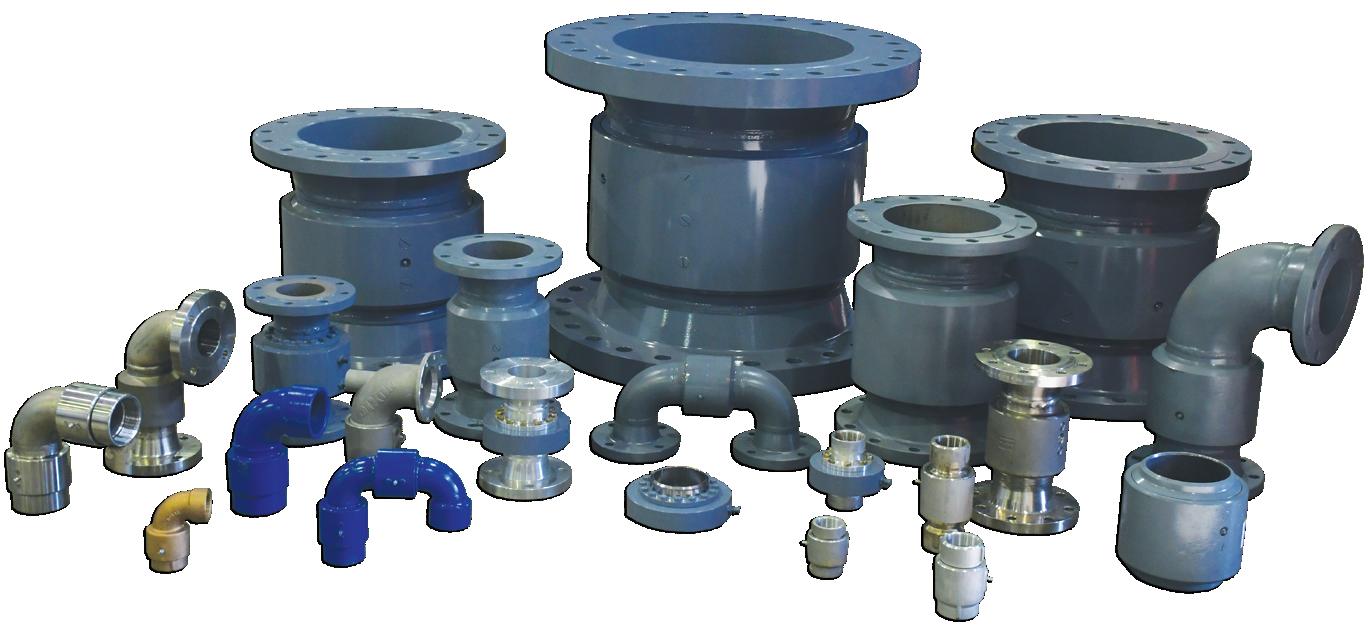
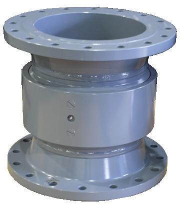
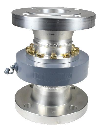
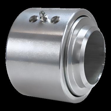
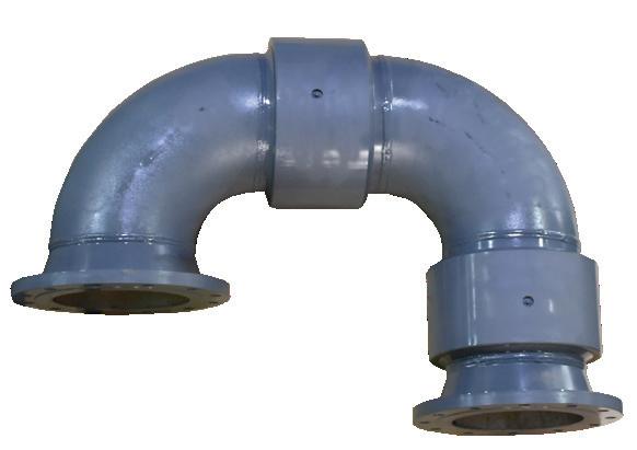
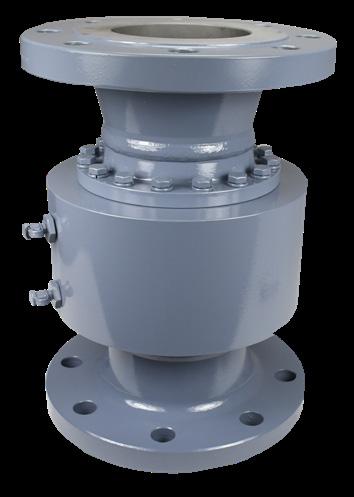
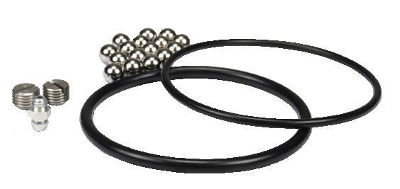
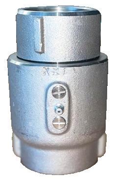
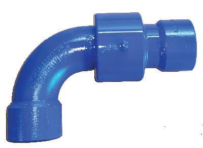
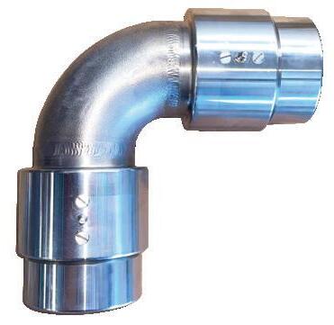
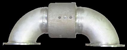
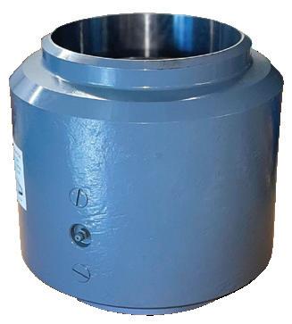
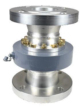
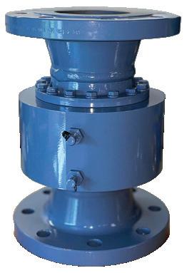
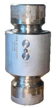
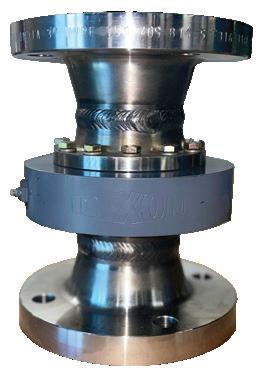
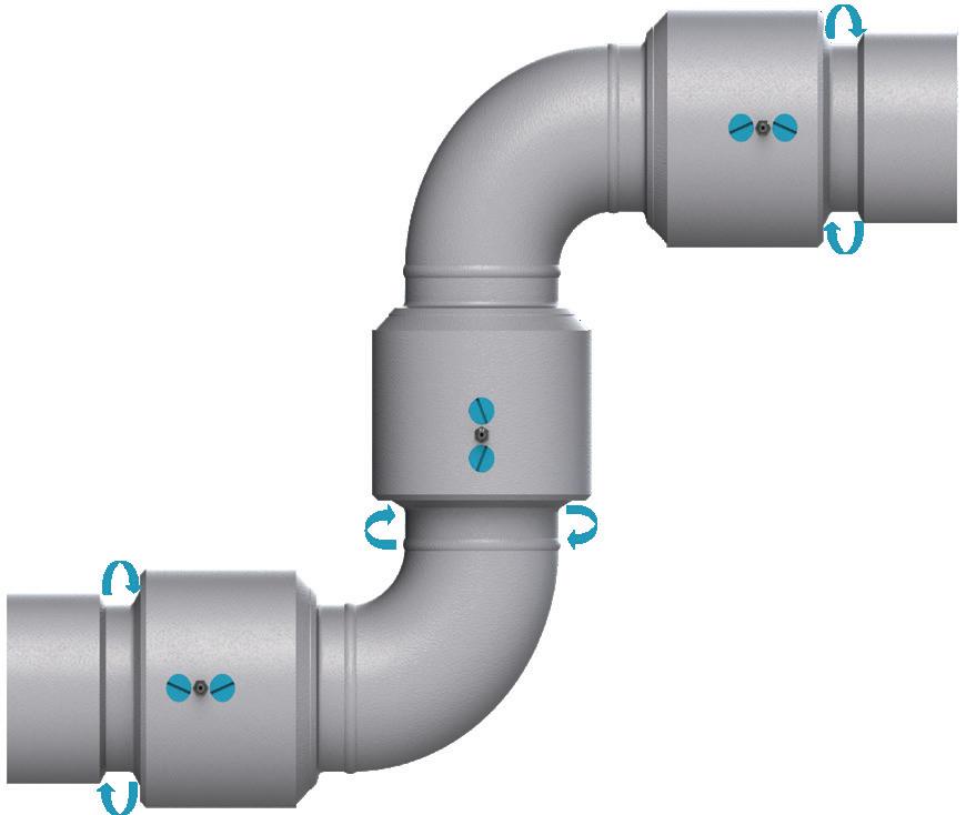
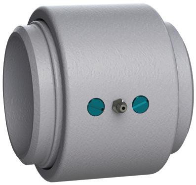
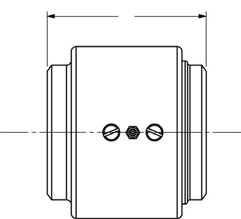
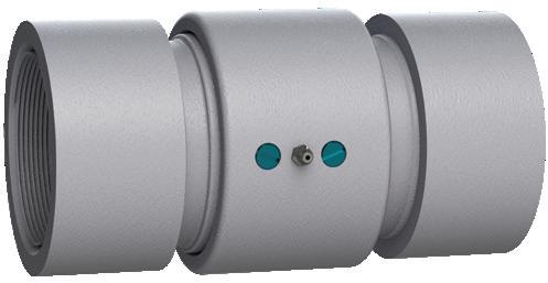
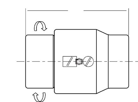
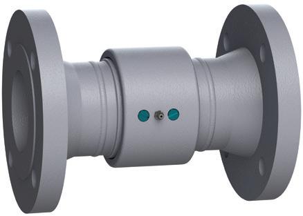
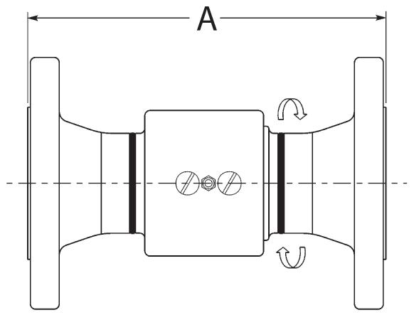
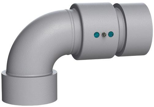
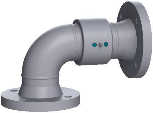
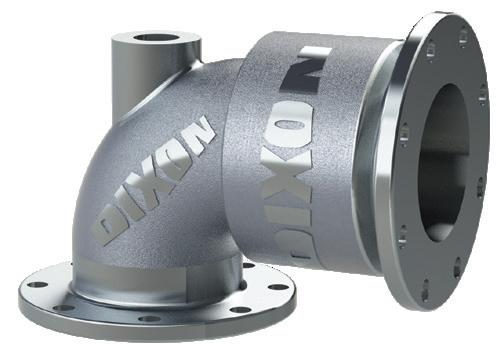
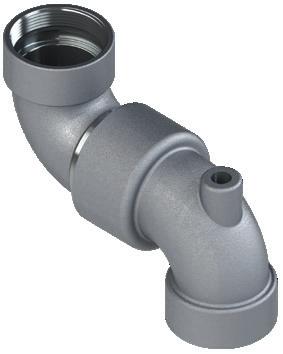
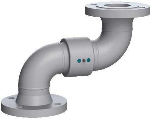
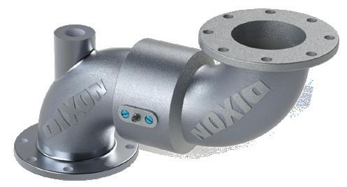
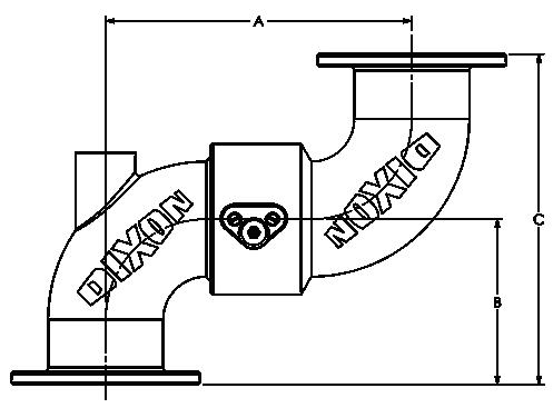
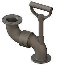
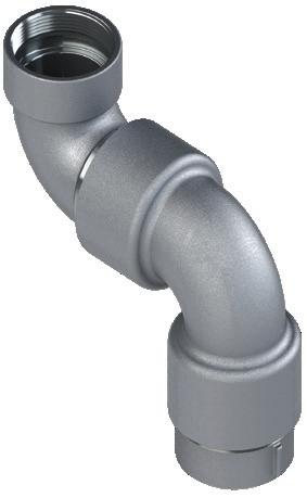
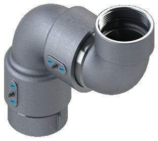
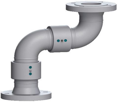
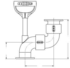
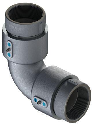
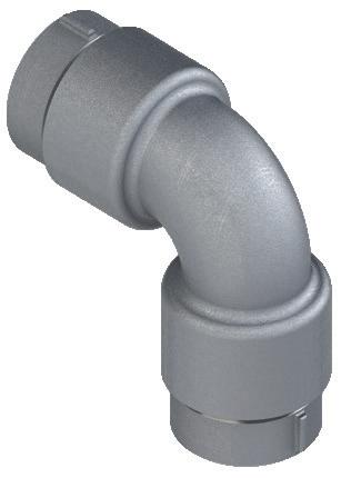
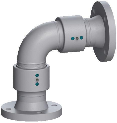
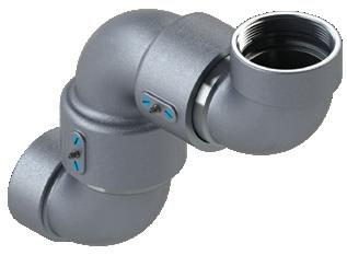
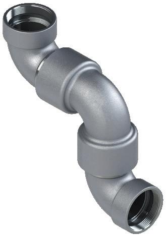
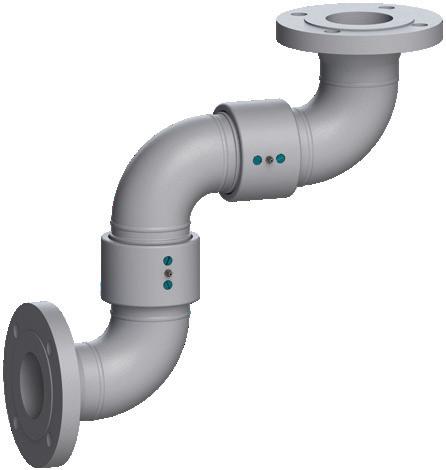
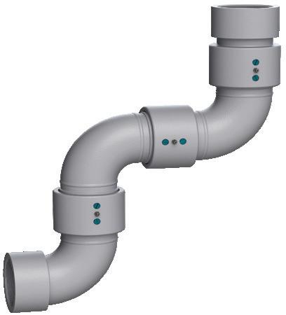
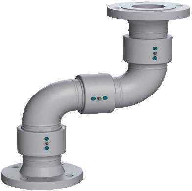
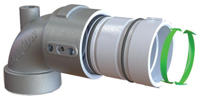
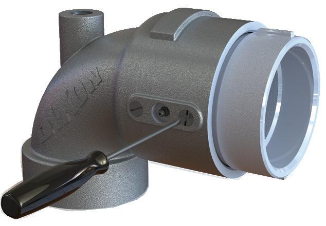
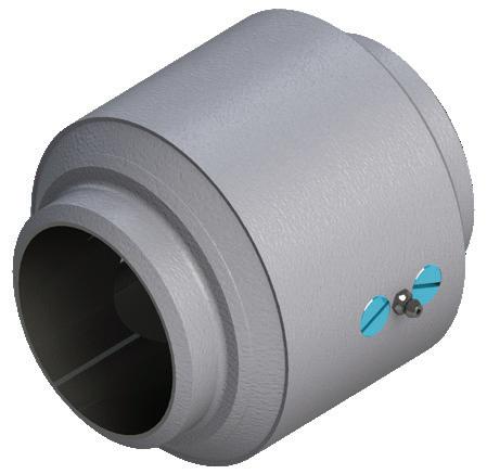
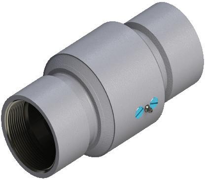
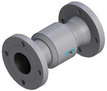
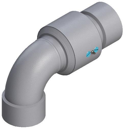
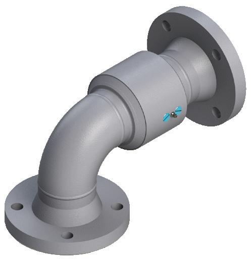
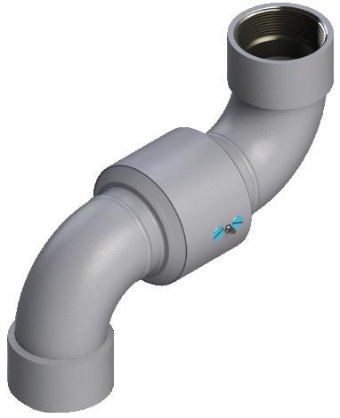
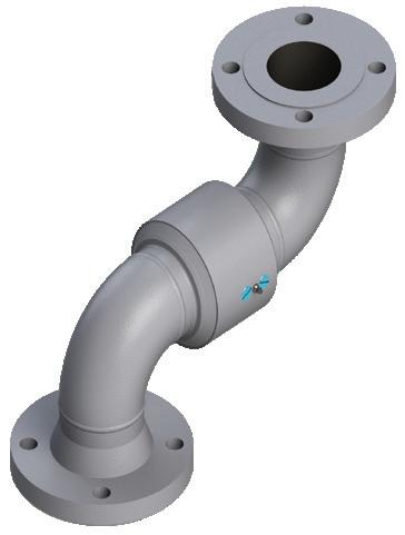
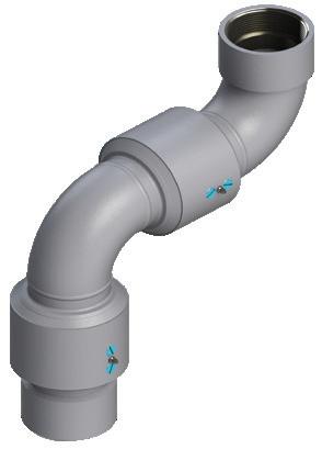
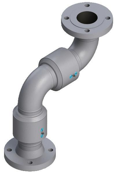
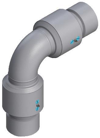
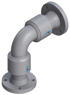
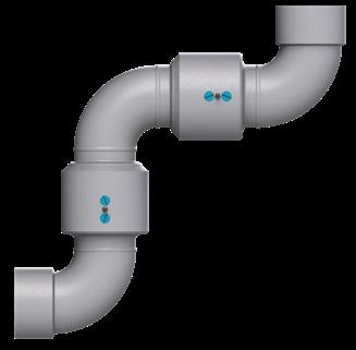
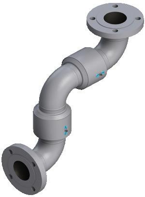
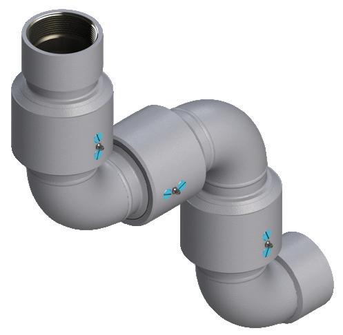
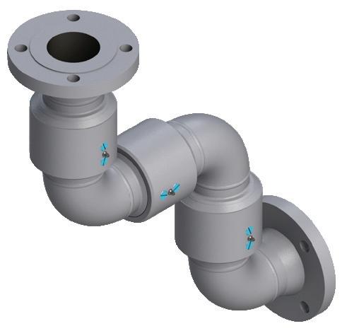
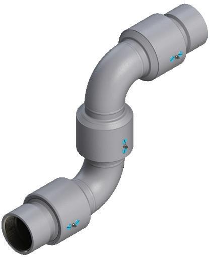
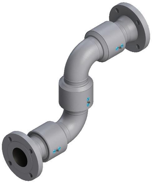
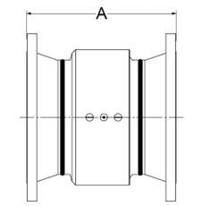
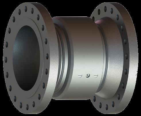
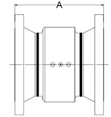
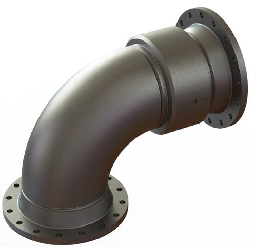
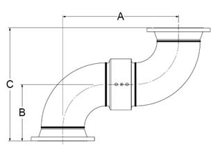
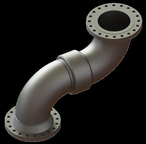
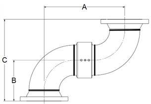
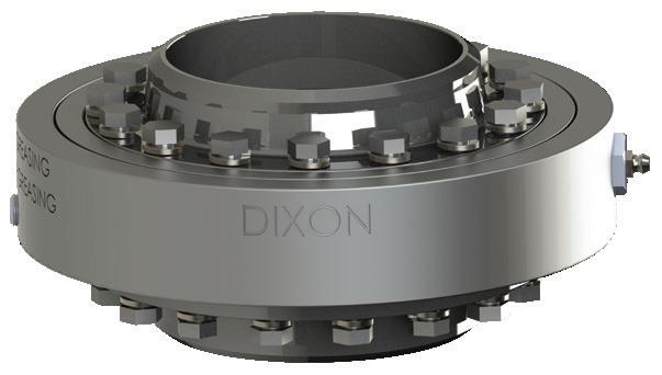
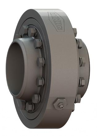
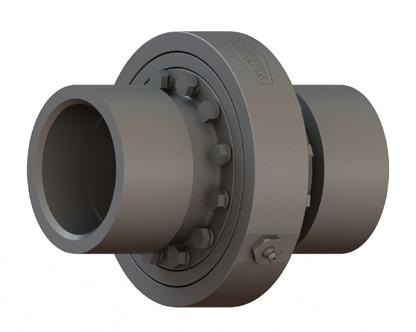
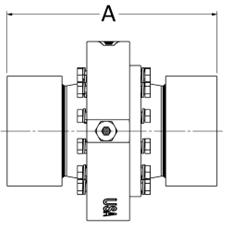
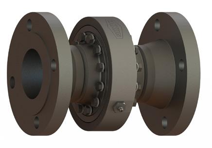
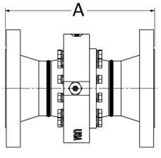
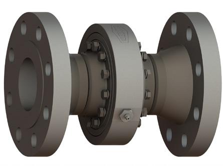
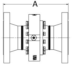
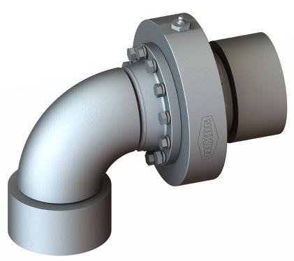
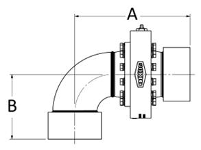
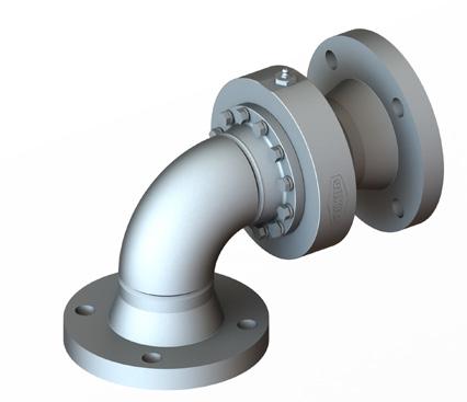
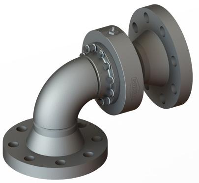
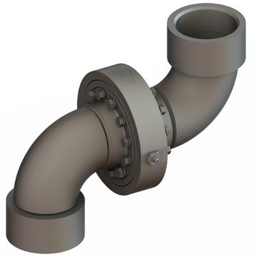
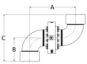
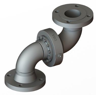
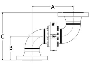
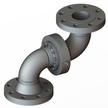
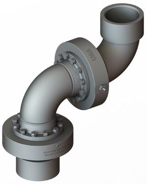
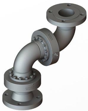
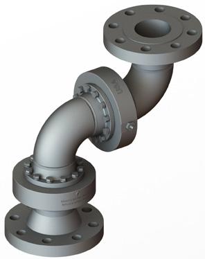
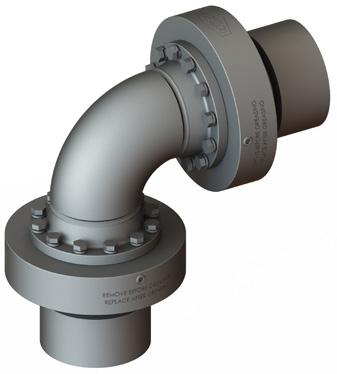
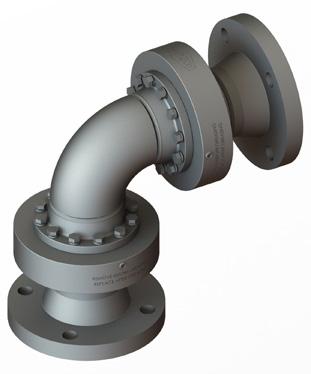
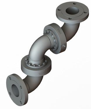
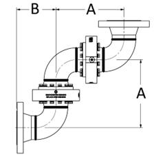
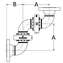
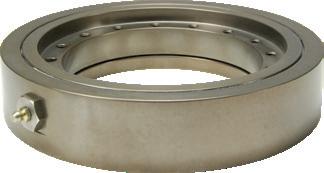
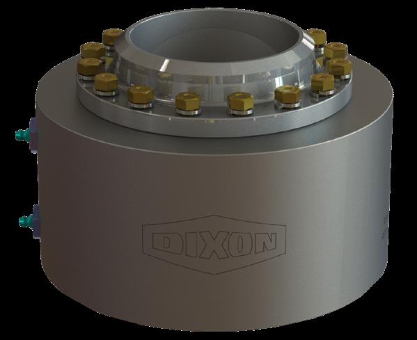
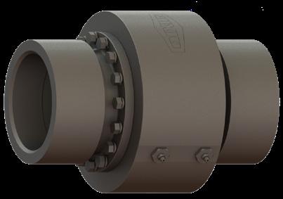
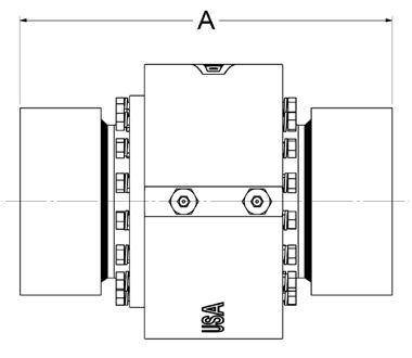
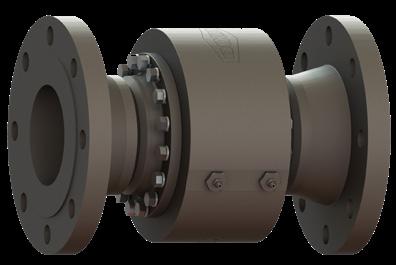
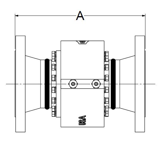
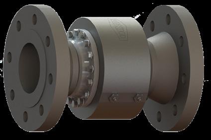
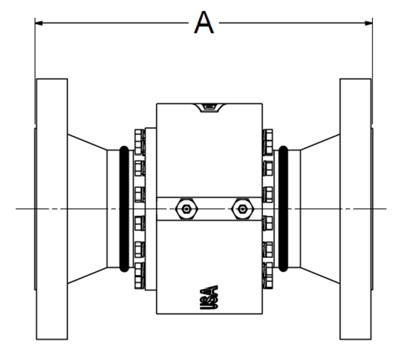
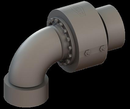
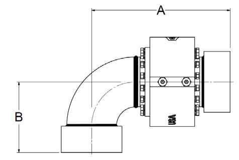
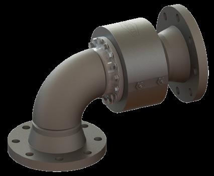
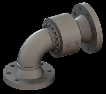
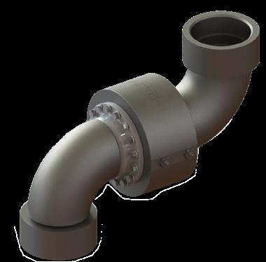
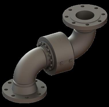
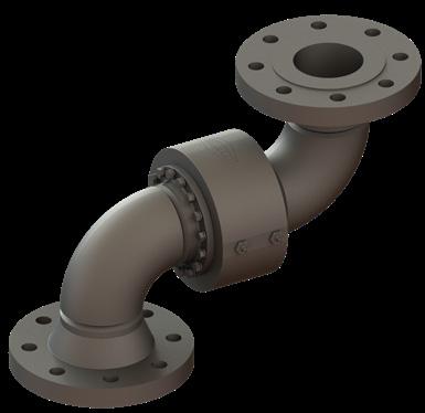
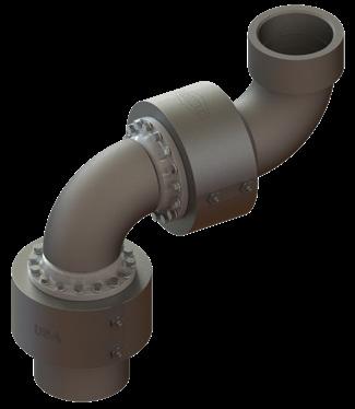
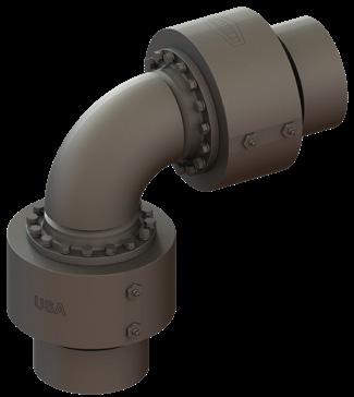
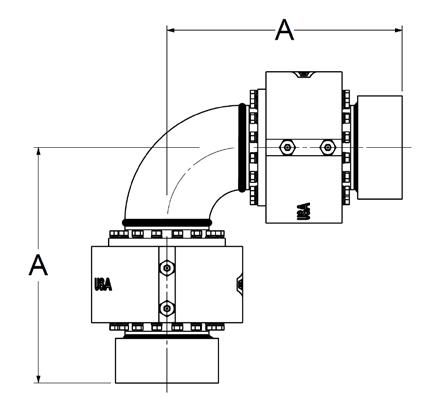
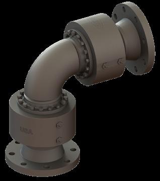
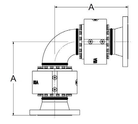
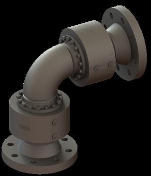
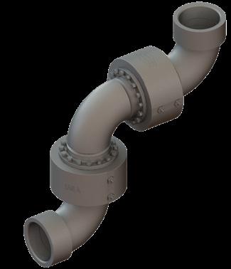
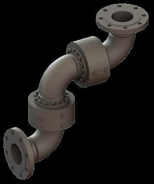
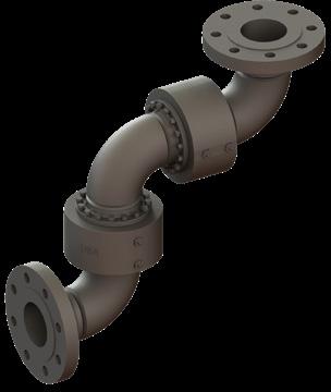
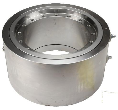
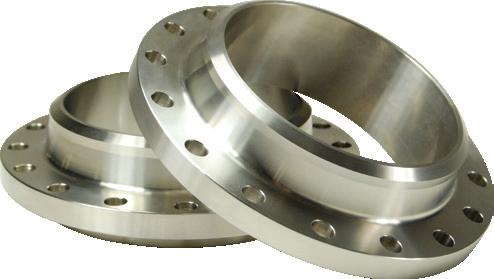
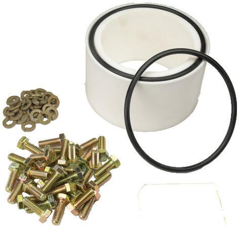
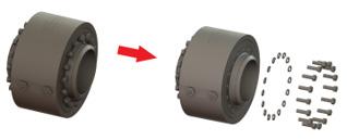
• Used wherever a leak-proof swivel connection is needed in pipelines or in combination with hoses to eliminate hose twisting.
• Ideal for a wide range of industries including petroleum, petrochemical, refining, mining, distilling, paint, farm irrigation and fertilizing, wastewater treatment plants, and food and beverage process equipment. Dixon® swivel joints are commonly used in blending plants, drum filling applications, fluid and dry bulk transfer, vacuum trucks, oil and gas trucks and water trucks. Larger swivels can be found in the steel industry, marine bulk transfer, and many more applications.
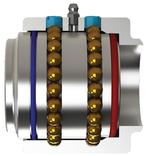
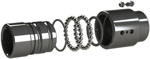
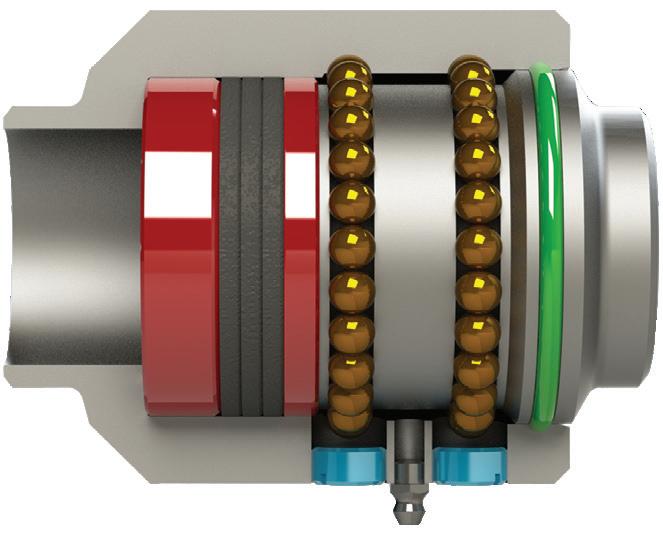
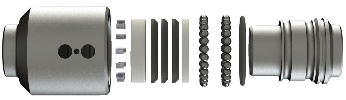
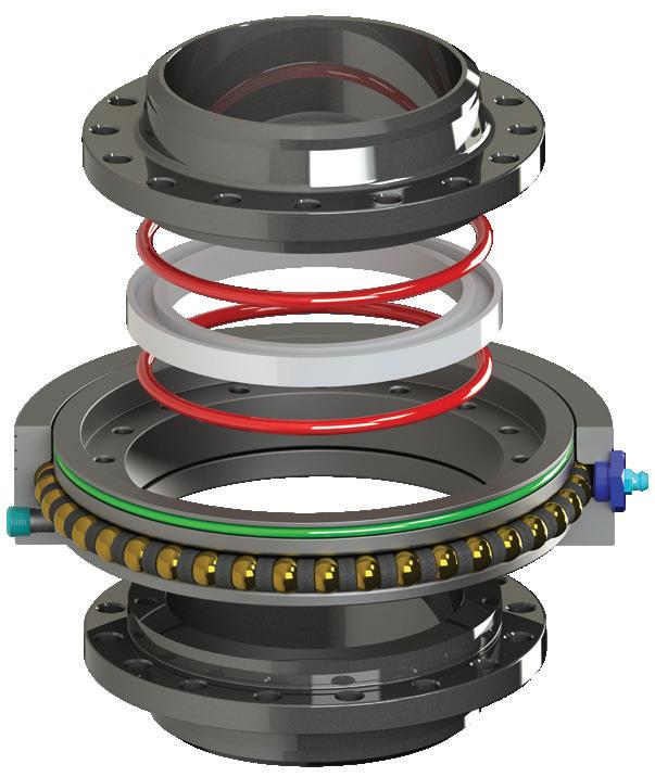
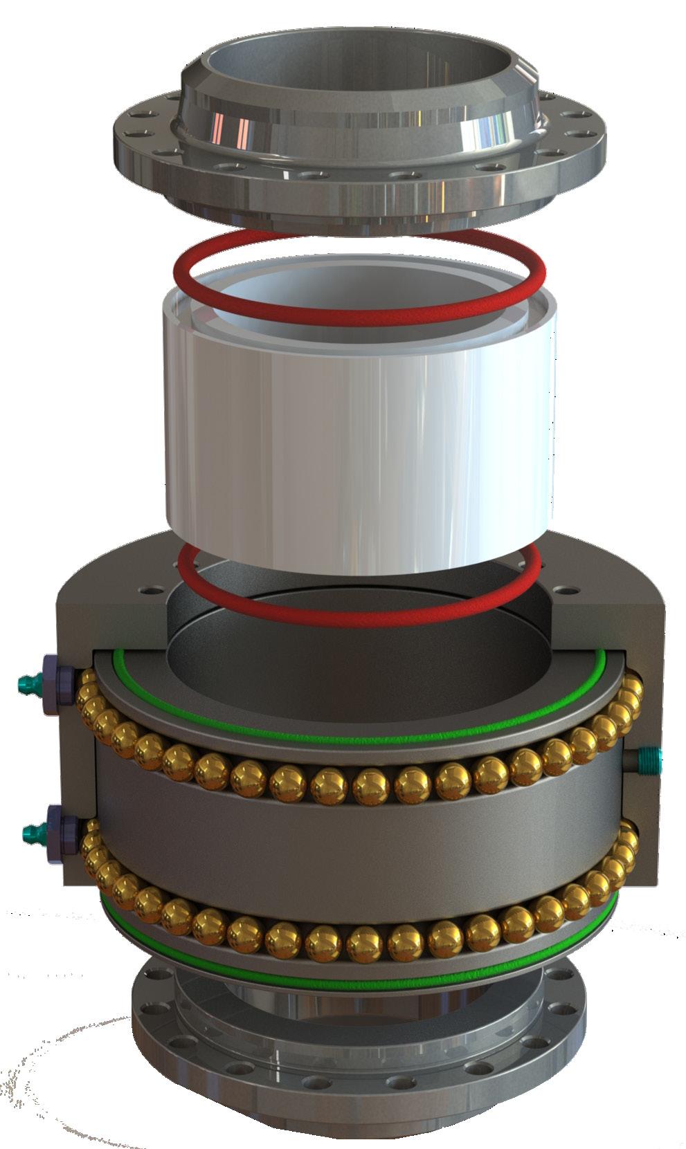
• Precision-machined design ensures alignment and years of trouble-free service
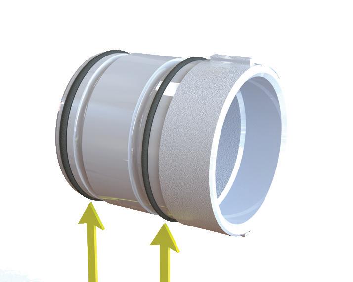
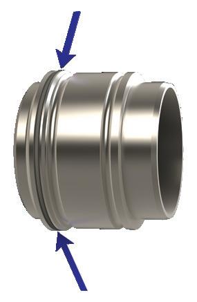
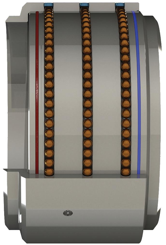
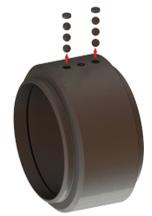
• O-ring dust seal protects the ball races and seals chamber from outside elements
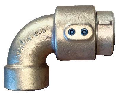
• Radius elbow design ensures a smooth flow path
• All swivels undergo rigorous hydrostatic testing prior to shipment to ensure performance and reliability, with the exception of weld end swivels, which are prepared for customer-specific testing after installation.
Additional Options
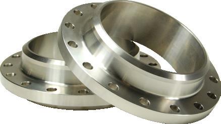
• End configurations: male NPT, female NPT, 150# flange, TTMA flange, grooved, weld end, and others upon request.
• Seal options: nitrile rubber, FKM, PTFE, EPDM, FDA nitrile rubber, and low temperature FKM
Dixon® swivels are recommended for use at the following maximum Non-Shock Cold Working Pressures (NSCWP) provided in PSI at ambient temperature 70°F (21°C) for 1" – 24" sizes:
• See pressure rating chart on pg. 70
• Vacuum/suction see pg. 70 for details
• When using flanged ends, the pressure rating will be reduced to coincide with that of the flange being used. Carbon steel and stainless steel 150# flanges are recommended for use at 275 PSI maximum and 300# flanges at 740 PSI at ambient temperature 70°F (21°C).
• TTMA flanges are recommended for use to 150 PSI maximum at ambient temperature 70°F (21°C)
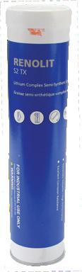
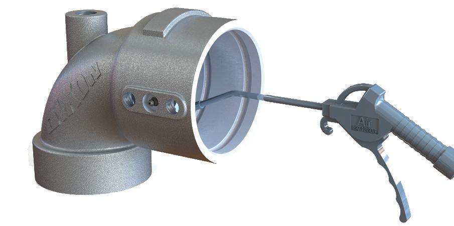
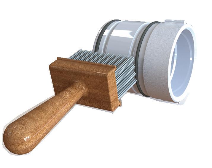
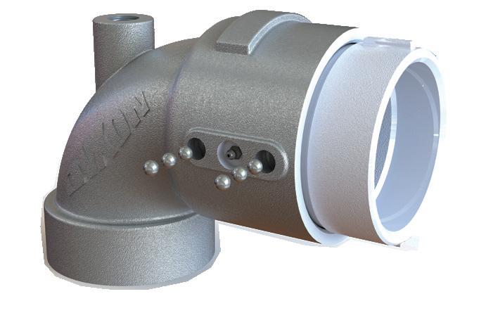
• Lubrication should be performed periodically, depending on service and operation conditions. Biannually is normally sufficient.
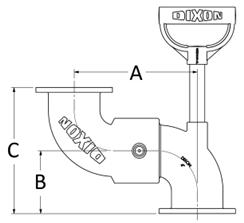
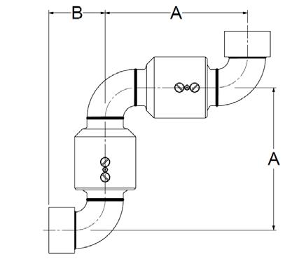
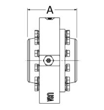
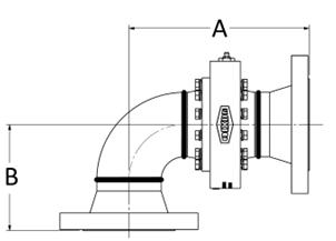
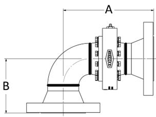
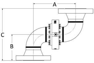
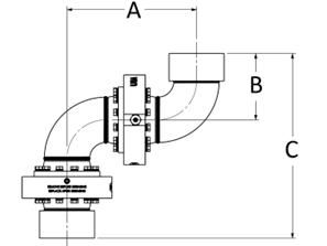
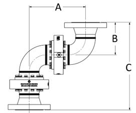
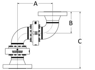
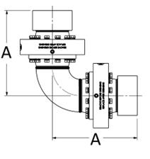
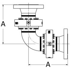
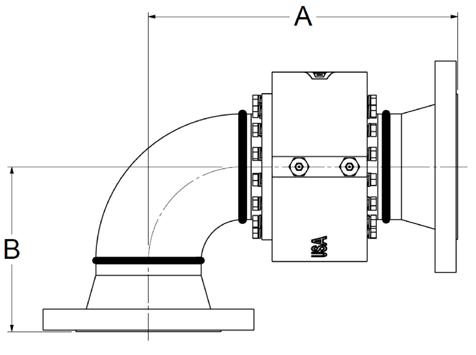
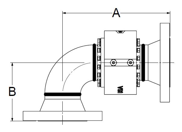
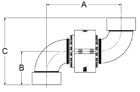
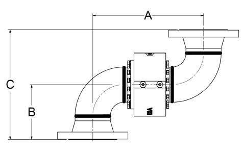
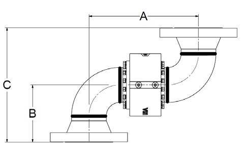
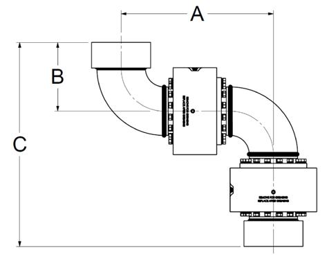
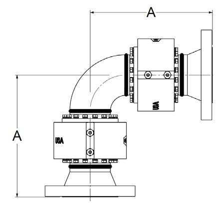
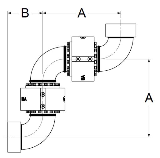
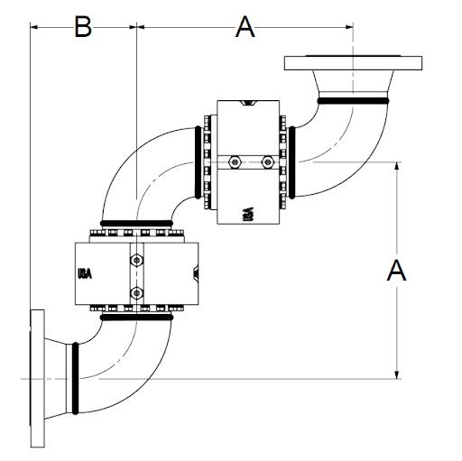
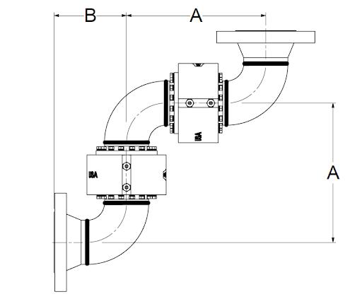
• All dimensions are approximate. Where critical, consult Dixon
Use with Hose
When using swivel joints to compensate for hose twist (e.g., Style 20 or Style 60), careful consideration is needed. The hose must be stiff enough to generate sufficient torque to activate the swivel before kinking occurs.
In many cases, lateral movement-induced twist can be resolved with a swivel joint (e.g., Style 40 or Style 30). If not, hose swivels may offer a solution. These non-ball bearing designs require less torque for rotation but are not intended for load-bearing applications.
It's important to note that some hoses, such as many metal hoses, may not produce enough torque to rotate even a hose swivel. On the other hand, stiffer hoses, like many armored hoses, can easily turn most swivels.
Pricing
Pricing is available upon request. Please contact Dixon for assistance with pricing and selecting the right equipment for your specific application.
Each swivel joint is custom-built to order, so returns are generally not accepted. However, return requests will be considered on a case-by-case basis. Approved returns will be subject to a restocking fee of 15%, along with any additional costs incurred.
S.T.A.M.P.E.D.
When fabricating and specifying assemblies ask the following questions:
Size: What is the I.D. (inside diameter)? What is the O.D. (outside diameter)? What is the overall length of the assembly required?
Temperature: What is the temperature range of the media (product) that is flowing through the assembly? What is the temperature range of the environment that surrounds the outside of the assembly?
Application: How is the assembly actually being used? Is it a pressure application? Is it a vacuum (suction) application? Is it a gravity flow application? Are there any special requirements that the assembly is expected to perform? Is the assembly being used in a horizontal or vertical position? Are there any pulsations or vibrations acting on the assembly?
Media: What is the media/material that is flowing through the assembly? Being specific is critical. Check for: Abrasive materials, chemical compatibility, etc.
Pressure: What is the maximum pressure including surges (or, maximum vacuum) that this assembly will be subjected to? Always rate the maximum working pressure of your assembly by the lowest rated component in the system.
Ends: What end connection has been requested by the user? Are they the proper fittings for the application?
Dixon: Be Safe: Any questions on application, use, or assembly, call 877.963.4966.
Color Identification
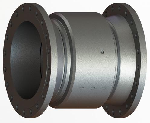
Color identification is important in manufacturing processes because it aids in quickly distinguishing differences between parts, materials, and assembly stages, thereby reducing errors and improving efficiency. At times color identification can also clarify the type of media that is flowing through a piping system. However, for the standard Dixon Swivel Joints the color or finish aids in identifying the material and seal design.
Part Number Etching Identification
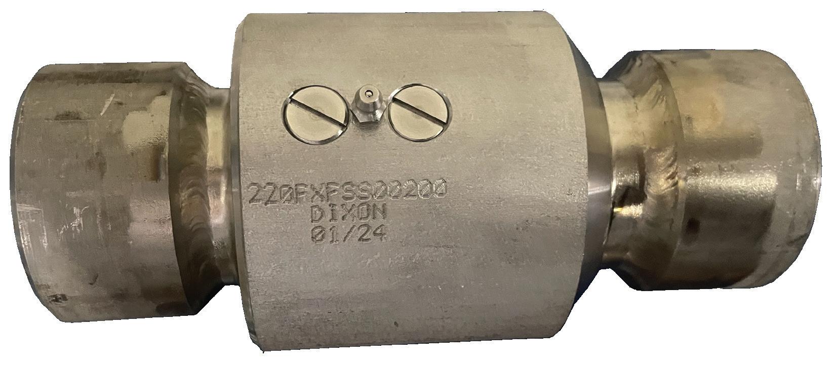
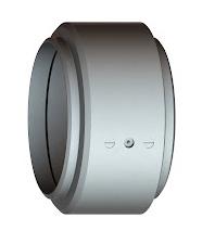
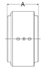
Dixon Swivel Joints are etched with their unique part number for accurate identification. This practice supports quality control and inventory management. Additionally, the etched identification helps simplify maintenance and replacement, as it allows quick reference to specific parts in technical documentation and service records.
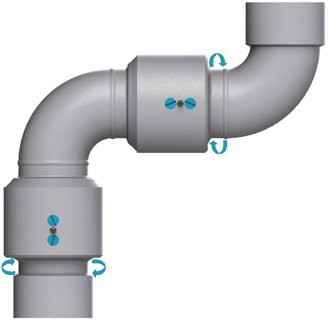
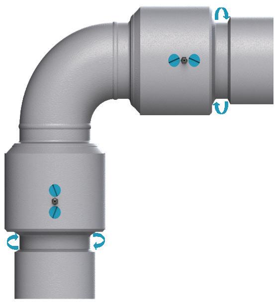
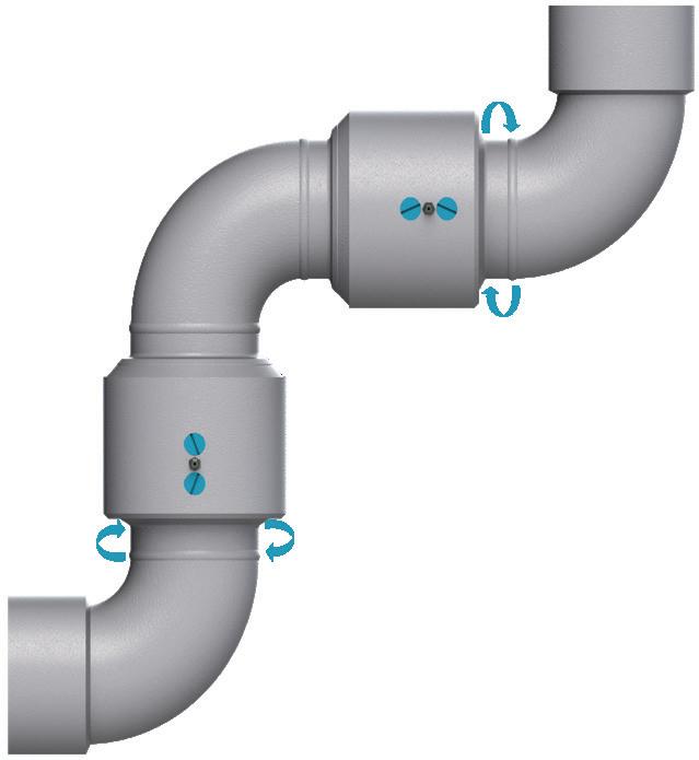
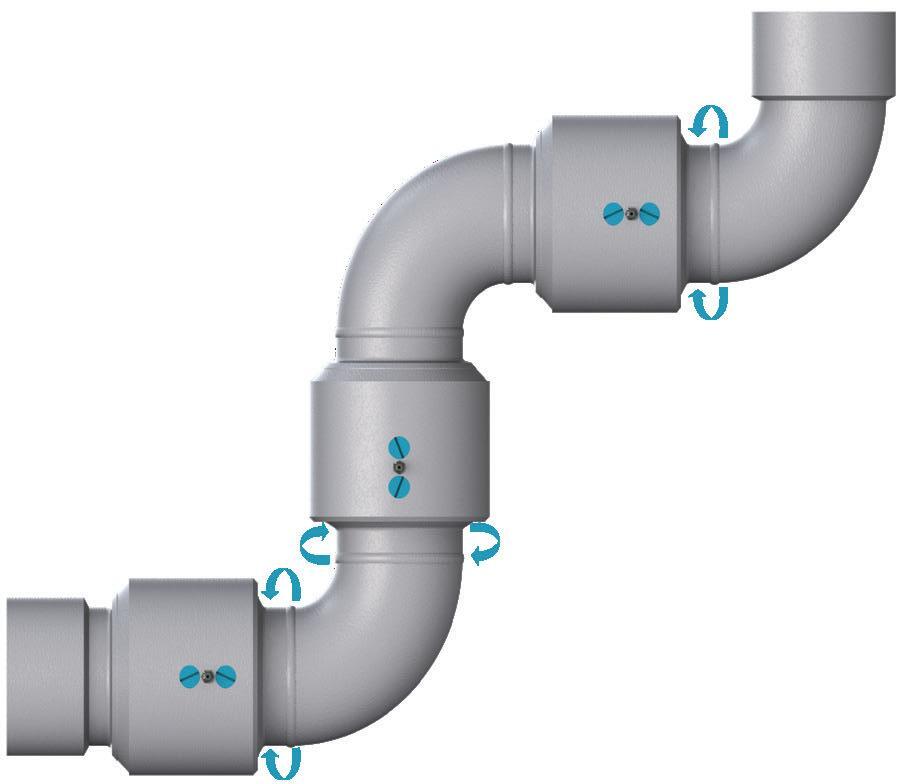
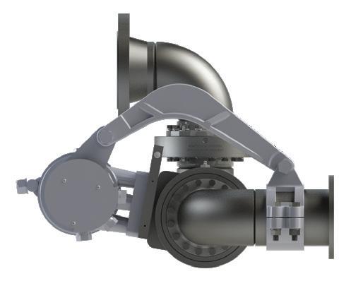
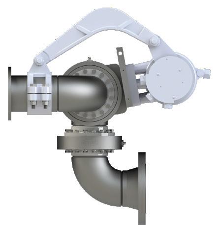
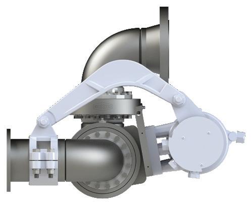
Swivel Joint Styles
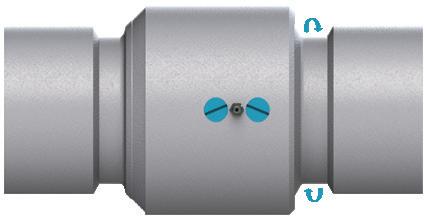
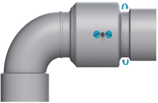
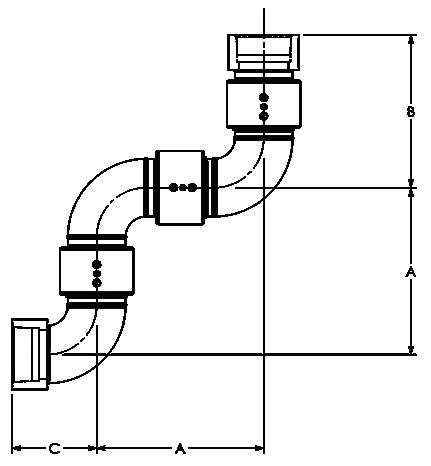
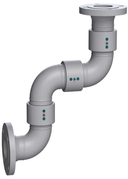
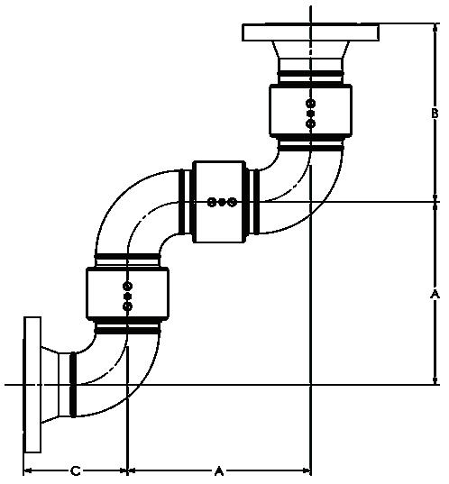
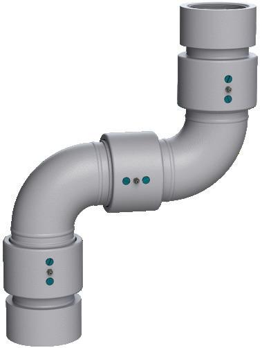
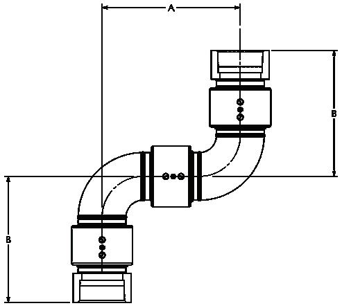
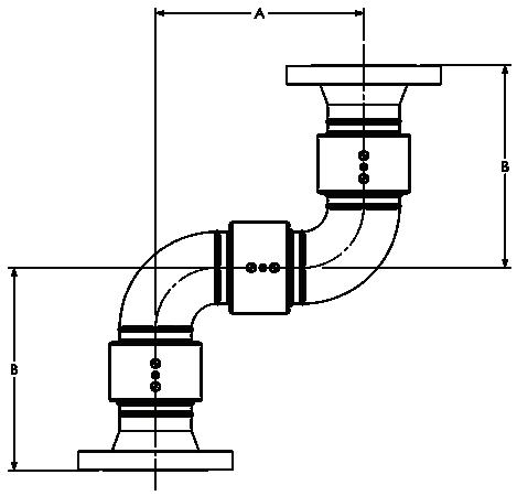
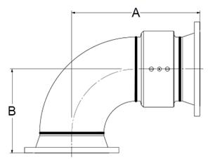
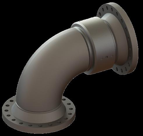
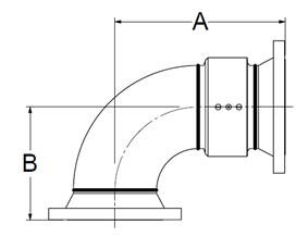
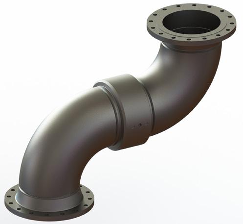
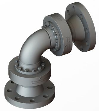
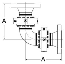
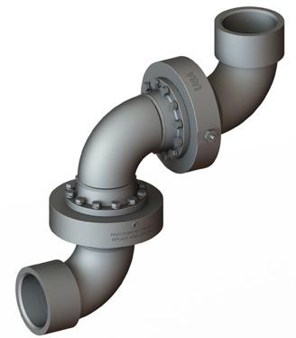
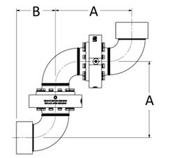
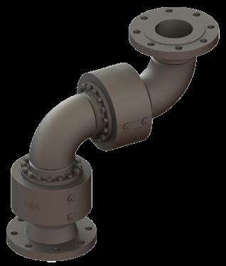
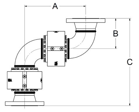
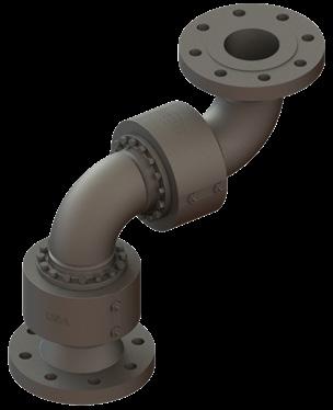
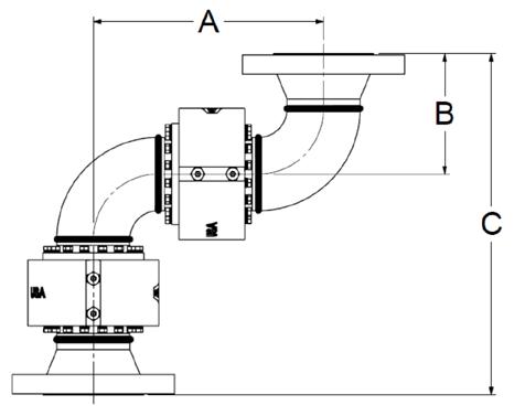
Double Plane
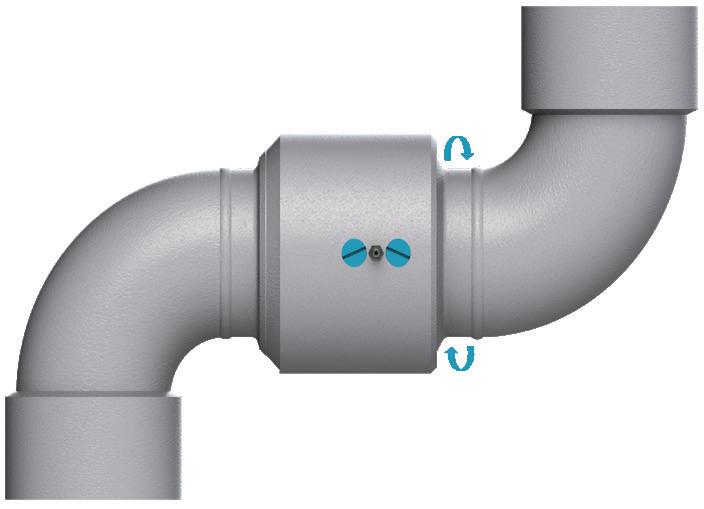
Triple Plane
Single Plane
O-Ring Swivel Joints
O-Ring Swivel Joints
Applications
• Commonly used in tote/drum loading, loading arms, hose and steam, water supply lines, tank trucks, compressed air, asphalt, irrigation, suction and vacuum, petroleum, and mining.
Sizes
• 1" - 4"
Features
• O-ring pressure seal ensures a leak-proof seal and smooth rotation with lower torque
• Smooth moving seal for high-volume drum and tote loading
• Available working pressure ratings up to 1,000 PSI, based on material and end connections
• Available end connections include: 150 Ibs. and 300 Ibs. flanges, FNPT, MNPT, butt weld, TTMA, and others upon request
• End connections and materials offered may vary based on size, contact Dixon® for details
Materials
• Available materials include carbon steel, 316L stainless steel, aluminum, brass, and ductile iron
Bill of Materials
1. Body
2. Sleeve
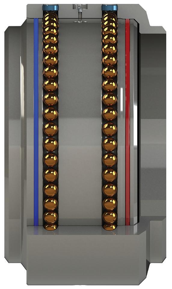
3. Ball bearings
4. Grease fitting
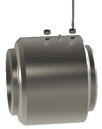
5. Ball retainer screws
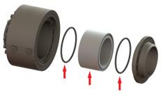
6. O-ring (dust seal)
7. O-ring (pressure seal)
O-Ring Swivel Joint Numbering System
2 20 F x F OC 0
1 = 1" 20 F (FNPT) x F (FNPT) AL = aluminum
125 = 1-1/4" 30 W (weld) x W (weld) BR = brass 1 = FKM
150 = 1-1/2" 40 FG (150#) x FG (150#) MI = ductile iron 2 = PTFE
250 = 2-1/2" 60 TF (TTMA) x TF (TTMA) OS = O-ring 316 stainless steel 4 = FDA nitrile rubber 4 = FDA nitrile rubber 4 = low temperature 3 = 3" 70 BP (BSPP) x BP (BSPP)
=
4 = 4" 80 BT (BSPT) x BT (BSPT)
10 G (groove) x G (groove) M (MNPT) x M (MNPT)
*If ordering a handle, the zero would be replaced by H or B. Use "H" for a heavy-duty D-style shovel handle.
NOTE: Other end connections or seals are available upon request.
• Brass O-ring: 1-1/2" - 3"
• Ductile iron O-ring: 1-1/2" - 4"
• Standard grease fitting without ball check on all O-ring Swivel Joint materials except 316 stainless steel. Ask for check ball if required. 316 SS O-ring Swivel Joints include SS grease fitting with ball check.
• Dixon® does not offer 4" O-ring configuration for stainless steel material.
O-Ring Swivel Joints
O-Ring Style 20 - Weld x Weld
O-Ring Style 20 - FNPT x FNPT
O-Ring Style 20 - 150# Flange x 150# Flange
O-Ring Style 30 - FNPT x FNPT
O-Ring Style 30 - 150# Flange x 150# Flange
O-Ring Style 30 - TTMA Flange x TTMA Flange
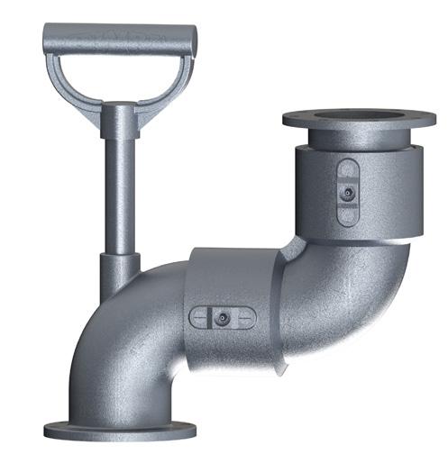
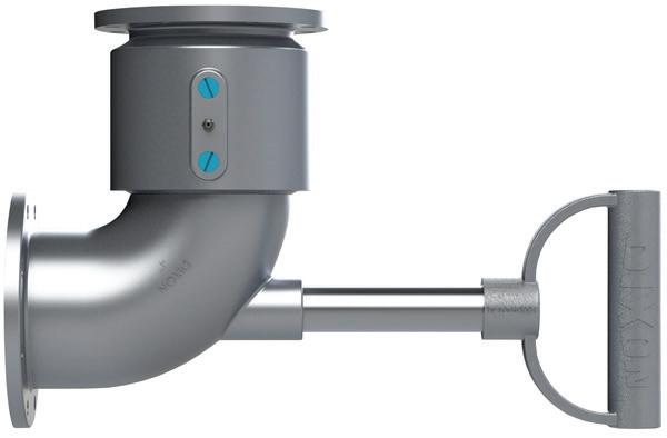
O-Ring Style 30 - TTMA Flange x TTMA Flange with D-Handle
O-Ring Style 40 - FNPT x FNPT
O-Ring Style 40 - 150# Flange x 150# Flange
O-Ring Style 40 - TTMA Flange x TTMA Flange
O-Ring Style 40 - TTMA Flange x TTMA Flange with D-handle
O-Ring Style 50 - FNPT x FNPT
O-Ring Style 50 - 150# Flange x 150# Flange
O-Ring Style 50 - TTMA Flange x TTMA Flange
O-Ring Style 50 - TTMA Flange x TTMA Flange with D-handle
*If the part number does not include characters for the dust seal, the kit will include a nitrile rubber dust seal.
Replacement Ball Bearings for O-Ring Swivels
O-Ring Swivel Seal Replacement Procedure
NOTE: Instructions are not for assembly with spring-loaded PTFE pressure seal, consult Dixon®
1
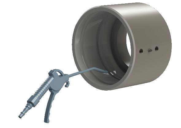
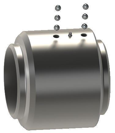
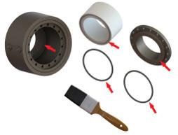
Remove the ball retainer screws. Add a sufficient amount of solvent into each raceway to flush out the lubricant. Rotate the sleeve, catching the balls as they fall out. When all the balls have been removed, the body and sleeve can be separated. Discard old seals. Thoroughly clean the body and sleeve.
2
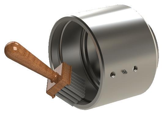
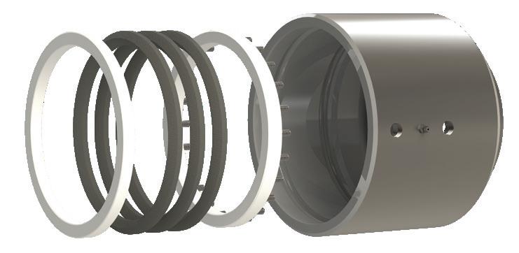
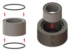
Install the new O-rings on the sleeve, dust seal to the rear, product (pressure) seal up front.
3
Lubricate the body and the sleeve with grease.
4
Insert the sleeve into the body, slowly rotate the sleeve while inserting into the body.
5When the sleeve is fully inserted, feed the ball bearings into the raceways while rotating the sleeve. To make space for all the balls, insert a screw driver into the raceway, while continuing to rotate the sleeve in one direction (be careful not to damage the threads). This will cause the balls to jam up, making room for the remaining balls. Now reverse rotation of sleeve and insert the remaining balls.
6
Reinstall ball retainer screws until tight. If this interferes with the smooth rotation of the ball bearings, then back off 1/8 to 1/4 turn. A thread locking sealant is recommended to prevent screws from backing off. After pressure testing, the unit is ready for installation.
Body and sleeve are matched during manufacturing. Do
V-Ring Swivel Joints
V-Ring Swivel Joints
Applications
• Commonly used in the steel industry, marine bulk transfer, waste water treatment plants, and petrochemical industry.
Sizes
• 2" - 14"
Features
• V-ring, also known as chevron packing, is a multiple lip seal known for its reliability and long life.
• The three V-ring seals are designed to seal even under misalignment caused by race wear from years of service. This design results in longer time between service periods, increased up-time efficiencies, and lower maintenance costs.
• Spring-loaded triple V-ring sealing system ensures a leak-proof seal at high or low pressure and extends seal life
• Swivels are shipped standard with the following:
• Nitrile rubber pressure seals and dust seals
• Carbon steel ball bearings
• PTFE retainers
• Available working pressure ratings up to 1,000 PSI
• End connections and materials offered may vary based on size, contact Dixon® for details
Materials
• Available materials include carbon steel, 316L stainless steel, and aluminum
Bill of Materials
1. Body
2. Sleeve
3. Ball bearings
4. Grease fitting
5. Ball retainer screws
6. O-ring (dust seal)
7. V-ring (pressure seal)
8. Seal retainer
9. Spring retainer
10. Springs
V-Ring Swivel Joint Numbering System
8 = 8"
= 10"
12 = 12"
14 = 14" 10 G (groove) x G (groove) M (MNPT) x M (MNPT)
NOTE: Other end connections or seals are available upon request.
• Standard grease fitting without ball check. Ask for ball check if required.
• Aluminum V-ring version only available in 6" and 8"
• 3 V-ring (pressure seal) in the material indicated
• 1 dust seal in the material indicated
• 2 ball retainer screws
• Number of grease plugs varies depending on size
• 2 PTFE retainers
NOTE: All rebuild kits are per plane of rotation Different grade of ball bearing materials available upon request Total Rebuild Kit V-Ring Pressure Seal Material Size
3 T RK V TF VI
• Number of ball bearings varies depending on size NOTE: All rebuild kits are per plane of rotation Different grade of ball bearing materials available upon request Size
*If the part number does not include characters for the dust seal, the kit will include a nitrile rubber dust seal.
Remove the ball retainer screws. Add a sufficient amount of solvent into each raceway to flush out the lubricant. Rotate the sleeve, catching the balls as they fall out. When all the balls have been removed, the body and sleeve can be separated. Discard old seals. Thoroughly clean the body, sleeve retainer, spring retainer, and springs.
2
Lubricate the body unit with a Moly lubricant or equivalent.
3
Place the assembled spring retainer unit (spring end first) into the body*. Place the set of V-rings onto the spring retainer. Be sure V-rings are installed with the sealing lips facing toward the retainer. Lubricate the body and seals with a moly lubricant or equivalent.
4
Set the dust seal into O-ring groove on the sleeve. Place the seal retainer on the sleeve with the grooved end facing the V-rings. Lubricate the sleeve with grease.
5
Insert sleeve into body, compressing swivel joint together until ball races or body and sleeve are in alignment (do not rotate either unit while compressing). Care should be taken to avoid pinching or scoring of V-rings. Drop balls into raceway holes, rotating the sleeve slowly as you load. To make space for all the balls, insert a screw driver into the raceway while continuing to rotate the sleeve in one direction (be careful not to damage the threads). This will cause the balls to jam up, making room for the remaining balls. Now reverse the rotation of the sleeve and insert the remaining balls.
6
Reinstall ball retainer screws until tight. If this interferes with the smooth rotation of the ball bearings, then back off 1/8 to 1/4 turn. A thread locking sealant is recommended to prevent screws from backing off. After pressure testing, the unit is ready for installation.
* The last coil of the springs has been upset (O.D. slightly larger). When upset end is inserted into the holes provided in the spring retainer, the springs remain secure.
Body and sleeve are matched during manufacturing. Do not mix components with other units.
Cap Seal Swivel Joints
Cap Seal Swivel Joints
Applications
• Liquid media transfer lines in steel-making plants, floating roof drains, and floating suction systems
Sizes
• 14” – 24”
Features
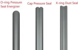
• Pressure seal consists of a nitrile or FKM energizer with glass Moly filled PTFE outer cap seal allowing for a lower torque requirement to rotate
• Nitrile or FKM X-ring dust seal for additional reduction in required torque to rotate
• Triple ball-race design for 18” and larger
• Hardened ball races for increased load capacities of carbon steel swivels
• Available end connections include 150# and 300# flanges and weld ends. Contact Dixon® for more details
NOTE: Other end connections or seals are available upon request.
• Includes standard issue grease fittings without ball check. Ask for ball check if required.
Cap Seal Style 20 - Weld x Weld
Cap Seal Style 20 - 150# Flange x 150# Flange
Cap Seal Style 20 - 300# Flange x 300# Flange
Cap Seal Style 30 - 150# Flange x 150# Flange
Cap Seal Style 30 - 300# Flange x 300# Flange
Cap
Cap Seal Style 40 - 150# Flange x 150# Flange
Cap Seal Style 40 - 300# Flange x 300# Flange
Cap Seal Swivel Joint Seal Replacement Procedure
1 Remove the raceway set screws. Rotate the sleeve inside the body, while removing the ball bearings using a magnetic pick-up tool. When all the balls have been removed, the body and sleeve can be separated.
2 Remove the seals using hand tools that will not damage or scratch the seal grooves. Discard old seals. Thoroughly clean the body, sleeve, and ball bearings using solvent/degreaser.
3 Apply grease to the dust seal groove, which is the one closest to the weld, using a small chip/paint brush.
4 Dry wipe the X-ring (quad) dust seal using a shop towel to remove any debris (refer to seal guide). Put the dust seal into the dust seal groove of the swivel sleeve. Inspect the dust seal to make sure there are no twists.
5 Apply grease to the dust seal and the outside of the swivel sleeve on all surfaces extending from the dust seal groove to the pressure seal groove.
6 Install the O-ring energizer into the pressure seal groove (Refer to Seal Guide). Inspect the O-ring energizer to make sure it is not twisted and apply grease to the O-ring energizer.
Cap
Cap Seal Swivel Joint Seal Replacement Procedure
7 Install the cap pressure seal over top of the pressure seal energizer (Refer to seal guide). The small groove faces outward. Metal or sharp tools must not be used to install the cap seal. Apply grease to the cap pressure seal.
8 Apply grease to the inside of the swivel body on all surfaces extending from the dust seal sealing face to the pressure seal sealing face.
9 Move the swivel sleeve (or move the swivel body) so that the sleeve and body are concentrically aligned.
10 Insert the swivel sleeve into the body until the raceways are aligned.
11 Insert the ball bearings into the raceways while rotating one of the components (body or sleeve).
12 Install the set screws and grease plugs. Add grease into the grease plug, as necessary (application dependent).
Split Flange Swivel Joints
Split Flange Swivel Joints
Applications
Seal pack: pressure seal O-rings (2) and PTFE retainer
Grease inspection port
O-ring dust seals (2) (Inner dust seal not shown) Ball bearings and spacers
piece (2)
Grease fitting / bearing port
• For use in industries from petroleum, blending plants, petrochemical, refining, mining, distilling, paint plants, farm irrigation and fertilizing, wastewater treatment, food and beverage process equipment, marine, and many more
Sizes
• 2", 3", and 4"
Features
• Bearing pack design allows easy seal change without removing the ball bearings
• Simple maintenance: remove one nose piece, replace seal pack, and reinstall with little downtime
• In-stream seal separates the wetted area from the ball bearings, allowing for longer bearing pack life compared to conventional swivels
• Single wide-set bearing race for higher moment loads
• Compact design for low-profile applications
• Full penetration weld
Materials
• Bearing pack: through hardened forged high-carbon alloy
• 4" are available with a optional aluminum bearing back in materials
• Material contact surfaces: stainless steel, carbon steel, or aluminum nose pieces
• Seals: Baylast™, FKM, PTFE, and more upon request
Specifications
• Pressure rating: up to 600 PSI
• Standard temperature range with Baylast™ seals is -30°F to 212°F (-34°C to 100°C); contact factory for other temperature requirements
Available options
• Swivel end configurations: 150 Ibs. and 300 Ibs. flanges, FNPT, MNPT, butt weld, TTMA, and others upon request
Split Flange Swivel Joint Numbering System
Nose
Split Flange Style 20 - Weld x Weld
Split Flange Style - 20 FNPT x FNPT
Split Flange Style 20 - 150# Flange x 150# Flange
Split Flange Style 20 - 300# Flange x 300# Flange
Split Flange Style 30 - FNPT x FNPT
Split Flange Style 30 - 150# Flange x 150# Flange
Split Flange Style 30 - 300# Flange x 300# Flange
Split Flange Style 40 - FNPT x FNPT
Split
Flange Style 40 - 150# Flange x 150# Flange
Split Flange Style 40 - 300# Flange x 300# Flange
- carbon steel 81
- stainless steel 80
- aluminum 37
Split Flange Style 50 - FNPT x FNPT
Split Flange Style 50 - 150# Flange x 150# Flange
Split Flange Style 50 - 300# Flange x 300# Flange
Split
Part
Split Flange Style 60 - FNPT x FNPT
Split Flange Style 60 - 150# Flange x 150# Flange
Split Flange Style 60 - 300# Flange x 300# Flange
Split Flange Style 70 - FNPT x FNPT
Split Flange Style 70 - 150# Flange x 150# Flange
Split Flange Style 70 - 300# Flange x 300# Flange
Split Flange Swivel Joints
Split Flange Swivel Components
Bearing Packs
Feature
• Single wide-set bearing race for high moment loads
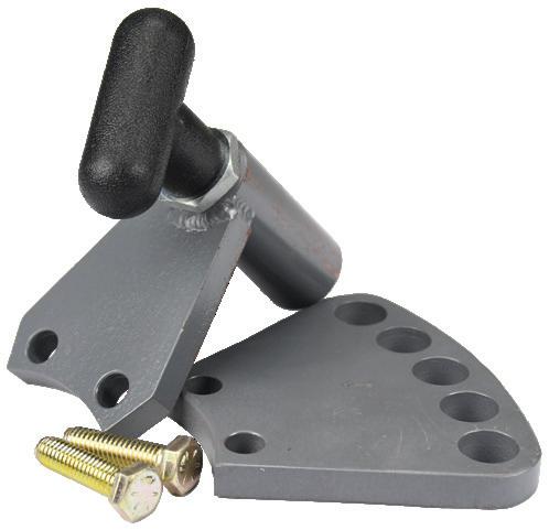
locking single hole T-handle kit for split flange swivel joints
locking multiple hole T-handle kit for split flange swivel joints
LA-SFLOCKTHK-S
LA-SFLOCKTHK-M
Warning: This item is only intended to restrain the rotation during storage and is limited to a maximum of 12 in-lbs. of torque.
Split Flange Swivel Joints
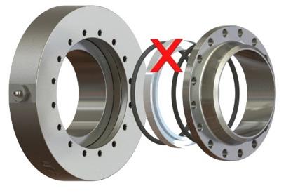
Split Flange Swivel Joint Seal Replacement Procedure
To change the seals in a Dixon® split flange swivel joint you will need the following items:
• 1/2” wrench or socket wrench with 1/2” sockets
• Torque wrench
• Application-appropriate grease
• Repair kit
1
Follow your company guidelines to properly shut down the system and confirm there is no residual pressure in the line. Support or remove any components necessary to disconnect at least one nose piece.
2
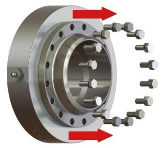
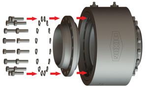
Remove all the bolts and washers from one of the nose pieces. Pick the side that gives the best access to the seal gland.
3a
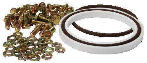
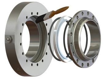
Remove and discard the old O-rings and PTFE H-ring. Clean the seal gland area.
3b
Lubricate the body and sleeve, new H-ring, and O-rings with grease.
4
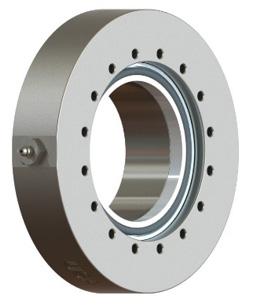
Install the replacement O-rings and the new H-ring. Make sure the O-rings are set in on each side of the H-ring. Be careful not to pinch the O-rings during reassembly.
5
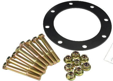
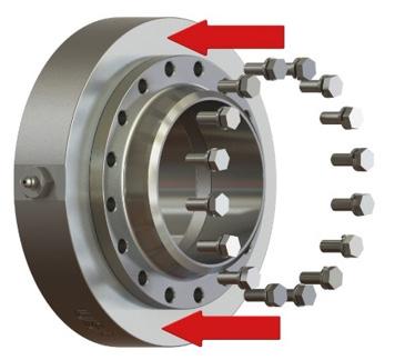
Reinstall the nose piece using the new bolts and washers in the replacement kit. Do not reuse old bolts and washers.
6
Torque the bolts to 25 ft-lbs. in a star pattern
Pressure testing is recommended prior to returning the swivel joint to service. If needed, this is a good time to clean and repaint any carbon steel parts to help protect them from the elements.
Once the seal replacement and pressure testing are complete the unit can be returned to service.
High Capacity Split Flange Swivel Joints
High Capacity Swivel Joints
Seal pack: pressure seal O-rings (2) and PTFE retainer
• For use in industries from petroleum, steel producing, blending plants, petrochemical, refining, mining, distilling, paint plants, farm irrigation and fertilizing, wastewater treatment, food and beverage process equipment, marine, and many more
• Ideal for high moment load applications on loading arms
Sizes
• 2", 3", and 4"
Features
• Bearing pack design allows easy seal change without removing the ball bearings
• Simple maintenance: remove one nose piece, replace seal pack, and reinstall with little downtime
• In-stream seal separates the wetted area from the ball bearings, allowing for longer bearing pack life compared to conventional swivels
• Dual wide-set bearing race and high strength bolts for higher moment loads
• Compact design for low-profile applications
• Full penetration weld
Materials
• Bearing pack: through hardened forged high-carbon alloy
• Material contact surfaces: stainless steel, carbon steel nose pieces
• Seals: Baylast™, FKM, PTFE, and more upon request
Specifications
• Pressure rating: up to 1,000 PSI
• Standard temperature range with Baylast™ seals is -30°F to 212°F (-34°C to 100°C); contact factory for other temperature requirements
Available options
• Swivel end configurations: 150 Ibs. and 300 Ibs. flanges, FNPT, MNPT, butt weld, TTMA, and others upon request
High Capacity Swivel Joints Numbering System
High Capacity Split Flange Style 20 - Weld x Weld
High Capacity Split Flange Style 20 - FNPT x FNPT
High Capacity Split Flange Style 20 - 150# Flange x 150# Flange
High Capacity Style 20 - 300# Flange x 300# Flange
High-Capacity Swivel Joint Seal Replacement Procedure
To change the seals in a Dixon® split flange swivel joint you will need the following items:
• 1/2” wrench or socket wrench with 1/2” socket
• Torque wrench
• Application-appropriate grease
• Repair kit
1
Follow your company guidelines to properly shut down the system and confirm there is no residual pressure in the line. Support or remove any components necessary to disconnect at least one nose piece.
2 Remove all the bolts and washers from one of the nose pieces. Pick the side that gives the best access to the seal gland.
3 Remove and discard the old O-rings and PTFE H-ring. Clean the seal gland area.
4
Lubricate the seal gland areas located on bottom of nose pieces touching the O-rings, the new H-ring seal grooves, and O-rings with grease.
5 Install the replacement O-rings and the new H-ring. Make sure the O-rings are set in each groove on the top and bottom of the H-ring. Be careful not to pinch the O-rings during reassembly.
6 Reinstall the nose piece using the new bolts and washers in the replacement kit. Do not reuse old bolts and washers.
7
Pressure testing is recommended prior to returning the swivel joint to service. If needed, this is a good time to clean and repaint any carbon steel parts to help protect them from corrosion.
Once the seal replacement and pressure testing are complete the unit can be returned to service.
Torque the bolts to 25 ft-lbs. in a star pattern
Dixon® Loading Arms
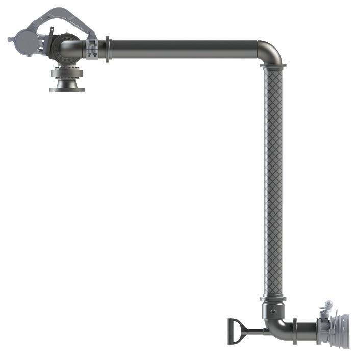
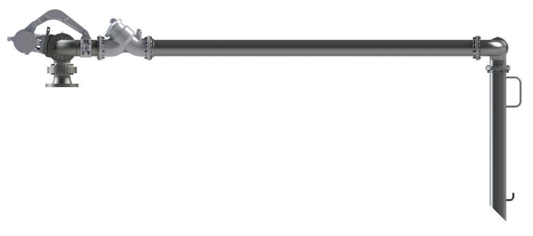
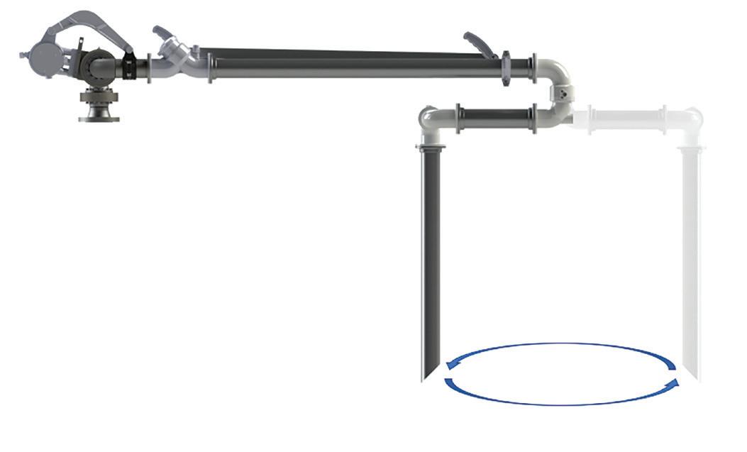
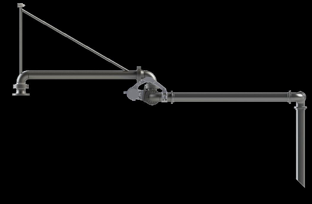
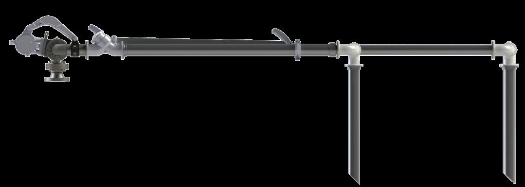
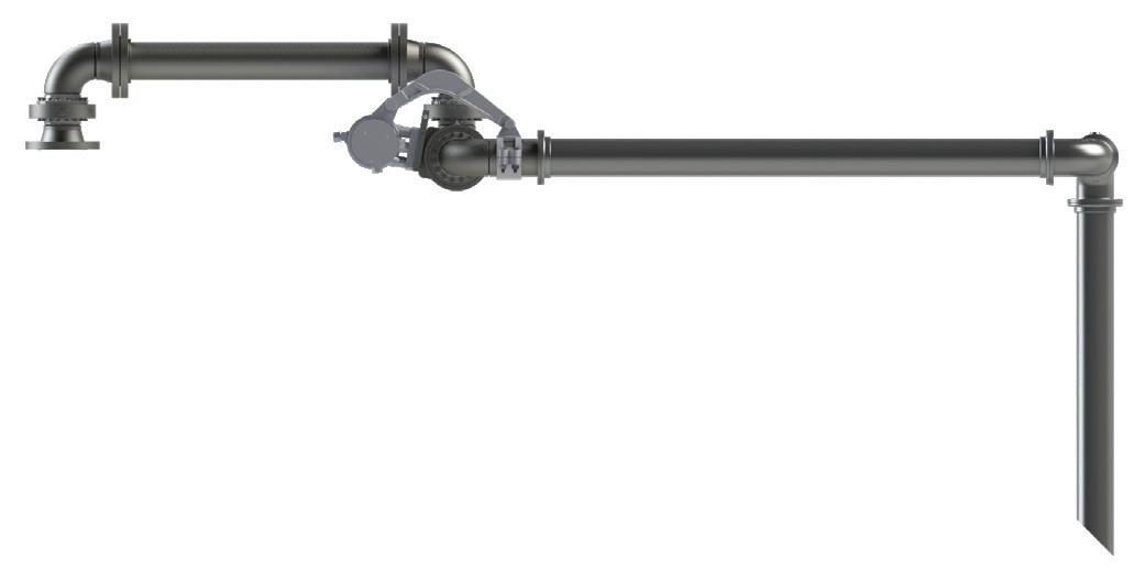
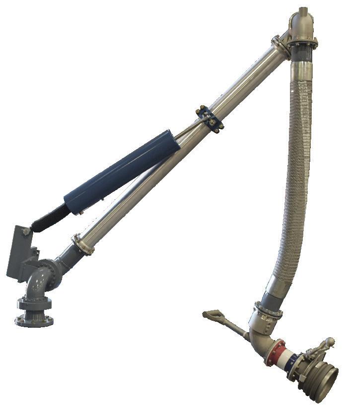
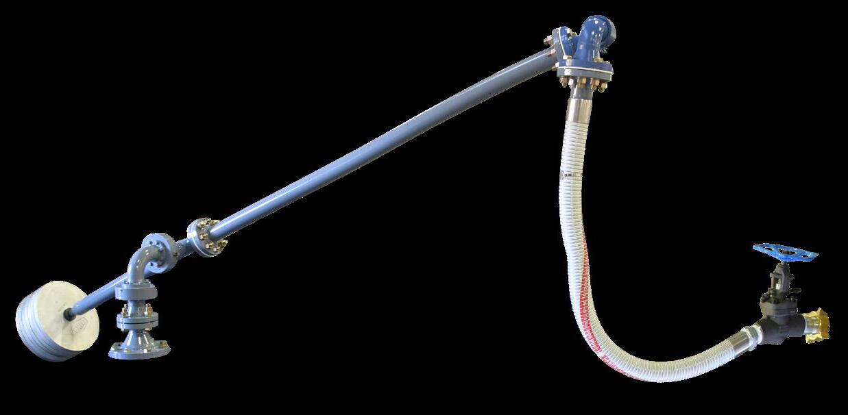
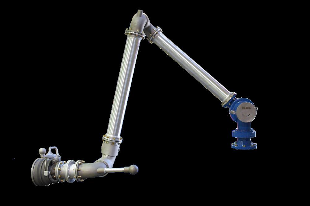
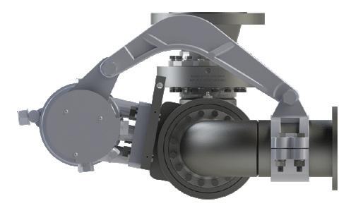
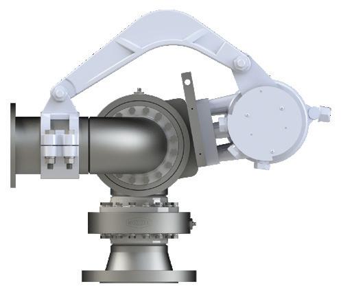
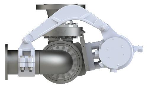
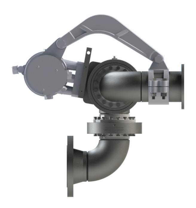
A loading arm is a dynamic system allowing for the transfer of media such as liquids, liquefied gas, or dry bulk from one storage vessel to another. Consisting of a combination of swivel joints, pipe and/or hose legs, a counterbalance, and various end connections, loading arms can be configured for both top loading and bottom loading applications. Dixon loading arms are ideal for a wide range of applications, transferring product to and from tank trucks or rail cars as well as to drums and totes.
Sizes
• 2", 3", 4", 6 ", and more upon request
Features
• Engineered with serviceability in mind
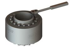
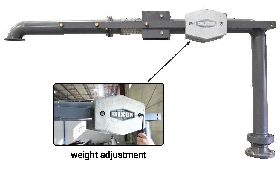
• Counterbalance options include compression springs, torsion springs, and counterweights
• Standard and customized options available
• Torsion spring counterbalance offered in left and right hand
• Multiple spring rates available for different load requirements
• Counterweight option available with 2 or 4 sliding weights
• Wide variety of end connections and accessories available
Materials
• Pipe leg materials offered: aluminum, carbon steel, and 316 stainless steel
• Available seals include: nitrile rubber, FKM, low-temperature FKM, PTFE, EPDM, and food-grade nitrile
• Drop hoses available in composite or stainless steel
NOTE: Visit dixonvalve.com/en/dixon-loading-arms for additional product information or call 888.226.4673.
Dixon Loading Arm Configurations
Counterweight Loading Arms counterweight base assembly
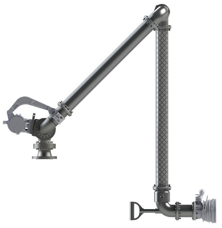
A-Frame Loading Arm with Drop Hose
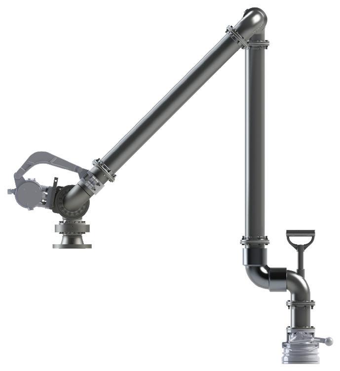
A-Frame Loading Arm with Rigid Drop Pipe
Horizontal Hose Loader
Dixon® Loading Arm Configurations
Fixed Reach Loading Arm
Scissor Style Loading Arm
Supported Boom Loading Arm
Telescoping Loading Arm expanded retracted
Unsupported Boom Loading Arm
Compression Spring Loading Arm
NOTE: Visit dixonvalve.com/en/dixon-loading-arms for additional product information or call 877.963.4966.
cantilever counterbalance
Cantilever Counterbalance Loading Arm
compact counterbalance
Compact Counterbalance Loading Arm
Base Swivels with Counterbalance
Materials
Sizes
• Carbon steel V-ring: 3”, 4”, and 6"
• Carbon steel split flange: 2", 3”, and 4”
• 316 stainless steel split flange: 2", 3”, and 4"
Features
• Torsion spring counterbalance offered in right or left hand
• Style 50 or 70 available for base swivels based on configuration and flow of media
• Connecting arm and clamp included
• Base swivel materials offered: carbon steel and 316 stainless steel
• Available seals include: nitrile rubber, FKM, low temperature FKM, PTFE, EPDM, or food-grade nitrile rubber
Specifications
• Standard configurations below include carbon steel split flange base swivel, ESB1 torsion spring counterbalance, 150# flange inlet, and TTMA flange outlet
• Three spring rates available: Light, medium, and heavy. Contact Dixon® to determine which is best for your application.
Orientation
Seals Counterbalance Spring 3" Part # 4" Part #
Nitrile rubber
UFRH
UFLH
Nitrile rubber
Light
Medium
Heavy
Light
Medium
Heavy
Light
Medium
Heavy
Light
Medium
Heavy
AB3G00000000000
BB3G00000000000
CB3G00000000000
AV3G00000000000
BV3G00000000000
CV3G00000000000
EB3G00000000000
FB3G00000000000
GB3G00000000000
EV3G00000000000
FV3G00000000000
GV3G00000000000
AB4G00000000000
BB4G00000000000
CB4G00000000000
AV4G00000000000
BV4G00000000000
CV4G00000000000
EB4G00000000000
FB4G00000000000
GB4G00000000000
EV4G00000000000
FV4G00000000000
GV4G00000000000
left hand style right hand style
Features
• TTMA-flanged aluminum loading arm swivel
Loading Arm Swivels
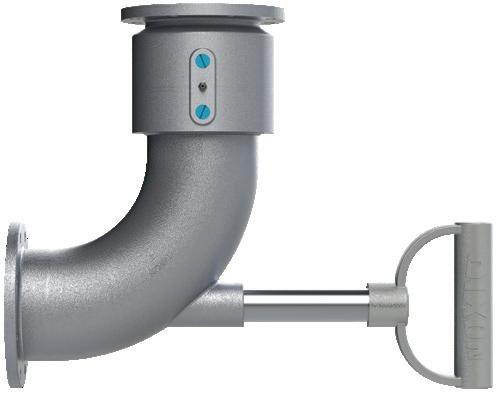
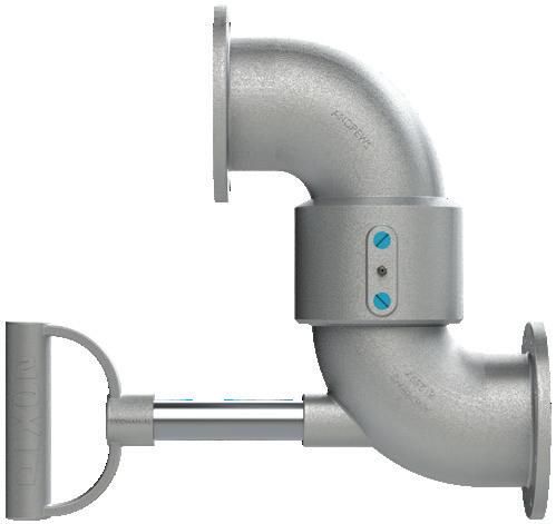
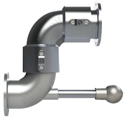
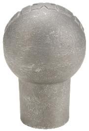
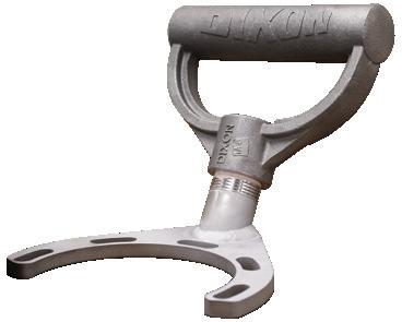
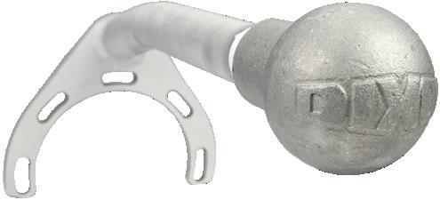
• Optional D-handle or ball handle is used to guide the connection of the API load coupler to the adapter on the tank truck
• Optional long radius elbow improves the flow into the API load coupler and provides spacing between the load arm and the tank truck
• Can be used with flange extensions and other TTMA flanged accessories
• Available seals include: nitrile rubber, FKM, low temperature FKM, EPDM, or food-grade nitrile
Description Handle Seal
style 20 no handle
D-handle
style 30 short radius
style 30 long radius
style 40
style 50
3" Part #
4" Part #
Nitrile rubber 320TFXTFAL00000 420TFXTFAL00000
FKM 320TFXTFAL11000 420TFXTFAL11000
Nitrile rubber 33HTFXTFAL00000 43HTFXTFAL00000
Nitrile rubber 33BTFXTFAL00000 43BTFXTFAL00000
FKM 33BTFXTFAL11000 43BTFXTFAL11000
FKM 33HTFXTFAL11000 43HTFXTFAL11000 ball handle
no handle
D-handle
ball handle
no handle
D-handle
ball handle
no handle
D-handle
ball handle
no handle
Nitrile rubber 330TFXTFAL00000 430TFXTFAL00000
FKM 330TFXTFAL11000 430TFXTFAL11000
Nitrile rubber 43HTFTFLAL00000
FKM 43HTFTFLAL11000
Nitrile rubber 43BTFTFLAL00000
FKM 43BTFTFLAL11000
Nitrile rubber 430TFTFLAL00000
FKM 430TFTFLAL11000
Nitrile rubber 34HTFXTFAL00000 44HTFXTFAL00000
FKM 34HTFXTFAL11000 44HTFXTFAL11000
Nitrile rubber 34BTFXTFAL00000 44BTFXTFAL00000
FKM 34BTFXTFAL11000 44BTFXTFAL11000
Nitrile rubber 340TFXTFAL00000 440TFXTFAL00000
FKM 340TFXTFAL11000 440TFXTFAL11000
Nitrile rubber 35HTFXTFAL00000 45HTFXTFAL00000
FKM 35HTFXTFAL11000 45HTFXTFAL11000
Nitrile rubber 35BTFXTFAL00000 45BTFXTFAL00000
FKM 35BTFXTFAL11000 45BTFXTFAL11000
Nitrile rubber 350TFXTFAL00000 450TFXTFAL00000
FKM 350TFXTFAL11000 450TFXTFAL11000
Loading Arm Swivel Replacement Parts
Description
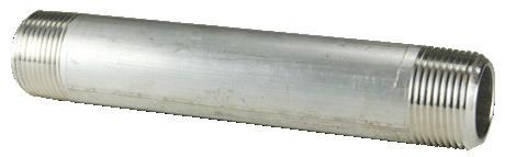
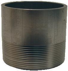
1" schedule 80 aluminum nipple
ball-style handle
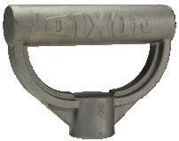
D-Style heavy-duty shovel handle
Part #
ATN100X7
100BHAN-AL
100DHAN-AL
style
style 30, short radius style
Application
400GTTFTK-1758Z
TTMA Weldable Flanges
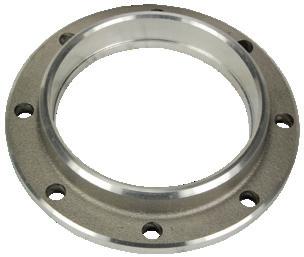
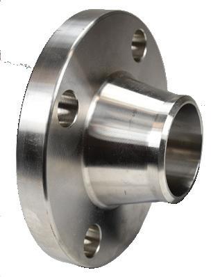
• Used in applications where a device such as a valve or sight flow indicator with a TTMA flange needs to be connected to a pipe; the TTMA weldable flange is welded to the pipe and the desired device is bolted on.
Features
• Flanges are 3/8" thick
• Easily connect with any item that has a 3" or 4" TTMA flange
Material
• Aluminum
Specification
• Flange connections are manufactured to connect with the Tank Truck Manufacturers Association (TTMA) flange pattern, see page 68 for flange dimensions.
Part #
TTF3AL 3" TTMA buttweld on flange
TTF4AL 4" TTMA buttweld on flange
TTF300SP 3" TTMA socket weld on flange
TTF400SP 4" TTMA socket weld on flange
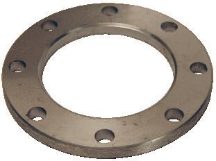
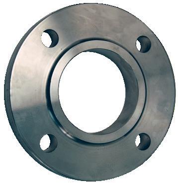
TTMA-32C 2" CS TTMA slip-on plate flange
TTMA-48C 3" CS TTMA slip-on plate flange
TTMA-64C 4" CS TTMA slip-on plate flange
Description
Product instruction sheets and technical data can be viewed at dixonvalve.com
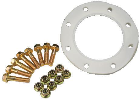
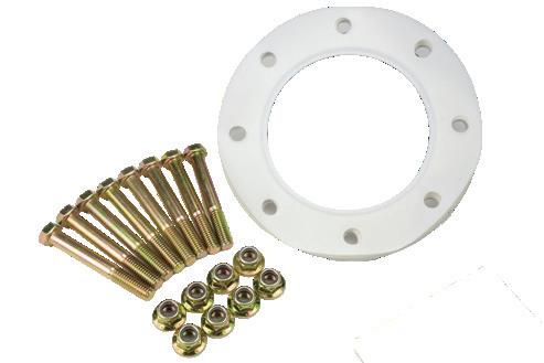
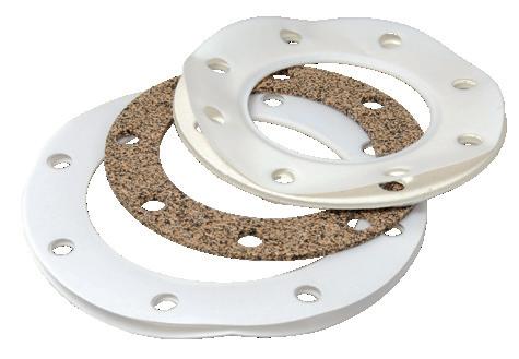
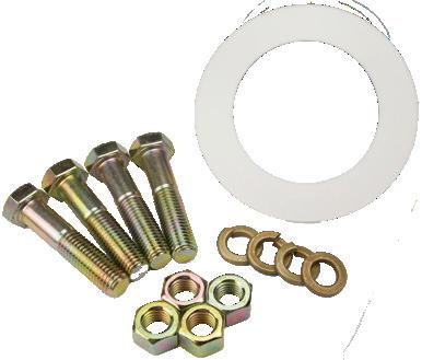
TTMA PTFE Envelope Klinger® Gasket Kit
Features
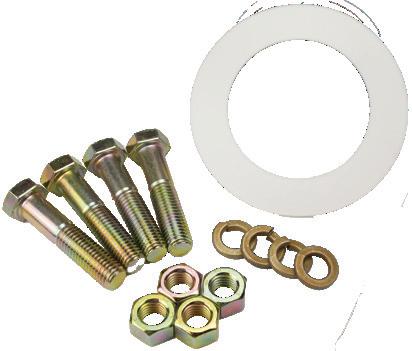
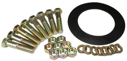
• TTMA PTFE envelope Klinger® gasket with 3/8" bolts and self-locking nuts
Sizes
• 3"-4"
Features
1-1/2"
1-3/4"
300GTTFTK-1508Z
300GTTFTK-1758Z 2"
300GTTFTK-2008Z 3"
300GTTFTK-3008Z 3-1/2"
1-1/2"
300GTTFTK-3508Z
400GTTFTK-1508Z 1-3/4"
400GTTFTK-1758Z 2"
400GTTFTK-2008Z 3"
400GTTFTK-3008Z 3-1/2"
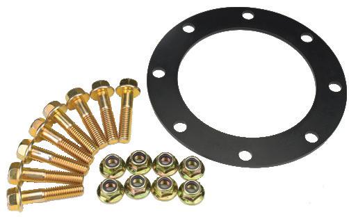
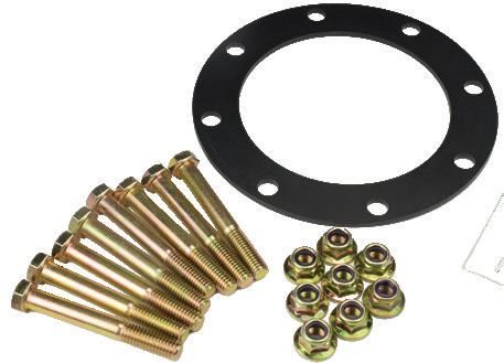
TTMA Baylast™ Gasket Kit
• TTMA Baylast gasket with 3/8" bolts and self-locking nuts
Nominal Pipe Size Outside Diameter Flange Flange Thickness Drill Template Number Holes Diameter Bolts Bolt Circle
Pressure Rating Chart
Spool or rotating assembly only - Pressure rating of final assembly may be derated due to end connections Swivel
* Contact Dixon for additional information
Dixon® swivels are recommended for use at the following maximum Non-Shock Cold Working Pressures (NSCWP) provided in PSI at ambient temperature 70°F (21°C) for 1" – 24" sizes:
• When using flanged ends, the pressure rating will be reduced to coincide with that of the flange being used. Carbon steel and stainless steel 150# flanges are recommended for use at 275 PSI maximum and 300# flanges at 740 PSI at ambient temperature 70°F (21°C).
• TTMA flanges are recommended for use at 150 PSI maximum at ambient temperature 70°F (21°C)
• Lubrication should be performed periodically, depending on service and operation conditions. Biannually is normally sufficient.
• All dimensions are approximate. Where critical, consult Dixon
Vacuum/Suction Applications:
Dixon O-Ring, V-Ring, and Split Flange swivel joints are rated for full vacuum service. However, distributors and end users are encouraged to consult with our factory providing detailed information about their specific application. Certain seal materials and end connections may not be compatible with vacuum service. For V-Ring swivel joints the seal orientation must be reversed for vacuum service. Standard hydrostatic testing will be performed on all swivel joints at the factory before shipping. Vacuum testing is available upon request.
Limited Warranty
DIXON VALVE AND COUPLING COMPANY, LLC (herein called "Dixon") warrants the products described herein and manufactured by Dixon to be free from defects in material and workmanship for a period of one (1) year from date of shipment by Dixon under normal use and service. Its sole obligation under this warranty being limited to repairing or replacing, as hereinafter provided, at its option any product found to Dixon's satisfaction to be defective upon examination by it, provided that such product shall be returned for inspection to Dixon's factory within three (3) months after discovery of the defect. The repair or replacement of defective products will be made without charge for parts or labor. This warranty shall not apply to: (a) parts or products not manufactured by Dixon, the warranty of such items being limited to the actual warranty extended to Dixon by its supplier; (b) any product that has been subject to abuse, negligence, accident, or misapplication; (c) any product altered or repaired by others than Dixon; and (d) to normal maintenance services and the replacement of service items (such as washers, gaskets, and lubricants) made in connection with such services. To the extent permitted by law, this limited warranty shall extend only to the buyer and any other person reasonably expected to use or consume the goods who is injured in person by any breach of the warranty. No action may be brought against Dixon for an alleged breach of warranty unless such action is instituted within one (1) year from the date the cause of action accrues. This limited warranty shall be construed and enforced to the fullest extent allowable by applicable law.
Other than the obligation of Dixon set forth herein, Dixon disclaims all warranties, express or implied, including but not limited to any implied warranties of merchantability or fitness for a particular purpose, and any other obligation or liability. The foregoing constitutes Dixon's sole obligation with respect to damages, whether direct, incidental, or consequential, resulting from the use or performance of the product.
Some products and sizes may be discontinued when stock is depleted or may require a minimum quantity for ordering.
About This Brochure and Our Products
This brochure is intended as a product offering. It is not a user or technical manual. Information in this brochure is subject to change without notice. We may modify product design and specification without notice and without any obligation to modify or substitute products previously purchased. All users and distributors of products sold through this brochure are strongly encouraged to contact Dixon with questions on use, compatibilities, coupling procedures, and life of product. Our full-time engineering and test staff are always available to recommend uses and to assist distributors and users with questions.
Safety
Safety logos, which appear throughout our brochure, are used as a reminder that the user should carefully review for the appropriateness of the product for the media, application, and environment in which it will be used.
NOTE: Because of the health hazards associated with contamination and lead content in drinking water systems, Dixon couplings, unless otherwise specifically approved, are not recommended for potable water service and should not be used in applications where drinking water will contact the wetted surfaces of the coupling.
All Dixon products are shipped in cartons with the following warning: "WARNING: This product contains lead, a chemical known to the State of California to cause cancer and birth defects or other reproductive harm."
Trademarks
Delrin® and Zytel® are registered trademarks of DuPont Nemours and Company.
Kalrez® is a registered trademark of DuPont Dow Elastomers.
All other trademarks appearing in the Dixon illustrated price list are the property of their respective owners.
All rights reserved. This book is copyrighted material. Use, reproduction or copying of it by anyone other than Dixon® is strictly forbidden without its express written consent.
NOTE: Reasonable care has been taken in preparing this brochure. Dixon Valve & Coupling Company, LLC reserves the right to make corrections.