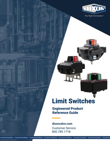
Limit Switches Engineered Product Reference Guide dixonvalve.com Customer Service 800.789.1718 1
800.789.1718 • dixonvalve.com
DSEPRG2023_HSG
Limit Switches
Table of Contents XLS-B4-Series Limit Switch........................................................................................................................................................................3 Dimensions..............................................................................................................................................................................................4 XLS-C4-Series Limit Switch........................................................................................................................................................................5 Dimensions..............................................................................................................................................................................................6 XLS-C7-Series Limit Switch........................................................................................................................................................................7 Dimensions..............................................................................................................................................................................................8 XLS-C-Series Part Number Key..................................................................................................................................................................9 Limited Warranty.......................................................................................................................................................................................11
2
800.789.1718 • dixonvalve.com
DSEPRGLimitSwitch_0926
XLS-B4-Series
XLS-B4-Series Limit Switch The XLS-B4 series limit switch has been designed to provide rotary pneumatic actuators with a local and remote indication of valve position in a variety of applications. This limit switch is manufactured from die-cast aluminum and powder epoxy-coated with stainless steel fasteners and shaft. With a weather-proof NEMA 4/4X and IP68 rating, the XLS-B4 is corrosion resistant and suitable for most environments. Features • UL approved • Compact, cost-efficient limit switches for both local and remote indication of valve and or actuator position • Visual position indicator • Quick-set adjustable cams • Multipoint terminal strip • Dual wire potting • Captive cover bolts • NEMA 4/4X • Standard NAMUR mounting Materials • Indicator: polycarbonate • Housing: black polyester powder-coated die cast aluminum • Bracket: 304 stainless steel Specifications • Weight: 1.9 lbs • Enclosure: weatherproof, IP68 • Temperature range: -4°F to 185°F (20°C to 85°C) • Cable entry: (2) 1/2" NPT • Position indicator: 0° to 90° indication with open (yellow) and closed (red), L and T flow indication • Switch types: mechanical (2) SPDT • Maximum voltage: 250VAC/VDC • Current data - 0.6A 125VDC - 0.3A 250VDC - 16A 125/250VAC
XLS-B4-Series Part Number Table Part #
Description
XLS-B4A0120P
IP68 enclosure, open/closed indicator, mechanical SPDT, (2) switches, 8 point terminal strip, (2) 1/2" NPT cable entry
XLS-B4L0120P
IP68 enclosure, L-port indicator with clear cover, mechanical SPDT, (2) switches, 8 point terminal strip, (2) 1/2" NPT cable entry
XLS-B4T0120P
IP68 enclosure, T-port indicator with clear cover, mechanical SPDT, (2) switches, 8 point terminal strip, (2) 1/2" NPT cable entry
XLS-B4AJ
replacement 2-way cover assembly
XLS-B4-IC
replacement clear cover
DSEPRGLimitSwitch_0926
800.789.1718 • dixonvalve.com
3
XLS-B4-Series
XLS-B4-Series Limit Switch – Dimensions 4.8" 3.0"
5.3" 3.6"
1.1" 0.3" 0.1" 4.1" 3.3" 3.0" 0.4" 0.16"
0.2" 1.2"
4
800.789.1718 • dixonvalve.com
DSEPRGLimitSwitch_0926
XLS-C4-Series XLS-C4-Series Limit Switch The XLS-C4-series limit switch provides a compact design and cost effective solution for both visual and remote electrical indication of rotary valve/actuator position. This series is the ideal switch for applications requiring proximity switches or AS-interface. Hermetically sealed and solid state switch options also make the XLS-C4 series suitable for use in intrinsically safe applications and Class I Division 2 Groups A, B, C, D, and Class II Division F and G hazardous applications. Features • The polyester coating inside and outside as well as the stainless steel shaft make this unit ideal for use in harsh environments • Multiple switch options include mechanical, proximity, and inductive switches • Visual position indication: 3D beacon provides high visibility confirmation of valve actuator position • "Easy-set" cams are splined, spring-loaded, and independently adjustable. This design offers tool-free calibration and positive vibration resistant engagement • Standard with two 1/2" NPT cable entries Materials • Cover: polycarbonate, aluminum, or stainless steel • Housing: aluminum, polyester-coated, or stainless steel • Shaft: stainless steel • Cam/splines: UV resistant polycarbonate • 3D beacon: UV resistant polycarbonate • Terminal block: stainless steel screws and PVC housing Specifications • Weight: 1.25 lbs • Temperature range: -4°F to 176°F (20°C to 80°C) • Approvals: UL, NEMA 4/4X Class I Division 2 Groups A, B, C, D, and Class II Division 2 Groups F and G NOTE: See page 8 for part number key.
XLS-C4-Series Limit Switch – Dimensions 1.58"
4.72"
/2"
1 (2)
T
NP
3.73" 1.32" 0.97" 0.16"
0.16"
0.32"
0.47" 1.14"
50.00 mm
3.16"
M6x1 - 6H
DSEPRGLimitSwitch_0926
800.789.1718 • dixonvalve.com
5
XLS-C7-Series XLS-C7-Series Limit Switch The XLS-C7 series hazardous location explosion-proof limit switch provides an effective solution for both visual and remote electrical indication of the valve/actuator position. The heavy-duty design and wide variety of options make the XLS-C7 series the ideal limit switch for use in NEMA 7 and 9 applications. Features • Limit switch for both local and remote indication of valve/actuator position • Wide variety of switch options are available • Visual position indicator • Quick-set adjustable cams • Multipoint terminal strip • Dual wire potting • Captive cover bolts • UL approved - Class I Division 1 Groups C, D and Division 2 Groups A, B, C, and D - Class II Division 1 Groups E, F, G and Division 2 Groups F and G • NEMA 4, 4X, 7, and 9 • Standard NAMUR mounting Materials • 3D beacon: UV resistant and 94-V0 polycarbonate • Painting: black polyester powder coating • Cover: die chromated aluminum • Body: die chromated aluminum • Shaft: stainless steel • Fasteners: stainless steel Specifications • Weight: 4 lbs • Cable entry: (2) 1/2" NPT • Position indicator • Option for NAMUR proximity switches for intrinsically safe applications • AS-I digital communication interface card option • Temperature range: -4°F to 176°F (-20°C to 80°C) • Switch approvals - Class I Division 1 Groups C and D - Class I Division 2 Groups A, B, C, D (proximity sensors only) - Class II Division 1 Groups E, F, G - Class II Division 2 Groups F and G NOTE: See page 8 for part number key.
6
800.789.1718 • dixonvalve.com
DSEPRGLimitSwitch_0926
XLS-C7-Series
XLS-C7-Series Limit Switch – Dimensions 6.7" 3.3"
5.4"
1.3" 0.3" 0.2"
5.5"
0.2"
0.5"
XLS-C-Series Limit Switch Bracket – Dimensions
1.80"
3.95"
2.00"
1.38"
1.97" 4x
4x
0.28"
2x 1.19"
0.22"
4x 0.21" 3.10"
NOTE: Bracket shown withNote: XLS-C-series limit switch. PartSeries number LSPP-BK-S-N Bracket shown used with XLS-C limit is swtich. Part Number: LSPP-BK-S-N DSEPRGLimitSwitch_0926
800.789.1718 • dixonvalve.com
7
XLS-C-Series XLS-C-Series Limit Switch – Part Number Key XLS-C-Series Limit Switch Part Number Key Example: XLS-C7A0120P
Series Enclosure Indicator XLS-C
7
A
Switch Type 01
Switch Terminal Quantity Strip 2
0
Cable Entry P
Series Code XLS-C XLS-C Enclosure Code IP66/67 aluminum body with 1 polycarbonate cover IP66/67 aluminum body ATEX and IECEx 3 intrinsically safe NEMA 4/4X aluminum body with 4 polycarbonate cover (standard) NEMA 4/4X with 316 stainless steel enclosure 5 NEMA 4/4X with aluminum enclosure 6 Nema 4/4X, 7 & 9 with aluminum enclosure 7 (explosion proof) Indicator Code Open/closed A L-port L T-port T none N Switch Type Code SPDT el. mech. switch silver-plated contacts 01 SPDT el. mech. switch gold-plated contacts 02 (required for ATEX and IECEx enclosure) SPDT magnetic reed hermetically sealed 10 proximity switches 4-20mA position transmitter TR AS-Interface AS Inductive sensors, 2 wires NO, 5-60 VDC 32 operating voltage, 2-100mA operating current Inductive NAMUR sensors, 2 wires, up to SIL3, 70 Exia ready Switch Quantity Code 2 2 3 3 1 4 4 Terminal Strip Code Screw terminals with solenoid 0 connection (standard) AS-I terminal 1 Blue screw type terminals with solenoid connection (required ATEX and 3 IECEx enclosure) Cable Entry Code 2 x 2-1/2" NPT (standard) P 2 x M20-1.5 M 2 x 1/2" NPT + 1 x 3/4" NPT1 N Available for enclosure code 7
1
8
800.789.1718 • dixonvalve.com
DSEPRGLimitSwitch_0926
XLS-C-Series Notes
DSEPRGLimitSwitch_0926
800.789.1718 • dixonvalve.com
9
XLS-C-Series
Notes
10
800.789.1718 • dixonvalve.com
DSEPRGLimitSwitch_0926
XLS-C-Series
Limited Warranty DIXON VALVE & COUPLING COMPANY, LLC (herein called "Dixon") warrants the products described herein and manufactured by Dixon to be free from defects in material and workmanship for a period of one (1) year from date of shipment by Dixon under normal use and service. Its sole obligation under this warranty being limited to repairing or replacing, as hereinafter provided, at its option any product found to Dixon's satisfaction to be defective upon examination by it, provided that such product shall be returned for inspection to Dixon's factory within three (3) months after discovery of the defect. The repair or replacement of defective products will be made without charge for parts or labor. This warranty shall not apply to: (a) parts or products not manufactured by Dixon, the warranty of such items being limited to the actual warranty extended to Dixon by its supplier; (b) any product that has been subject to abuse, negligence, accident, or misapplication; (c) any product altered or repaired by others than Dixon; and (d) normal maintenance services and the replacement of service items (such as washers, gaskets, and lubricants) made in connection with such services. To the extent permitted by law, this limited warranty shall extend only to the buyer and any other person reasonably expected to use or consume the goods who is injured in person by any breach of the warranty. No action may be brought against Dixon for an alleged breach of warranty unless such action is instituted within one (1) year from the date the cause of action accrues. This limited warranty shall be construed and enforced to the fullest extent allowable by applicable law. Other than the obligation of Dixon set forth herein, Dixon disclaims all warranties, express or implied, including but not limited to any implied warranties of merchantability or fitness for a particular purpose, and any other obligation or liability. The foregoing constitutes Dixon's sole obligation with respect to damages, whether direct, incidental, or consequential, resulting from the use or performance of the product. Some products and sizes may be discontinued when stock is depleted or may require a minimum quantity for ordering.
Limits of Liability This brochure is intended as a product offering. It is not intended to be a user or technical manual. Information in this brochure is subject to change without notice. All users and distributors of products sold through this brochure should contact Dixon with questions of use, compatibilities, coupling procedures, and life of product. Our full-time engineering and test staff are always available to recommend uses and to assist distributors and users with any questions.
Safety Safety logos, which appear throughout our catalog, are used as a reminder that the user should carefully review for the appropriateness of the product for the media, application, and environment in which it will be used. NOTE: Because of the health hazards associated with contamination and lead content in drinking water systems, Dixon couplings, unless otherwise specifically approved, are not recommended for potable water service and should not be used in applications where drinking water will contact the wetted surfaces of the coupling. All Dixon products are shipped in cartons with the following warning: "WARNING: This product contains lead, a chemical known to the State of California to cause cancer and birth defects or other reproductive harm."
Trademark
Delrin® and Zytel® are registered trademarks of E. I. du Pont de Nemours and Company. Kalrez® is a registered trademark of DuPont Dow Elastomers. All other trademarks appearing in the Dixon illustrated product list are the property of their respective owners.
Copyright Copyright © 2026 by Dixon Valve & Coupling Company, LLC All rights reserved. This book is copyrighted material. Use, reproduction or copying of it by anyone other than Dixon® is strictly forbidden without its express written consent. NOTE: Reasonable care has been taken in preparing this catalog. Dixon Valve & Coupling Company, LLC reserves the right to make corrections.
DSEPRGLimitSwitch_0926
800.789.1718 • dixonvalve.com
11
Dixon
Phone: 877.963.4966 Email: sales@dixonvalve.com dixonvalve.com
connect with us on
© 2026 DVCC
12
Printed in the USA
DSEPRGLimitSwitch_0926_Rev3
800.789.1718 • dixonvalve.com
DSEPRG2023_HSG